manuals.online logo
Brands
  1. Home
  2. •
  3. Brands
  4. •
  5. GAGEMAKER
  6. •
  7. Measuring Instrument
  8. •
  9. GAGEMAKER PD-8000-RSC User manual

GAGEMAKER PD-8000-RSC User manual

Thread Inspection
®
PD-8000-RSC
Rotary Shouldered
Pin Connection
PD-8000-RSC
Rotary Shouldered
Pin Connection
OPERATION MANUAL
Mark Here
Procedures for Using the Pin Pitch Diameter Location Template and the
PD-8000-RSC External Pitch Diameter Gage
1. With the prole’s reference mark facing you and
the connector shoulder to your left, place the LPP
template on the threaded connector so the teeth
seat fully into the threads. The last length of the
template does not contact the shoulder.
2. With the teeth of the template seated fully in
the threads of the connector, slide the template
clockwise or away from you around the connector
until the left end of the template makes contact with
the pin shoulder. This is a rough clocking position.
3. Using a Sharpie® felt marker, place a mark on the
pin shoulder next to where the template contacts
the shoulder. Jog or rotate the machine spindle
until this mark is at the 12:00 o’clock position. This
makes it easier to locate and mark the measurement
position.
4. Place the template back onto the pin threads
just before the mark on the shoulder. Be sure that
the template threads are fully seated and parallel to
the pin centerline. Using a slight twisting motion,
slide the template in a clockwise direction or away
from you until the left edge of the template contacts
the shoulder. The twisting motion ensures that
the template is seated properly in the threads and
against the pin shoulder.
The pin pitch diameter location template or LPP is similar to a standard thread prole template with a
locator reference mark and a special shaped reference tooth. These reference indicators are used to
position and mark the location at which the pitch diameter of the connector will be measured. The LPP
location template works on standard pins as well as pins connectors with relief grooves. There are 11
different LPP templates based on specic TPI, TPF, and Thread forms.
The PD-8000-RSC gage measures the deviation from nominal pitch diameter for the connector being
inspected. The gage uses xed and a moveable contact balls that are set into the thread’s helical path
at a predetermined location. The deviation is read directly from the indicator.
Applying the LPP to the Pin Connector
Mark now at 12 o’clock
© 2014 Gagemaker, LP

Measuring the Pitch Diameter of the Pin Connector
5. Using a Sharpie® felt marker, mark the crests
of the two threads on either side of the locator
reference marks. This is the location where the
xed contact ball of the PD-8000-RSC gage will be
placed when measuring the pitch diameter.
6. Repeat steps 4 and 5 to verify proper template
location. Holding the template rmly into the
threads will ensure the left edge is parallel and
square against the pin shoulder.
7. The connection is now properly marked and
ready to measure the pitch diameter using the
PD-8000-RSC gage.
1. The PD-8000-RSC gage must be preset and
locked to a calculated dimension for the particular
connector you are inspecting. It is recommended
that a ground setting standard rod or a MIC TRAC
is used for presetting the gage. Gages, setting
standards, and parts should be at the same
temparture.
2. To preset the gage, loosen the lower arm lock
screw and slide it to the approximate location where
the standard will t between the contact points.
Applying the LPP to the Pin Connector (Cont.)
Measuring the Pitch Diameter of the Pin Connector
3. With the lower arm loose, slide the arm toward
the indicator approximately .100” and tighten the
lock screw using a 1/8” Allen wrench. This will
preload the indicator .100” as the gage is zeroed.
4. Place the standard between the contact points,
sweep the standard in a small circular motion to
locate the smallest reading and zero the indicator.
The reading on the indicator is the amount of deviation from the nominal pitch diameter.
5. With the indicator on the bottom side of the
connector, place the xed contact ball at the point
where the LPP was located and marked.
6. Trace the same thread groove counter-clockwise
to the opposite side of the connector and place the
moveable contact ball in that thread groove.
7. While holding the xed contact ball at the marked
location, sweep the gage to locate the largest
indicator reading.
OFF
OFF
ON
OFF
ON
SET
SET
MODE
MODE
SET
SET
SET
SET
MODE
MODE
SET
SET
SET
SET
SET
SET
SET
SET
SET
SET
SET
SET
MODE
MODE
MODE
MODE
MODE
MODE
MODE
MODE
MODE
SET
SET
Measurement mode
P
Reverse direction
Setting tolerance
judgment function
Changing resolution
Setting calculation function
Setting function lock
Press(within 2 sec.)
Press and hold
(2sec. or more)
inch :0.00005
0.0001,0.0005
mm :0.001,0.01
OFF
ON
OFF
ON
Setting preset value
(ABS mode)
ABS mode ⇔INC mode
(Preset )(Zero-setting)
SET
・Power On
・Holding displayed value or
External output of displayed value
Power Off
DATA ON・OFF
Function lock. The content of the
operation has been limited.
Reverse counting
Calculation function display.
Displayed value= Calculation coefficient
×Spindle displacement
◇Meaning of the icons
※
※0.001mm,.00005”model only
To calculation
Coefficient
setting
Selection
sign
next digit
Repeat the above
procedures until
all digits
Complete setting
Selection
Selection
Selection
Selection
Selection
◇Key pressing method
ON
(Normal)
ON
(Enlarged)
No
change
Setting tolerance Setting preset value
(Refer to the
user’s manual)
Quit setting mode
Upper limit value setting
Changing
Tolerance
limit value
The setting method is the same as the
Upper limit value setting.
Lower limit
value setting
Zero-setting
(INC mode)
・To cancel the setting halfway, press and hold
the MODE key in area . It returns to the state
in front of one. It can return to measurement mode
by repeating the same operation.
・Clears all settings when the battery is put in again.
Forward direction
Switching counting
direction
No
change
Changing
preset value
Selection
value
next digit
in ⇔mm
(in/mm model only)
Parameter Setting Mode
HOW TO CHANGE RESOLUTION
1) PRESS AND HOLD MODE BUTTON FOR MORE THAN
TWO SECONDS
MODE
2) PRESS(DON’T HOLD) MODE BUTTON TWICE
MODE
A BLINKING res. WILL BE DISPLAYED
3) PRESS THE SET BUTTON (THE res. ON DISPLAY WILL STOP BLINKING)
SET
4) PRESS MODE BUTTON TO TOGGLE BETWEEN RESOLUTION
[(.00005”, .0001”, 0.005” OR 0.001”, 0.01”)]
MODE
5) PRESS THE SET BUTTON
SET
MODE 6) PRESS AND HOLD MODE BUTTON FOR MORE THAN TWO SECONDS
TO RETURN TO STANDARD MEASUREMENT MODE
Press(within 2 sec.)
Press and hold
(2sec. or more)
HOW TO CHANGE LINEAR DIRECTION
MODE 1) PRESS AND HOLD MODE BUTTON FOR MORE THAN
TWO SECONDS
A BLINKING Dir. WILL DISPLAY
2) PRESS THE SET BUTTON (THE Dir. ON DISPLAY WILL STOP BLINKING)
3) PRESS MODE BUTTON TO TOGGLE BETWEEN (BLANK) AND (REVERSE DIRECTION)
SET
MODE
4) PRESS(DON’T HOLD) THE SET BUTTON
MODE
SET
5) PRESS AND HOLD MODE BUTTON FOR MORE THAN TWO SECONDS
TO RETURN TO STANDARD MEASUREMENT MODE
Press(within 2 sec.)
Press and hold
(2sec. or more)
Notes:
© 2016 Gagemaker, LP
JSS and Gagemaker are registered trademarks of Gage-
maker, LP.
All rights reserved
Gagemaker LP, P.O. Box 87709, Houston, Texas 77287-7709
712 East Southmore Ave., Pasadena, Texas 77502
Phone: 713-472-7360
Fax: 713-472-7241
Web site: www.gagemaker.com
© 2016 Gagemaker, LP

Other GAGEMAKER Measuring Instrument manuals

GAGEMAKER PG-6000 User manual

GAGEMAKER

GAGEMAKER PG-6000 User manual

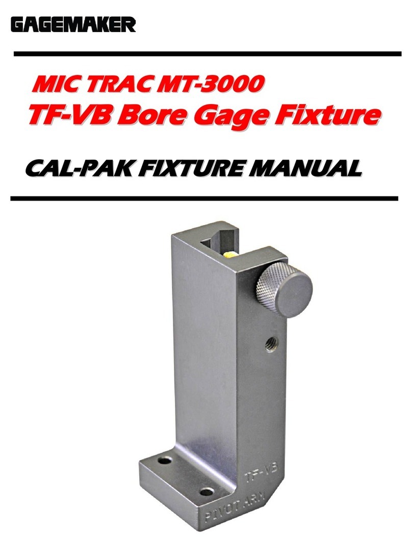
GAGEMAKER MIC TRAC MT-3000 User manual

GAGEMAKER

GAGEMAKER MIC TRAC MT-3000 User manual

GAGEMAKER MRP-1500 User manual

GAGEMAKER

GAGEMAKER MRP-1500 User manual

GAGEMAKER MIC TRAC MT-3000 User manual

GAGEMAKER

GAGEMAKER MIC TRAC MT-3000 User manual

GAGEMAKER BXG-1000 User manual

GAGEMAKER

GAGEMAKER BXG-1000 User manual

GAGEMAKER RG-7000 User manual

GAGEMAKER

GAGEMAKER RG-7000 User manual

GAGEMAKER LG-5003 User manual

GAGEMAKER

GAGEMAKER LG-5003 User manual

GAGEMAKER PD-6001 User manual

GAGEMAKER

GAGEMAKER PD-6001 User manual

GAGEMAKER MIC TRAC MT-3000 User manual

GAGEMAKER

GAGEMAKER MIC TRAC MT-3000 User manual

GAGEMAKER LG-6001 User manual

GAGEMAKER

GAGEMAKER LG-6001 User manual

GAGEMAKER MIC TRAC MT-3000 User manual

GAGEMAKER

GAGEMAKER MIC TRAC MT-3000 User manual

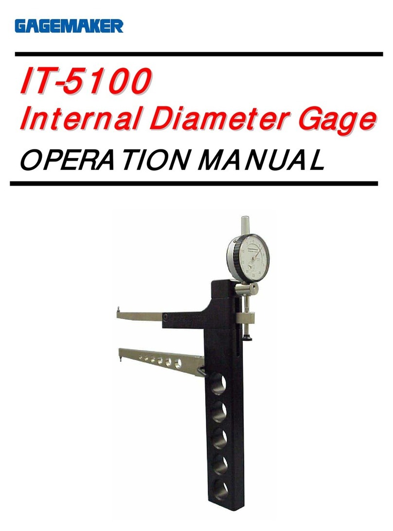
GAGEMAKER IT-5100 User manual

GAGEMAKER

GAGEMAKER IT-5100 User manual

GAGEMAKER CA-9001 User manual

GAGEMAKER

GAGEMAKER CA-9001 User manual

Popular Measuring Instrument manuals by other brands

FLIR EXTECH HDV-WTX1 Product sheet

FLIR

FLIR EXTECH HDV-WTX1 Product sheet

Endress+Hauser Proline Promag P 100 technical information

Endress+Hauser

Endress+Hauser Proline Promag P 100 technical information

Photonic UV254 GO! instruction manual

Photonic

Photonic UV254 GO! instruction manual

DeFelsko PosiTector SHD Standard manual

DeFelsko

DeFelsko PosiTector SHD Standard manual

R&S ZNH user manual

R&S

R&S ZNH user manual

YOKOGAWA AQ2160-01 user manual

YOKOGAWA

YOKOGAWA AQ2160-01 user manual

GENERAL RADIO COMPANY 620-A Maintenance instruction book

GENERAL RADIO COMPANY

GENERAL RADIO COMPANY 620-A Maintenance instruction book

Badger Meter ER-500 Programming manual

Badger Meter

Badger Meter ER-500 Programming manual

NDC BenchMike Pro Instruction handbook

NDC

NDC BenchMike Pro Instruction handbook

Leupold RX-600 Series Operation manual

Leupold

Leupold RX-600 Series Operation manual

multicomp pro MP780892 user manual

multicomp pro

multicomp pro MP780892 user manual

Tektronix P6202A instruction manual

Tektronix

Tektronix P6202A instruction manual

Vigor V2795 operating instructions

Vigor

Vigor V2795 operating instructions

DAKOTA ULTRASONICS DX-1 manual

DAKOTA ULTRASONICS

DAKOTA ULTRASONICS DX-1 manual

GASTRON GIR-3000 instruction manual

GASTRON

GASTRON GIR-3000 instruction manual

Omega FL-7600 Series Install manual

Omega

Omega FL-7600 Series Install manual

Leica DISTO S910 Frequently asked questions

Leica

Leica DISTO S910 Frequently asked questions

Siemens MPA 1 Series instruction manual

Siemens

Siemens MPA 1 Series instruction manual

manuals.online logo
manuals.online logoBrands
  • About & Mission
  • Contact us
  • Privacy Policy
  • Terms and Conditions

Copyright 2025 Manuals.Online. All Rights Reserved.