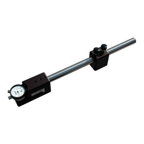
GAGEMAKER MRP-1500 User manual

MRP Pitch Diameter Gage
Models 1500/2500/3500
OPERATION MANUAL

Pitch Diameter Gage Operation Manual Models MRP 1500/2500/3500
Copyright © 2018 Gagemaker. All rights reserved
2
©2018 Gagemaker, LP
MRP and Gagemaker are registered trademarks of Gagemaker, LP.
All rights reserved
OMMRP15005-18

Pitch Diameter Gage Operation Manual Models MRP 1500/2500/3500
Copyright © 2018 Gagemaker. All rights reserved
3
Contents
Introduction
Technical Support 5
Product Information and Updates 5
Parts List 6
MRP Gage Setup 7
Setup Procedures for External Measurements
MRP Dimensional Limits Chart 8
Setting Up the MRP Gage for External Measurements 9
Zeroing the MRP Gage for External Measurements Using Rod Standards 13
Zeroing the MRP Gage for External Measurements Using Frame Standards 17
Zeroing the MRP Gage for External Measurements Using the MIC TRAC 21
Operating Procedures for External Measurements
Inspecting External Parts 28
Setup Procedures for Internal Measurements
MRP Dimensional Limits Chart 31
Setting Up the MRP Gage for Internal Measurements 32
Zeroing the MRP Gage for Internal Measurements Using Rod Standards 36
Zeroing the MRP Gage for Internal Measurements Using Frame Standards 40
Zeroing the MRP Gage for Internal Measurements Using the MIC TRAC 44
Operating Procedures for Internal Measurements
Inspecting Internal Parts 51
Inspection Criteria
Determining Diameter and Ovality Measurements with the MRP Gage 54
MRP Inspection Tolerance Guidelines 55
MRP Accuracy Measurement Factors
Thread Addendum Measurements 56
Standoff vs. Pitch Diameter Change 57
Setting Standard Calculations
Rod Style Setting Standard Dimensions 58
Rod Style Setting Standard Correction Factors 60
MIC TRAC Setting Standard Dimensions 61

Pitch Diameter Gage Operation Manual Models MRP 1500/2500/3500
Copyright © 2018 Gagemaker. All rights reserved
4
MIC TRAC Setting Dimensions for the MRP Gage
API Line Pipe Connections - 1” to 20” 62
API NUE Connections - ¾” to 4½” 62
API EUE Connections - ¾” to 4½” 63
API STC Connections - 4½” to 20” 63
API LTC Connections - 4½” to 20” 64
API Buttress Connections - 4½” to 13⅜” 64
API Buttress Connections – 16” to 20” 64
Care and Maintenance
Maintenance Tips 65
Warranty Information 65

Pitch Diameter Gage Operation Manual Models MRP 1500/2500/3500
Copyright © 2018 Gagemaker. All rights reserved 5
Congratulations! Your decision to purchase a Gagemaker product above all others on the market
demonstrates your confidence in our quality and workmanship.
To insure the high performance and operation of our product, we urge you to use the included reference
materials. They contain important information for proper setup and use of the equipment. Also, we
recommend that you follow the care and maintenance tips in this manual to keep the equipment working
in top condition.
If your questions have not been addressed in our reference materials, contact your local
representative or a customer service representative at 713-472-7360.
Introduction
The MRP Gages inspect the pitch diameter and ovality of internal and external tapered threads ranging
from 1 ½”-20”. The MRP includes three models, which gives the gage its versatility. The different frame
sizes allow each MRP model to measure a specific range of diameters. The MRP 1500 handles
diameters from 1 ½” to 4 ½”, the MRP 2500 fits diameters in the 5 ½” to 13 3/8” range and the MRP
3500 tackles the 8 5/8” to 20” diameter range.
The solid frame construction allows the MRP gage to set securely on the face of the connector without
any special adjustment. The gage uses two pivoting shoes that rest on the crests of the threads during
inspection. Any variations in pitch diameter detected during inspection are shown on the gage’s
indicator.
Before inspecting parts, the MRP gages must be preset to a nominal predetermined dimension. For
determining the gage’s setting dimensions and gauging tolerances, this manual includes tabled setting
values as well as formulas for calculating setting dimensions. The MRP gages can be preset using Rod
or Frame Style setting standards or Gagemaker’s MIC TRAC MIC TRAC measurement center.
To inspect parts, the pivot shoes are placed on the crest of the threads of the part and the gage is
properly positioned by sweeping to obtain the largest indicator reading. It is also recommended that the
gage be zeroed periodically during use to maintain accurate readings.
Technical Support
Phone: 713-472-7360
Hours: Monday – Friday 8AM – 5PM (CST)
Product Information and Updates
Visit our web site at: www.gagemaker.com
Pitch Diameter Gage Operation Manual Models MRP 1500/2500/3500
Copyright © 2018 Gagemaker. All rights reserved
6
Parts List
Take some time to become familiar with all the parts that make up the MRP gage by reviewing
the labeled diagram below. The part names are important for understanding the operating
instructions.
1
2
3
4
5
6
7
8
9
10
11
5
3
2
1
4
13
14
12
Item
Description
Qty
Item
Description
Qty
1
Body
(MRP-1500 (1½”-5”) ,MRP-2510 (4½”-9
5/8”), MRP-2520 (4½”-13 3/8”), MRP-3500
(8 5/8”-20”))
1 8 2500/3500 Internal/External Lower Arm
(Standard, 7” Reach, 10” Reach) 1
2 Upper Block 1 9 1500 Internal/External Upper Arm 1
3 Upper Wear Pad 1 10 1500 Internal/External Lower Arm 1
4 Lower Block 1 11
Thread Pivot Shoe (Standard Internal,
Standard External, .875” Special
Length, 1.00” Special Length)
2
5 Lower Wear Pad 1 12 3/16” hex wrench 1
6
2500/3500 Internal Upper Arm
(Standard, 7” Reach, 10” Reach) 1 13 7/64” hex wrench 1
7
2500/3500 External Upper Arm
(Standard, 7” Reach, 10” Reach) 1 14 1/8” hex wrench 1
External Setup
Accessories
Internal Setup

Pitch Diameter Gage Operation Manual Models MRP 1500/2500/3500
Copyright © 2018 Gagemaker. All rights reserved 7
B (MIN)
B (MAX)
C (MAX)
C (MIN)
A (MAX)
A (MIN)
C (MIN)
B (MAX)
B (MIN)
C (MAX)
A (MIN)
A (MAX)
MRP External Setup– Dimensional Limits
MRP Internal Setup – Dimensional Limits
MRP Gage Setup

Pitch Diameter Gage Operation Manual Models MRP 1500/2500/3500
Copyright © 2018 Gagemaker. All rights reserved
8
Set Up Procedures for External Measurements
MRP Dimensional Limits Chart
The chart below shows the dimensional limits of each MRP Gage to assist in determining the correct
gage model for the application. The MRP can be set up for taking internal and external measurements
as shown in the diagrams on the previous page. Both diagrams are labeled with measurements that
correspond to the MRP Dimensional Limits Chart below. Locate the measurement you need on the
chart and determine if the MRP gage model falls within the measurement range.
MRP Gage
Model Application
A Measurement
MIN/MAX Diameter at Pivot
Shoe with Arms Retracted
B Measurement
MIN/MAX Diameter at Pivot
Shoe with Arms Extended
C Measurement
MIN/MAX Length from Wear
Pad to Center of Pivot Shoe
MRP-1500 Internal 1.75 / 7.50 1.50 / 7.00 .312 / 3.125
External 3.00 / 7.50 3.50 / 7.75
MRP-2511 External 2.25 / 9.75 3.25 / 10.75 .625 / 6.25
MRP-2512 Internal 4.75 / 12.50 3.75 / 11.375 .312 / 6.25
MRP-2521 External 4.75 / 14.75 3.25 / 15.75 .625 / 6.25
MRP-2522 Internal 3.75 / 17.50 3.75 / 16.375 .312 / 6.25
MRP-3511 External 5.75 / 21.00 4.75 / 19.75 .625 / 6.25
MRP-3512 Internal 7.50 / 22.375 6.50 / 21.375 .312 / 6.25

Pitch Diameter Gage Operation Manual Models MRP 1500/2500/3500
Copyright © 2018 Gagemaker. All rights reserved 9
Setting Up the MRP Gage for External Measurements
Materials Needed:
MRP gage
3/16” hex wrench (supplied with gage)
Pivot shoes
7/64” hex wrench (supplied with gage)
Setting up the MRP gage, involves positioning the upper and lower block correctly, and installing the
arms and pivot shoes on the gage.
1. Before beginning, ensure the upper and lower
blocks are positioned properly by inserting the
arms as shown in the diagram.
If the arms slant inward as shown, the
gage is set for external measurements and
no changes are necessary.
If the arms slant outward, the gage is set
for internal measurements and must be
changed by following the steps below.
2. Using a 3/16” hex wrench, loosen the set
screws in the upper block.
Upper Block
Lower Block

Pitch Diameter Gage Operation Manual Models MRP 1500/2500/3500
Copyright © 2018 Gagemaker. All rights reserved
10
Setting Up the MRP Gage for External Measurements (continued)
3. Remove the upper block and rotate it 180
degrees.
4. Align the set screws in the upper block with the
holes located at the left end of the MRP frame.
5. Tighten the set screws to secure the upper
block.
6. Using a 3/16” hex wrench, loosen the set
screws in the lower block and remove the lower
wear pad.
7. Rotate the lower block and wear pad 180
degrees and re-attach the wear pad to the
lower block.
8. Partially tighten the set screws in the lower
block to secure the wear pad, but to allow the
lower block to slide back and forth.
Note: The wear pad is not interchangeable
between MRP 2500 bodies. Each wear pad
is specifically manufactured to the gage
body with which it is supplied.

Pitch Diameter Gage Operation Manual Models MRP 1500/2500/3500
Copyright © 2018 Gagemaker. All rights reserved 11
Setting Up the MRP Gage for External Measurements (continued)
9. Insert the arms into the upper and lower blocks
as shown.
Note: Be sure that the arms snap into position.
The arms align with the ball on the inside of
each block.
10. Insert the indicator into the upper arm.
Note: You’ll need to remove the contact point from
the indicator stem before inserting the
indicator into the arm.
11. Using a 7/64” hex wrench, tighten the set screw
in the upper arm to secure the indicator.
12. Thread one pivot shoe into the indicator stem in
the upper arm.
13. Thread the other pivot shoe into the hole in the
lower arm.
Upper Arm Lower Arm
Remove
Contact Point

Pitch Diameter Gage Operation Manual Models MRP 1500/2500/3500
Copyright © 2018 Gagemaker. All rights reserved
12
Setting Up the MRP Gage for External Measurements (continued)
14. Align each pivot shoe parallel with the groove
on each arm.
15. Gently tighten the binder nut with pliers to
secure. Be careful not to over-tighten the
binder nut, which may cause damage to the
indicator.
16. Move each pivot shoe back and forth to
make sure it pivots freely.
Groove

Pitch Diameter Gage Operation Manual Models MRP 1500/2500/3500
Copyright © 2018 Gagemaker. All rights reserved 13
Zeroing the MRP Gage for External Measurements Using Rod Standards
Materials Needed:
MRP gage
1/8” hex wrench (supplied with gage)
Rod standards
3/16” hex wrench (supplied with gage)
To ensure consistent and accurate readings, the MRP gage should be zeroed on a standard once
during each shift, at a minimum.
1. Locate the appropriate MRP rod setting
standard for the desired connector or
dimension.
Note: MRP rod standards consist of an A rod and
a B rod. A is used to set the proper
distance between the MRP’s pivot shoes.
B is used to set the distance between the
MRP’s wear pad and each pivot shoe.
2. Using the 1/8” hex wrench, loosen the two set
screws on the lower block until the arm slides
up and down freely. Repeat with the upper
block.
!

Pitch Diameter Gage Operation Manual Models MRP 1500/2500/3500
Copyright © 2018 Gagemaker. All rights reserved
14
Zeroing the MRP Gage for External Measurements Using Rod Standards
3. Place the B standard on the MRP wear pad
and move the lower arm until the end of the
pivot shoe contacts the B standard.
4. Tighten the two set screws on the lower block
to secure the arm. Repeat with the upper arm.
5. Remove the standard.
6. Using the 3/16” hex wrench, loosen the set
screws on the lower block.
7. Place the A standard between the pivot shoes.
Adjust the lower arm so the pivot shoes contact
the A standard.
8. Slide the lower block approximately .050”
closer to the upper block to give the MRP gage
the proper preload.

Pitch Diameter Gage Operation Manual Models MRP 1500/2500/3500
Copyright © 2018 Gagemaker. All rights reserved 15
Zeroing the MRP Gage for External Measurements Using Rod Standards
9. Using the 3/16” hex wrench, tighten the set
screws on the lower block.
10. Turn the indicator dial on the MRP gage to
align the needle with zero.
11. Tighten the indicator clamp.

Pitch Diameter Gage Operation Manual Models MRP 1500/2500/3500
Copyright © 2018 Gagemaker. All rights reserved
16
Zeroing the MRP Gage for External Measurements Using Rod Standards
12. Remove the A standard from the MRP gage.
Reposition the standard on the gage to verify
the zero setting.
Note: Note the position of the small revolution
counter on the indicator before removing
the gage. Place a piece of masking tape on
the backside of the indicator and record the
dial setting of the small revolution counter
to eliminate incorrect indicator readings.
13. Remove the standard from the gage.
14. Set a frequency for verifying the zero setting of
all gages. As a minimum, the MRP gage should
be zeroed on a standard once during each shift
to ensure accurate readings.

Pitch Diameter Gage Operation Manual Models MRP 1500/2500/3500
Copyright © 2018 Gagemaker. All rights reserved 17
Zeroing the MRP Gage for External Measurements Using Frame Standards
Materials Needed:
MRP gage
3/16” hex wrench (supplied with gage)
Frame standard
1/8” hex wrench (supplied with gage)
To ensure consistent and accurate readings, the MRP gage should be zeroed on a standard once
during each shift, at a minimum.
1. Locate the appropriate frame setting standard
for the desired connector or dimension.
2. Using a 3/16” hex wrench, loosen the set
screws in the lower block.
3. Place the MRP gage on the frame setting
standard so the pivot shoes are positioned on
the outside of the setting standard.
!

Pitch Diameter Gage Operation Manual Models MRP 1500/2500/3500
Copyright © 2018 Gagemaker. All rights reserved
18
Zeroing the MRP Gage for External Measurements Using Frame Standards
4. Using the 1/8” hex wrench, loosen the two set
screws on the upper block until the arm slides
up and down freely. Repeat with the lower
block.
5. Position both pivot shoes in the center of the
smooth area of the frame setting standard.
6. Tighten the two set screws on the upper block
to secure the arm. Repeat with the lower block.

Pitch Diameter Gage Operation Manual Models MRP 1500/2500/3500
Copyright © 2018 Gagemaker. All rights reserved 19
Zeroing the MRP Gage for External Measurements Using Frame Standards
7. With the pivot shoe of the upper arm contacting
the standard, slide the entire MRP gage toward
the lower block approximately .050”. Then,
slide the lower block until it contacts the frame
setting standard, to give the MRP the proper
preload.
8. Once positioned with the proper preload,
tighten the set screws to secure the lower
block.
9. While holding the lower block securely against
the right side of the standard, sweep the upper
block back and forth to obtain the smallest
indicator reading.
Slide gage toward
lower block
Slide lower
block
forward to
contact
standard

Pitch Diameter Gage Operation Manual Models MRP 1500/2500/3500
Copyright © 2018 Gagemaker. All rights reserved
20
Zeroing the MRP Gage for External Measurements Using Frame Standards
10. Turn the indicator dial on the MRP gage to
align the needle with zero.
11. Tighten the indicator clamp.
Note: Note the position of the small revolution
counter on the indicator before removing
the gage. Place a piece of masking tape on
the backside of the indicator and record the
dial setting of the small revolution counter
to eliminate incorrect indicator readings.
12. Remove the gage from the frame setting
standard.
13. Set a frequency for verifying the zero setting of
all gages. As a minimum, the MRP gage should
be zeroed on a standard once during each shift
to ensure accurate readings.
This manual suits for next models
8
Table of contents
Other GAGEMAKER Measuring Instrument manuals

GAGEMAKER
GAGEMAKER BXG-1000 User manual

GAGEMAKER
GAGEMAKER LG-5003 User manual

GAGEMAKER
GAGEMAKER MIC TRAC MT-3000 User manual

GAGEMAKER
GAGEMAKER CA-9001 User manual

GAGEMAKER
GAGEMAKER PG-6000 User manual

GAGEMAKER
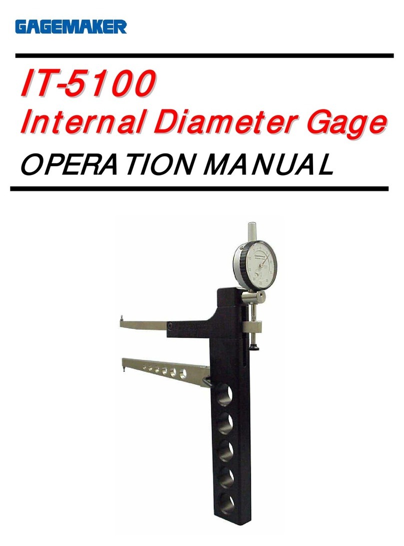
GAGEMAKER IT-5100 User manual

GAGEMAKER
GAGEMAKER MIC TRAC MT-3000 User manual

GAGEMAKER
GAGEMAKER LG-6001 User manual

GAGEMAKER
GAGEMAKER MIC TRAC MT-3000 User manual

GAGEMAKER
GAGEMAKER PD-8000-RSC User manual