manuals.online logo
Brands
  1. Home
  2. •
  3. Brands
  4. •
  5. Gaggenau
  6. •
  7. Ventilation Hood
  8. •
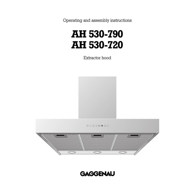
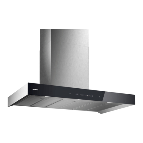
  9. Gaggenau AH600790 Product guide

Gaggenau AH600790 Product guide

Operating and asse bly instructions
H 600-790
Extractor hood
00
1
2
3
AH 600-790
1
Preface
Safety notes Page 3
1. Important notes Page 4-5
1.1 For your safety Page 4
1.2 Operating for the first ti e Page 5
1.3 About use Page 5
2. Structure and operating principle Page 6-7
2.1 Structure of the appliance Page 6
2.2 Accessories/special accessories Page 6
2.3 Operating principle Page 7
3. Operation Page 8-9
3.1 Switching on and off Page 8
3.2 Special functions Page 9
4. Cleaning and care Page 10-11
5. Maintenance Page 12
6. ssembly instructions Page13-19
6.1 Technical data Page 13
6.2 Installation Page 14-19
2
Preface
With your new extractor hood, working in the
kitchen will be even more fun.
The appliance offers you a nu ber of
advantages:
– effective extraction thanks to the so-called
“Coanda effect”
– low operating noise
To ensure that you will be able to use this appli-
ance in all its diversity, read through the operating
and asse bly instructions conscientiously before
operating it for the first time. The instructions
contain important notes on use, installation and
aintenance of the appliance.
On the following page you will find important
notes on safety and operation. These will serve
to ensure your personal safety and the lasting
value of your appliance.
You will find notes on Page 5 that you ought to
observe before operating the appliance for
the first time.
The chapters entitled “Structure and operating
principle” and “Operation” will tell you all the
things your extractor hood is capable of doing
and how the appliance is operated.
Tips and hints in the chapter entitled “Cleaning
and care” will ake sure that your appliance will
stay operable and beautiful for a long ti e.
nd now we wish you lots of fun with your
new extractor hood.
0
2
3
1
0
Fig. 1
W RNING - TO REDUCE THE RISK OF FIRE,
ELECTRIC SHOCK, OR INJURY TO PERSONS,
OBSERVE THE FOLLOWING:
a.) Use this unit only in the anner intended by the
anufacturer. If you have questions, contact
the anufacturer.
b.) Before servicing or cleaning unit, switch power
off at service panel and lock the service
disconnecting eans to prevent power fro
being switched on accidentally. When the
service disconnecting eans cannot be locked,
securely fasten a pro inent warning device,
such as a tag, to the service panel.
C UTION:
FOR GENERAL VENTILATION USE ONLY. DO NOT
USE TO EXHAUST HAZARDOUS OR EXPLOSIVE
MATERIALS AND VAPORS.
W RNING - TO REDUCE THE RISK OF
R NGE TOP GRE SE FIRE.
a.) Never leave surface units unattended at high
settings. Boilovers cause s oking and greasy
spillovers that ay ignite. Heat oils slowly on low
or ediu settings.
b.) Always turn hood ON when cooking at high heat
or when cooking fla ing foods.
c.) Clean ventilating fans frequently. Grease should
not be allowed to accu ulate on fan or filter.
d.) Use proper pan size. Always use cookware
appropriate for the size of the surface ele ent.
W RNING - TO REDUCE THE RISK OF INJURY
TO PERSONS IN THE EVENT OF R NGE
TOP GRE SE FIRE, OBSERVE THE
FOLLOWING:
a.) SMOTHER FLAMES with a close-fitting lid,
cookie sheet, or etal tray, then turn off the
burner. BE CAREFUL TO PREVENT BURNS. If the
fla es do not go out i ediately, EVACUATE
AND CALL THE FIRE DEPARTMENT.
b.) NEVER PICK UP A FLAMING PAN - You ay be
burned.
c.) DO NOT USE WATER, including wet dishcloth or
towels - a violent stea explosion will result.
d.) Use an extinguisher ONLY if:
1. You know you have Class ABC extinguisher,
and you already know how to operate it.
2. The fire is s all and contained in the area
where it started.
3. The fire depart ent is being called.
4. You can fight the fire with your back to an exit.
Safety notes
3
Read nd Save These Instructions.
4
1. I portant notes
1.1 For your safety
–Damaged appliances ust not be operated.
– The appliance ust only be connected by an
authorised specialist, paying attention to
the relevant regulations of the power supply
co panies and the regional construction
regulations.
lso observe the assembly instructions!
–Connecting cables ust not co e into contact
with hot cooking surfaces.
–Do not operate the extractor hood without
inserted la ps.
– Never operate the appliance without a grease
filter.
–Hazardous or explosive substances and
vapours ust not be extracted!
–The user is responsible for expert use and the
perfect condition of the appliance.
– Only ever operate the appliance under super-
vision.
–Caution! Over-greased filters are a fire risk!
Only ever deep-fry under the extractor under
constant supervision. Pay attention to cleaning
the grease filter on a regular basis.
–Fire risk! Do not fla bé eals under the
extractor hood!
– Operation of the extractor hood above a hearth
for solid fuels (coal or wood etc.) is only partly
per itted.
–Gas appliances ay only be used under the
extractor hood when pots and pans are placed
on the !
– When using more than 3 gas-operated rings
at the sa e ti e, please operate the extractor
hood at level 2 or higher. This prevents a build-
up of heat in the appliance.
–Do not place any heavy objects on the appli-
ance; this will have a detri ental effect on
functioning.
–Do not clean the appliance with a stea
cleaning apparatus or with water pressure
because this poses a risk of short-circuits.
– Isolate the appliance fro the ains during
every maintenance operation. To do this,
actuate the corresponding fuse.
–Repairs ust be carried out by authorised
specialists, thus ensuring electrical safety.
–No warranty claims can be lodged in the
event of damage caused by failure to observe
these instructions.
– Adequate inco ing air ust be ensured if a
wood, coal, gas or oil heater or an open hearth is
operated in the sa e roo as the one in which
the hood is installed.
– Safe operation is possible whenever the partial
vacuu in the place where the firing equip-
ment is installed does not exceed 4 Pa
(0.04 bar). This can be achieved whenever
the air needed for co bustion is able to enter
through openings that cannot be sealed, for
exa ple in doors, windows, inco ing/exhaust
air wall boxes or other technical eans.
– If the appliance is to be operated only with the
window open (to ensure adequate inco ing
air), you can use the window switch.
A switch (nor ally open) is fitted on the window.
On the appliance, this switch is connected to the
window switch ter inal on the ain electronics.
The appliance can now only be operated when
the window is open.
Important: the window switch ust only be
connected by an authorised specialist.
Note: The light function works without
restriction.
–fter a power failure, the extactor will not go
on again auto atically. You can reco ence
operation by turning a knob or by pressing any
key.
Technical modifications reserved.
1.2 Operating for the first time
Before operating the appliance for the first ti e,
please pay attention to the following notes:
–The appliance ust be installed and connected
by a specialist before it is operated for the first
ti e.
–The rating plate for this appliance is included
with the instructions on a separate sheet. Store
the rating plate in the sa e location as your
operating and asse bly instructions. You need
the rating plate for possible da age and
warranty cases.
–Conscientiously read through the operating
and asse bly instructions before operating the
appliance for the first ti e.
–Remove the packaging fro the appliance and
dispose of it properly. Pay attention to the fact
that there are accessories in the packaging.
Keep packaging ele ents out of the reach of
children!
–Thoroughly clean the appliance before using it
for the first ti e. (see chapter entitled “Cleaning
and care”).
–Before operating the appliance for the first
ti e, check that the ains connection is in
proper working order.
1.3 bout use
–The appliance is intended solely for use in the
household and ust not be put to any other uses.
–In the event of malfunctions, first of all check
the household fuses. If the proble has nothing
to do with the power supply, please contact your
specialist dealer or your local Gaggenau after-
sales service.
5
6
2. Structure and operating principle
2.1 Structure of the appliance
2.2 ccessories/special accessories
You can order the following special accessories:
– Activated charcoal filter: KF 600-090
– Back draught flap RK 040-150: Back draught
flap for insertion in the extractor’s blow-out
opening
– Flexible alu iniu pipe R 040-150:
DN 150 up to 3.5 / 11’ 5/8”
length with 2 hose cla ps
1Display
2Glass plates
3Air duct
4Control panel
5Grease filter key
6Ventilation level display
7“Coanda level” key
8“Light” control knob
9“Ventilation level” control knob
10 “After-running” key
11 “After-running” sy bol
12 “Grease filter saturation” sy bol
13 “Coanda level” sy bol
14 “Intensive level” sy bol
15 “Intensive level” key
Installation accessories:
Exhaust air:
Ventilation duct for ceiling heights of
2.35 - 2.66 / 7’ 7” - 8’ 6”: LK 600-010
Ventilation duct for ceiling heights of
2.66 - 3.00 / 8’ 6” - 9’ 9”: LK 600-020
ir recirculation:
Ventilation duct for ceiling heights of
2.43 - 2.66 / 7’ 10” - 8’ 6”: LK 600-110
Ventilation duct for ceiling heights of
2.66 - 3.00 / 8’ 6” - 9’ 9”: LK 600-120
00
1
2
3
Fig. 2
00
1
2
3
Fig. 3
567 8 9
10 11 12 13 14 15
3
2
4
2
1
2.3 Operating principle
This extractor hood swiftly and silently extracts
all odours produced while cooking. You can set
different intensity levels depending on the intensity
of odours.
The exhaust air first passes through the integrated
grease filter. The grease filter intercepts and traps
the grease and odour particles in the air.
In the exhaust air mode:
The fan in the extractor hood sucks in the kitchen
vapours and passes the through the grease filter
to outdoors. The grease filter absorbs the greasy
co ponents in the kitchen vapours (see Fig. 4).
In the air recirculation mode:
An activated charcoal filter (special accessory)
ust be installed. The fan in the extractor hood
sucks in kitchen vapours and returns the to
the kitchen after purification in the grease and
activated charcoal filter. The grease filter absorbs
the greasy co ponents in the kitchen vapours.
The activated charcoal filter binds odour particles
(see Fig. 5).
The “Coanda effect”
Kitchen vapours are extracted even better with the
“Coanda effect”. By eans of an additional otor,
kitchen vapours are passed swiftly and effectively
into the hood’s extraction zone. An additional fan
on the front edge of the kitchen extractor hood
generates an air strea that is diverted around a
cylinder towards the rear. This ensures that kitchen
vapours are routed co pletely into the extractor
hood’s filter area (see Fig. 6).
7
Fig. 4
Fig. 5
Fig. 6
8
3.1 Switching on and off
Switching on
– Turn the “Ventilation level” control knob to the
ventilation level you require (Fig. 7).
– The set level is displayed.
Switching off
– Turn the “Ventilation level” control knob to
the 0 position (Fig. 8).
– The set level 0 is displayed for a few seconds.
Note:
The light can be switched on and off at any ti e.
To do this, turn the “Light” control knob to the
(Light) position.
Switching on the Coanda level
– Turn the “Ventilation level” control knob to the
level you require.
– Press the Coanda level key.
– The level you have set and the Coanda level
sy bol appear on the display (Fig. 9).
Note: You can change to any ventilation level, and
the Coanda level re ains set.
Switching off the Coanda level:
– Press the “Coanda level” key or turn the
“Ventilation level” knob to the 0 position.
3. Operation
00
1
2
3
Fig. 7
00
1
2
Fig. 8
Fig. 9
00
1
2
3
9
3.2 Special functions
Intensive level
You should select the intensive level when
browning and frying in an open pan.
Switching on: (Fig. 10)
– Turn the control knob to a ventilation level (1-3).
– Press the intensive level key. The intensive level
sy bol appears on the display. The previously
selected ventilation level flashes on the display.
After a few inutes, the appliance switches
back auto atically to the previously selected
ventilation level.
or
– Press the intensive level key. The intensive level
sy bol appears on the display. The appliance
is now operated at the intensive level for a few
inutes and then switches off auto atically.
Ending the intensive level prematurely:
– Turn the “Ventilation level” knob to the 0 position
or
– turn the “Ventilation level” knob to any level or
– press the intensive level key once again.
fter-running
Switching on:
– Press the (After-running) key.
– The (After-running) sy bol and ventilation
level 2 light up on the display (Fig. 11).
or
– Turn the “Ventilation level” control knob to any
level.
– Press the (After-running) key.
– The (After-running) sy bol and the set
ventilation level light up on the display (Fig. 12).
– The extractor hood continues running for
10 inutes.
Switching off:
– Turn the “Ventilation level” control knob to the 0
position.
or
– Press the (After-running) key.
00
1
2
3
Fig. 10
Fig. 11
Fig. 12
00
1
2
3
Cleaning the grease filters:
The (Grease filter saturation) sy bol flashes
on the display after an operating ti e of 30 hours.
Flashing of this sy bol signals to you that the
grease filters have to be cleaned. The grease filters
can be cleaned at any ti e, even if the (grease
filter saturation) sy bol does not flash. The etal
filters can be re oved easily for cleaning.
Proceed as follows:
– Grip the grease filter handles and press the
slide towards the rear.
– Pull the grease filter out of its ount in the
downward direction (Fig. 13).
– Repeat the operation with the other grease
filters.
You can clean the etal grease filters in a dish-
washer at a axi u te perature of 65°C / 150 °F.
Place the grease filters vertically in the dishwasher
to ensure that no food re ainders will stay on the .
Slight discoloration can occur when cleaning the
grease filters in a dishwasher.
When replacing the grease filters, wipe out
the inner part of the housing with hot detergent
solution.
Reinsert the grease filters in the hood after
cleaning. Install the in the reverse order to
re oval.
Press the (Grease filter) key to set the elapsed
hours counter to zero; the (Grease filter) sy bol
stops flashing.
Do not clean the appliance with a stea cleaning
apparatus or with water pressure because this
poses a risk of short-circuits.
10
4. Cleaning and care
Note:
The handles of the grease filters ust be visible
after installation. They can no longer be re oved
if the handles are in the inner part of the housing.
Fig. 13
ir recirculation
If, when purchasing the extractor hood, you have
decided in favour of the air recirculation ode,
the activated charcoal filter KF 600-090 ust be
replaced after a certain a ount of hood operation.
Note: The activated charcoal filter is not included
in the scope of delivery of the hood.
Activated charcoal filters do not contain any
polluting substances. Old activated charcoal filters
can be disposed of as do estic waste. If used once
daily, the activated charcoal filter ust be replaced
approxi ately once to twice every year. First
re ove the grease filter. Press out the two tabs in
the downward direction and re ove the activated
charcoal filter fro the hood in the downward
direction (see Fig. 14). Replace the old activated
charcoal filter by the new one. Install in the reverse
order.
Cleaning the extractor hood
Clean the stainless steel parts of the extractor
hood with ild rinsing detergent and apply
stainless steel care agent to the etal surfaces
using a soft cloth.
Clean the two glass plates in a dishwasher.
Do not use any strong or caustic cleaning agents or
brushes and abrasive cleaner.
Do not use any abrasive sponges either. Use
co ercially available window cleaner and apply
it to a soft, oist cloth.
Only clean the switch panel with a soft cloth. Do
not use any cleaning agent as it ight be agressive
to the inscription arkings.
11
Fig. 14
12
The appliance must be disconnected from the
power supply during all repair work.
If the appliance does not function correctly, check
the fuses first.
If the power supply is functioning correctly, but your
appliance still does not work, please contact your
Gaggenau dealer who will provide you with the
address and telephone nu ber of your nearest
anufacturer’s authorized service agent or contact
Gaggenau US on (800) 828-9165. Specify the
appliance type (see rating plate).
Repairs ay only be carried out by authorised
technicians, in order to guarantee the safety of the
appliance.
Unauthorised ta pering with the appliance will
invalidate any warranty clai s.
Only ever use original spare parts.
Lamp replacement
Caution: Disconnect the power supply before
replacing la ps!
Caution: La ps ay still be hot shortly after use!
Risk of burns.
– Re ove the grease filters.
– Re ove the screws on the la p cover. The la p
cover tilts down and cannot be re oved fro
the appliance (Fig. 15).
– Turn the la p to the left and re ove the la p
(Fig. 16).
Defective la ps ust only be replaced by la ps
of the sa e type (Cool Bea )! You can obtain
the original spare part (No. 03602611) fro trade
dealers or via Gaggenau after-sales service.
Inserting the lamp
– Insert the la p and turn it to the right.
– Screw down the la p cover again.
– Connect the appliance to the ains again.
5. Maintenance
Fig. 16
Fig. 15
13
6.1 Technical data
Weight: 28 kg
Di ensions: 898 x 520 / 2’ 111/2” - 1’ 1/2”
Electrical connection
Pay attention to the rating plate data.
The appliance ust only be connected by an
authorised specialist. The specialist is respon-
sible for perfect functioning of the appliance at its
installation location. He ust explain the operating
principle of the appliance to the user with refe-
rence to the operating instructions. He ust explain
to the user how the appliance can be isolated fro
the ains whenever required.
Connection possibilities
The extractor hood was conceived for the exhaust
air or air recirculation ode. The exhaust air can be
routed into a separate exhaust air shaft or directly
into the open through the outside wall.
It ust be possible to isolate all poles of the
appliance fro the ains by way of the do estic
fuse, or by eans of accessible isolating device
with a contact gap of at least 3 .
6. Asse bly instructions
AH 600-790 FD xxxx xxxx
AC 120V 60Hz 345W xxxx
160W 35W 3x50W 3A
6.2 Installation
W RNING - TO REDUCE THE RISK OF FIRE,
ELECTRIC SHOCK, OR INJURY TO PERSONS,
OBSERVE THE FOLLOWING:
a.) Installation work and electrical wiring ust be
done by qualified person(s) in accordance with
all applicable codes and standards, including
fire-rated construction.
b.) Sufficient air is needed for proper co bustion
end exhausting of gases through the flue
(chi ney) of fuel burning equip ent to prevent
back drafting. Follow the heating equip ent
anufacturer’s guideline and safety standards
such as those published by the National Fire
Protection Association (NFPA), and the A erican
Society for Heating, Refrigeration and Air
Conditioning (ASHRAE), and the local code
authorities.
c.) When cutting or drilling into wall or ceiling, do
not da age electrical wiring and other hidden
utilities.
d.) Ducted fans ust always be vented to the
outdoors.
e.) If this unit is to be installed over a tub or shower,
it ust be arked as appropriate for the appli-
cation and be connected to a GFCI (Ground
Fault Circuit Interrupter) - protected branch
circuit.
f.) NEVER place a switch where it can be reached
fro a tub or shower.
W RNING:
To reduce the risk of fire, use only etal ductwork.
The applicable regulations of the energy supply
co panies and the regional construction
regulations ust be observed when installing
the hood.
The ini u distance fro the worktop to the
botto edge of the wall hood is for electrical
appliances 600 / 24” and for gas appliances
670 / 261/2”.
The wall hood was conceived for the exhaust air
or air recirculation mode. The exhaust air can be
routed into a separate exhaust air shaft or directly
into the open through the outside wall.
It is not allowed to pass the exhaust air into a flue
or exhaust air chi ney that is in operation or into a
shaft that is linked to the heating base ent. Consult
the chi ney sweep responsible for your district
whenever you wish to pass the exhaust air into a
chi ney that is not in operation.
During the course of planning, a chi ney sweep
ust be consulted if a roo air-dependent hearth
is operated in the sa e roo as the one in which a
hood is operated in the exhaust air ode. Adequate
inco ing air ust be ensured. The applicable
construction and safety regulations ust be
observed.
Adequate inco ing air ust be ensured if a wood,
coal, gas or oil heater or an open hearth is operated
in the sa e roo as the one in which the hood is
installed.
Safe operation is possible whenever the partial
vacuu in the place where the firing equip ent
is installed does not exceed 4 Pa (0.04 bar).
This can be achieved whenever the air needed for
co bustion is able to enter through openings that
cannot be sealed, for exa ple in doors, windows,
inco ing/exhaust air wall boxes or other technical
eans.
14
Flexible alu iniu pipes, corrosion-protected
sheet etal pipes and exhaust air pipes whose
aterial confor s to fire B1 in accordance with
DIN 4102 can be used. Exhaust air pipes should
have a no inal dia eter of 150 / 6”.
Pay particular attention to ensuring that
– the exhaust air ducts and pipes are kept as short
as possible
– the pipes are not laid at an acute angle, but as
bends and that they are inserted into the shaft at
an inclined upward angle and
– there are no cross-sectional constrictions in the
upward direction (this reduces the volu e flow).
As standard, the blow-out opening of the wall hood
is in the upward direction.
To pass exhaust air through the outer wall, we
reco end the use of our telescopic wall box
TM 150-045 (Ø 150 / 6”).
Note:
To prevent the ingress of water, e.g. condensate or
rain water fro an uncovered exhaust air shaft, our
condensate separator RV 060-150 ust be installed
in the exhaust air line. The condensate separator
ust still be acciessible after installation.
ir recirculation
You need the following accessories to install the
air recirculation hood:
–KF 600-090: activated charcoal filter:
Depending on the ceiling height, the following duct
units are at your disposal for air recirculation:
–LK 600-110: Ventilation duct for a ceiling height
of 2.43 - 2.66 / 7’ 10” - 8’ 6”
–LK 600-120: Ventilation duct for a ceiling height
of 2.66 - 3.00 / 8’ 6” - 9’ 9”
The di ensions above refer to a distance of 1.60 /
5’ 5/16” fro the floor to the botto edge of the hood.
Exhaust air operation
Depending on the ceiling height, the following duct
units are at your disposal for exhaust air operation:
–LK 600-010: Ventilation duct for a ceiling height
of 2.35 - 2.66 / 7’ 7” - 8’ 6”
–LK 600-020: Ventilation duct for a ceiling height
of 2.66 - 3.00 / 8’ 6” - 9’ 9”
The di ensions above refer to a distance of 1.60 /
5’3” fro the floor to the botto edge of the hood.
If required, a side outlet for the air duct is available
at an extra charge.
15
520
(20 15 /
32 ”)
260
(10
1
/
4
”)
150
(6”)
480
(18 7/
8”)
1600
(5’3”)
522.5
(
20
9
/
16
”)
min. 600
(24”)
over electric cooker
min. 670
(26
1
/
2
”)
over gas cooker
Exhaust air: 750 - 1400
(18
5
/
8
”-55
1
/
8
”)
Air recirculation: 825 -
1400
(32
1
/
2
”-55
1
/
8
”)
Hood height
Exhaust air: 2.35 - 3.0
(18 5/
8” - 55 1/
8”)
Air recirculation: 2.43 - 3.0
(32 1/
2” - 55 1/
8”)
Ceiling height
Sus-
pension
Fig. 17
Proceed as follows:
Exhaust air operation:
– Fro the botto edge of the hood, ark a center
line on the wall.
– With the aid of the drilling te plate, ark the
positions of the screws on the wall. Mark the
contour of the hook-in area. This will ake it
easier to hook in the hood (Fig. 18).
– Pay attention to the ini u clearance of 600 /
24” for electric cookers and 670 / 261/2” for
gas cookers. The botto edge of the te plate
corresponds to the botto fro edge of the hood.
– Using the drilling te plate, drill the 6 holes for
the hood (area I of the drilling te plate) and the
two holes for suspending the chi ney (area II of
the drilling te plate). In the top two securing
holes for the hood, fix the two hooks ewith the
countersunk screws d. Make sure that the hooks
lie flatly on the wall. In certain circu stances you
ay have to countersink the drill holes. Fit the
included dowels ain the other drill holes.
Note: Pay attention to any special accessories that
you ay have to fit.
– Screw on the retaining bracket for the chi ney
paneling.
– Detach the grease filters.
– Unscrew the two black plates on the left and right
of the chi ney.
– Hang the hood on the two hooks. Adjust the
suspended ele ent with the recessed head
screw and align the hood using a spirit level
(Fig. 19).
16
448
137
625
270
300
(11
13
/
16
")
15 (
19
/
32
")
310
mind. 600 Elektro
mind. 670 Gas
230
(12
3
/
16
")
(9
1
/
16
")
(24
5
/
8
")
(17
5
/
8
")
(5
13
/
32
")
(10
5
/
8
")
Fig. 18
Fig. 19
min. 600
(24”)
electric
min. 670
(26
1
/
2
”)
gas
Important: Before arking the securing holes,
ake sure that no electricity or water lines or
other lines are laid at the drilling points in the wall.
– Secure the hood to the wall using the 4 screws b
with shi s c(Fig. 20).
– Establish the pipe connection.
– Establish the electrical connection.
– Extract the protective file fro the chi ney
paneling.
Note: Avoid da aging the sensitive stainless steel
surfaces.
– Join the chi ney shoe with the chi ney base
using the 6 screws (3.5 x 9.5 ) (Fig. 21).
– Fit the top of the chi ney into the base. Make
sure that the fastening holes on the side are at the
top.
– Secure the top duct unit with 2 screws on the
ceiling holder.
– Pull the shoe down into its final position
(Fig. 22).
Note: Avoid scratches when fitting the ele ents
into one another by placing the asse bly te plate,
for exa ple, over the edge of the botto chi ney
paneling to protect it.
– Reinsert the grease filters.
– Again screw in the two black plates on the left
and right of the chi ney.
– Place the glass plates on the black plates.
17
Fig. 20
Fig. 21
Fig. 22
Recirculation air operation
– Fro the botto edge of the hood, ark a center
line on the wall.
– With the aid of the drilling te plate, ark the
positions of the screws on the wall. Mark the
contour of the hook-in area. This will ake it
easier to hook in the hood (Fig. 23).
– Pay attention to the ini u clearance of 600 /
24” for electric cookers and 670 / 261/2” for
gas cookers. The botto edge of the te plate
corresponds to the botto fro edge of the hood.
– Using the drilling te plate, drill the 6 holes for the
hood (area I of the drilling te plate) and the two
holes for suspending the chi ney (area II of the
drilling te plate). In the top two securing holes for
the hood, fix the two hooks ewith the countersunk
screws d. Make sure that the hooks lie flatly on the
wall. In certain circu stances you ay have to
countersink the drill holes. Fit the included dowels
ain the other drill holes.
Note: Pay attention to any special accessories that
you ay have to fit.
– Detach the grease filters.
– Unscrew the two black plates on the left and right
of the chi ney.
– Hang the hood on the two hooks. Adjust the
suspended ele ent with the recessed head screw
and align the hood using a spirit level (Figure 19).
– Secure the hood to the wall using the 4 screws b
with shi s c.
– Screw the retaining bracket for the chi ney
paneling onto the wall together with the two
retaining brackets for the housing (air guidance)
(Fig. 24).
18
448
137
625
270
300
(11
13
/
16
")
15 (
19
/
32
")
310
mind. 600 Elektro
mind. 670 Gas
230
(12
3
/
16
")
(9
1
/
16
")
(24
5
/
8
")
(17
5
/
8
")
(5
13
/
32
")
(10
5
/
8
")
Fig. 23
Fig. 24
min. 600
(24”)
electric
min. 670
(26
1
/
2
”)
gas
– Screw together the air guidance housing and
screw it onto the two retaining brackets (Fig. 25).
– Establish the pipe connection between the air
connection piece and the air guidance housing.
– Establish the electrical connection.
– Stick the included sealing strips (8 strips) around
the air slots on the top chi ney paneling.
– Re ove the protective foil fro the chi ney
paneling.
Note: Avoid da aging the sensitive stainless steel
surfaces.
– Join the chi ney shoe with the chi ney base
using the 6 screws (3.5 x 9.5 ) (Fig. 26).
– Fit the top of the chi ney into the base. Make
sure that the fastening holes on the side are at the
top.
– Secure the top duct unit with 2 screws on the
ceiling holder.
– Pull the shoe down into its final position
(Fig. 27)
Note: Avoid scratches when fitting the ele ents
into one another by placing the asse bly te plate,
for exa ple, over the edge of the botto chi ney
paneling to protect it.
– Make sure that an activated charcoal filter is
installed (see page 10).
– Reinsert the grease filters.
– Again screw in the two black plates on the left
and right of the chi ney.
– Place the glass plates on the black plates.
03.6028.27ind01 en 10.00 SK 19
Fig. 25
Fig. 26
Fig. 27

Other Gaggenau Ventilation Hood manuals

Gaggenau AH 900 User manual

Gaggenau

Gaggenau AH 900 User manual

Gaggenau VL 414 712 User manual

Gaggenau

Gaggenau VL 414 712 User manual

Gaggenau AL 400 User manual

Gaggenau

Gaggenau AL 400 User manual

Gaggenau AI 280720 User manual

Gaggenau

Gaggenau AI 280720 User manual

Gaggenau AW 442 190 CN User manual

Gaggenau

Gaggenau AW 442 190 CN User manual

Gaggenau AW240120 User manual

Gaggenau

Gaggenau AW240120 User manual

Gaggenau AW 400720 User manual

Gaggenau

Gaggenau AW 400720 User manual

Gaggenau AC2001.1 User manual

Gaggenau

Gaggenau AC2001.1 User manual

Gaggenau AT 400-700 User manual

Gaggenau

Gaggenau AT 400-700 User manual

Gaggenau AC250190 User manual

Gaggenau

Gaggenau AC250190 User manual

Gaggenau AH 590-720 Product guide

Gaggenau

Gaggenau AH 590-720 Product guide

Gaggenau AL200180 User manual

Gaggenau

Gaggenau AL200180 User manual

Gaggenau AA 490 710 User manual

Gaggenau

Gaggenau AA 490 710 User manual

Gaggenau VL 040/041 115 User manual

Gaggenau

Gaggenau VL 040/041 115 User manual

Gaggenau AI 540-720 Product guide

Gaggenau

Gaggenau AI 540-720 Product guide

Gaggenau AW 281120 Assembly instructions

Gaggenau

Gaggenau AW 281120 Assembly instructions

Gaggenau AH 400-731 User manual

Gaggenau

Gaggenau AH 400-731 User manual

Gaggenau VL040-707 Product guide

Gaggenau

Gaggenau VL040-707 Product guide

Gaggenau AI280120 User manual

Gaggenau

Gaggenau AI280120 User manual

Gaggenau AI480180 User manual

Gaggenau

Gaggenau AI480180 User manual

Gaggenau AI 442 120 CN User manual

Gaggenau

Gaggenau AI 442 120 CN User manual

Gaggenau AH 600-190 Product guide

Gaggenau

Gaggenau AH 600-190 Product guide

Gaggenau AH600990 Product guide

Gaggenau

Gaggenau AH600990 Product guide

Gaggenau AW 260-170 Assembly instructions

Gaggenau

Gaggenau AW 260-170 Assembly instructions

Popular Ventilation Hood manuals by other brands

GLOBALO Loteo Series Operating and installation instructions

GLOBALO

GLOBALO Loteo Series Operating and installation instructions

AEG mintie ECU4 owner's manual

AEG

AEG mintie ECU4 owner's manual

Novy Flat'line 7640 user manual

Novy

Novy Flat'line 7640 user manual

Whirlpool RH2000 Series installation instructions

Whirlpool

Whirlpool RH2000 Series installation instructions

KOBE IN2636SQB-1200 Installation instructions and operation manual

KOBE

KOBE IN2636SQB-1200 Installation instructions and operation manual

Franke 1240B-10 User instructions

Franke

Franke 1240B-10 User instructions

Futuro Futuro Folio Installation & user manual

Futuro Futuro

Futuro Futuro Folio Installation & user manual

Bartscher 700-W1600 Original instruction manual

Bartscher

Bartscher 700-W1600 Original instruction manual

Komfovent 1224G-12 User instructions

Komfovent

Komfovent 1224G-12 User instructions

Pelgrim SLK680 manual

Pelgrim

Pelgrim SLK680 manual

Broan Antero CLSC230WW Installation use and care manual

Broan

Broan Antero CLSC230WW Installation use and care manual

Electrolux LFV316K user manual

Electrolux

Electrolux LFV316K user manual

Whirlpool Ventilation Hood Installation and use guide

Whirlpool

Whirlpool Ventilation Hood Installation and use guide

Zephyr Tornado Mini AK8400BS Use, care and installation guide

Zephyr

Zephyr Tornado Mini AK8400BS Use, care and installation guide

Schweigen WM-LIN9S instruction manual

Schweigen

Schweigen WM-LIN9S instruction manual

Ancona Pro Insert 28 User's manual & installation instructions

Ancona

Ancona Pro Insert 28 User's manual & installation instructions

Baumatic AS7.2SS Studio Solari manual

Baumatic

Baumatic AS7.2SS Studio Solari manual

Havis PT-A-920 Install instructions

Havis

Havis PT-A-920 Install instructions

manuals.online logo
manuals.online logoBrands
  • About & Mission
  • Contact us
  • Privacy Policy
  • Terms and Conditions

Copyright 2025 Manuals.Online. All Rights Reserved.