Ganz PixelPro GXi Series User manual

10-2013-A 1

10-2013-A 2
Precaution
Please read this manual carefully before installing the unit.
Never disassemble the blade. Unauthorized disassembly may cause equipment failure
or damage to the unit.
Please do not install the blade and the rack in a place exposed to an excessive heat
source.
Do not operate the unit in environments beyond the specified temperature.
Refer to “Environment Condition”on “APPENDIX (A): SPECIFICATIONS”in this manual.
Before mounting the blade, check the power source to ensure that it is within the
specifications. Refer to “Electrical Characteristics”on “APPENDIX (A) :
SPECIFICATIONS”

10-2013-A 3
Table of Contents
Precaution................................................................................................................ 2
1. FEATURES............................................................................................................. 4
2. PACKAGE CONTENTS............................................................................................. 5
3. PART NAMES ........................................................................................................ 6
3.1. Blade................................................................................................................................... 6
3.2. Sub-rack.............................................................................................................................. 7
4. INSTALLATION ...................................................................................................... 8
4.1.Connectors .......................................................................................................................... 8
4.2.Inserting and ejecting a blade........................................................................................... 10
4.2.1. Inserting a blade........................................................................................................ 10
4.2.2. Ejecting a blade ......................................................................................................... 10
5. CONFIGURATION ................................................................................................ 11
5.1. Set up network environment ........................................................................................... 11
5.2. View video on web page .................................................................................................. 11
5.2.1. View video using IPAdmin Tool................................................................................. 11
5.2.2. View video using IP address ...................................................................................... 13
5.3. Reboot.............................................................................................................................. 13
5.4. Factory Default................................................................................................................. 13
APPENDIX (A): SPECIFICATIONS .............................................................................. 13
Summary ................................................................................................................................. 14
Electrical Characteristics ......................................................................................................... 14
Environment Condition ........................................................................................................... 15
Mechanical Condition ............................................................................................................. 15
APPENDIX (B): DIMENSIONS ................................................................................... 16
APPENDIX (C): HEXADECIMAL-DECIMAL CONVERSION TABLE.................................. 17
REVISION HISTORY ................................................................................................. 17

PixelPro GXi Series ZS1-4DB1 Installation Guide
10-2013-A 4
1. FEATURES
Main Feature
Compatible with 19’’/1U Aluminum Sub-Rack chassis, which supports up to 3 units
of 4 channel encoder blades
Identification of each sub-rack, each blade card, and each module unit (for easy
and quick maintenance)
Streaming
Dual streaming mode (such as different codec/resolution/bit rate and so on.)
De-interlacing on DSP
Burnt-in text supported
Unicast/Multicast supported
Video/Audio
Video compression: H.264/MJPEG, 25/30FPS@D1(PAL/NTSC)
Audio compression: G.711(µLaw)
Video Motion Detection supported
Audio Input/output supported (4/1ch)
Network
RTSP/ HTTP protocol supported
10/100 Base-T Ethernet
Additional Features
RS-485 supported
Digital Input / Output supported
Built-in Video Content Analysis (For each module)
SDK (Software Development Kit) provided
VCA (Video Content Analysis)
VCA Surveillance (Optional)
PixelPro GXi Series ZS1-4DB1 Installation Guide
10-2013-A 5
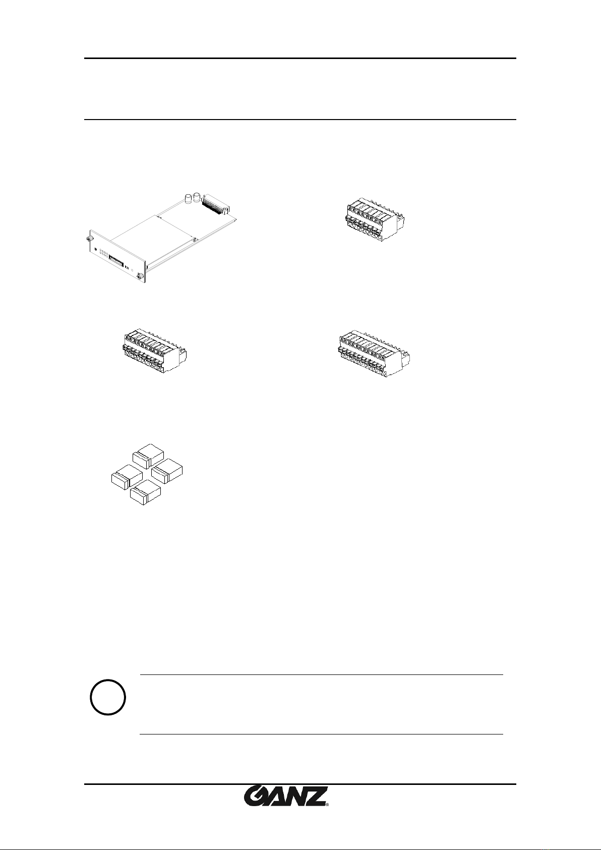
2. PACKAGE CONTENTS
Unpack carefully and handle the equipment with care. The packaging contains:
Encoder Blade
8 Pin terminal block
10 Pin terminal block
12 Pin terminal block
Jumper Cap x 4 ea
Note
i
The above contents are subject to change without prior notice.
PixelPro GXi Series ZS1-4DB1 Installation Guide
10-2013-A 6
3. PART NAMES
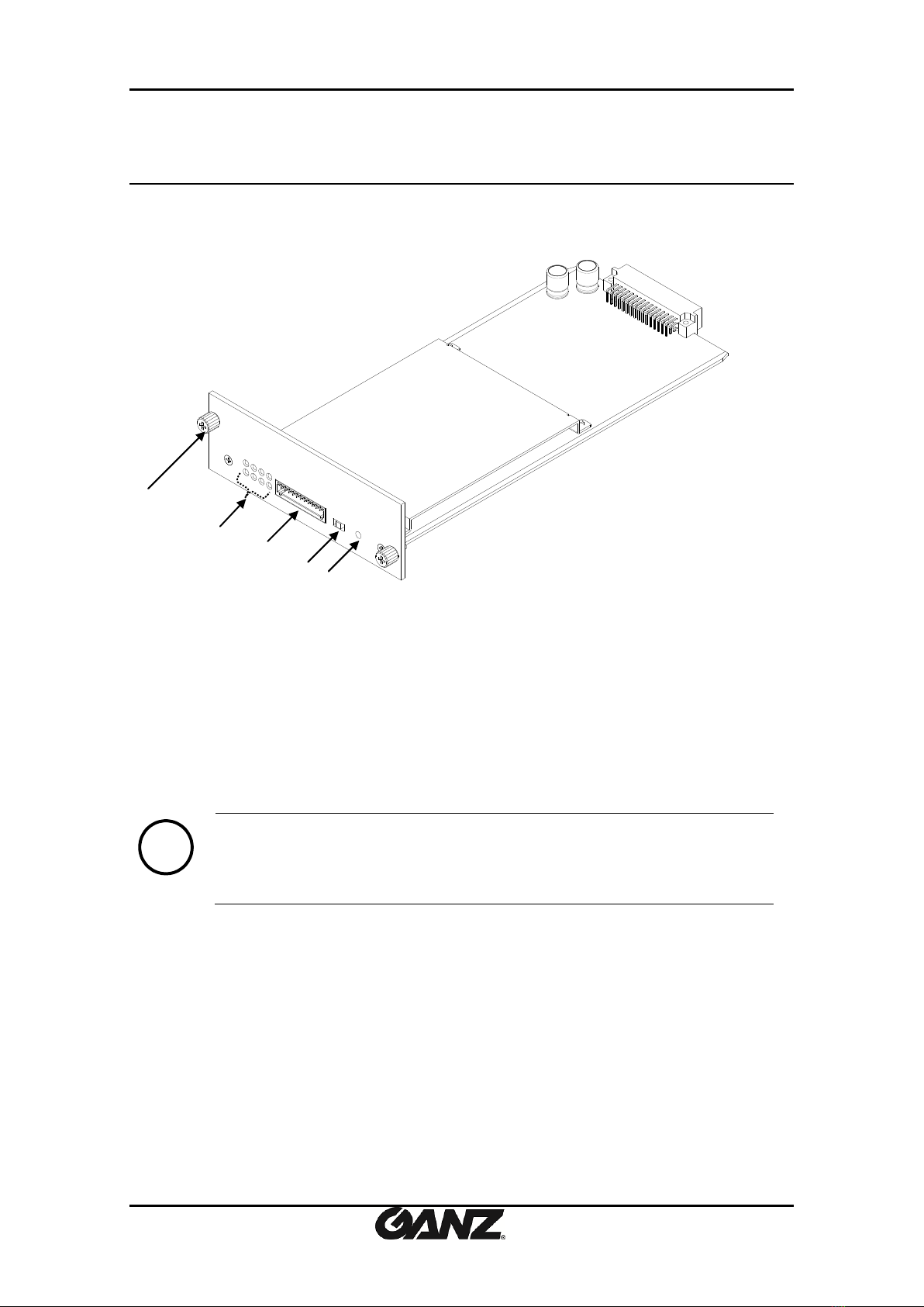
3.1. Blade
①Screw
This is used to fasten the blade to the rack chassis.
②System Status LEDs
The LEDs indicate certain system information.
Status: This LED lights up as orange and turns green when the modules are powered on.
Data: This LED lights up when the host system is turned on with a connection is made.
Note
i
The color of LEDs is subject to change according to the firmware version
③12 pin terminal blocks for D/I, D/O, audio
Refer to the section “4.1. Connectors”for more specific information.
④Video Input Configuration Switch
This switch enables video input and output to be turned on or off. No video comes in or out
with this switch off and only some test patterns will be displayed on the Webpage. You can
change the video standard format of the device by moving the switch to NTSC side or PAL side
as required. The device needs to be rebooted after moving the switch in order to apply the
change.
①
②
○
4
○
5
* Models herein and their appearance are subject to change without any prior notice.
③
10-2013-A 7
⑤Reset
Reboot the device system or reset the device to its Factory default settings. Refer to the
section “5.3. Reset” for more specific information.
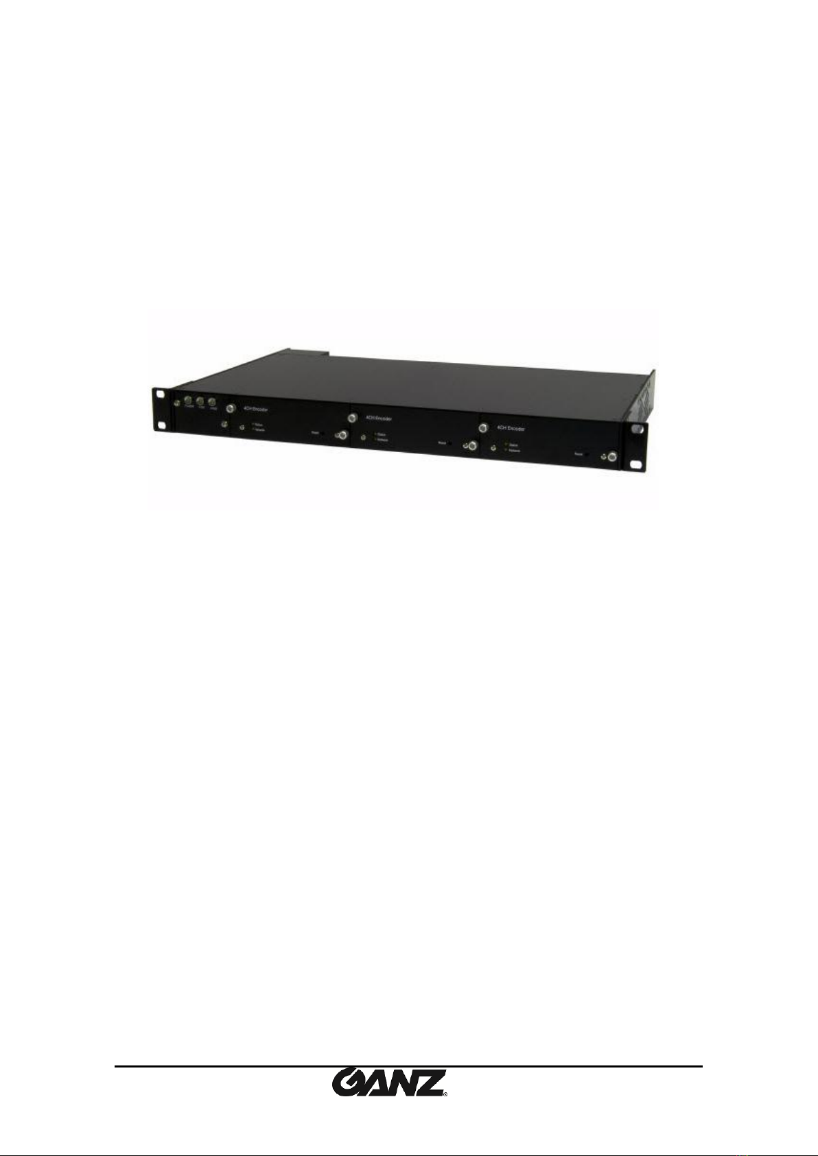
3.2. Sub-rack
The blade is designed for mounting in the sub rack chassis, which provides power and network
connectivity. This blade cannot be used apart from the sub-rack.
Specifications of 19’’/1U Sub-Rack Chassis
19” / 1U Aluminum Sub-Rack
Support up to 3 units of 4CH encoder blades (Total 12 channels @ D1)
Hot-swappable encoder blade
Identification of each Sub-Rack and each blade unit (for easy and quick
maintenance)
Temperature Sensor included
Detect power supplier unit operation (Self-diagnosing)
Detect fan unit operation (Self-diagnosing)
Applied device: 4CH encoder blades for H.264 (3 slot expansion supported model)
4CH encoder blades for MPEG-4 (3 slot expansion supported
model)
19’’/1U Sub-Rack Chassis
PixelPro GXi Series ZS1-4DB1 Installation Guide
10-2013-A 8
4. INSTALLATION
4.1.Connectors
Video connection
Connect the camera to the video input connectors on the back panel using 75 ohm video
coaxial cables with a BNC connector. Each of the connected video input channel can be looped
to other equipment (e.g. CRT monitor) through external video output connector.
Audio connection
Connect to the audio input device such as a microphone.
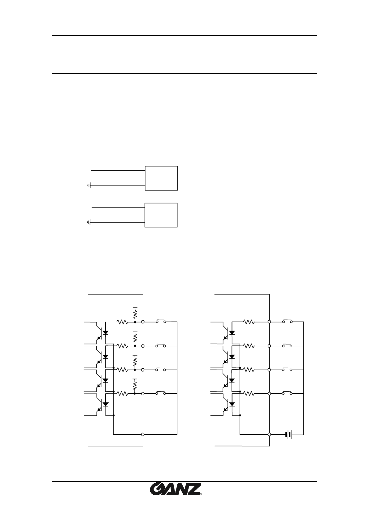
Sensor Input (D/I)
There are two sensor interface types –Voltage Type and Relay Type. The interface type can be
controlled by the software. Before connecting sensors, check driving voltage and output signal
type of the sensor. Since the connection is different according to sensor type, be careful to
connect the sensor.
Mic
Ain
Speaker
Aout
Relay Type
Voltage Type
DI 1
DI 2
COM
+
-
+5VDC
+
-
+
-
Output of
Sensor 1
Output of
Sensor 2
Internal
+
-
+
-
DI 3
DI 4
Output of
Sensor 3
Output of
Sensor 4
DI 1
DI 2
COM
+
-
+
-
Output of
Sensor 1
Output of
Sensor 2
Internal
+
-
+
-
DI 3
DI 4
Output of
Sensor 3
Output of
Sensor 4
+3.3V
+3.3V
+3.3V
+3.3V
1st
Module
2ND
Module
3rd
Module
4st
Module
1st
Module
2ND
Module
3rd
Module
4st
Module

PixelPro GXi Series ZS1-4DB1 Installation Guide
10-2013-A 9
Input voltage range: 0VDC minimum to 5VDC maximum, Max 50mA
Signal
Description
COM
Connect (-) cable of electronic power source for sensors to this port as shown
in the circuit above.
D1~D4
Connect output of sensors for each port as shown in the circuit above.
Caution
!
Do not exceed the maximum input voltage or relay rate.
Do not use voltage and relay type sensor together.
Alarm Output (D/O)
Only the relay type is supported.
Relay Rating: Max 24VDC 50mA
Caution
!
Do not exceed the maximum relay rating.
Relay Type
DO 1
DO 4
COM
Device
Device
Internal
DO 2
Device
Device
DO 3
1st
Module
2ND
Module
3rd
Module
4st
Module
PixelPro GXi Series ZS1-4DB1 Installation Guide
10-2013-A 10
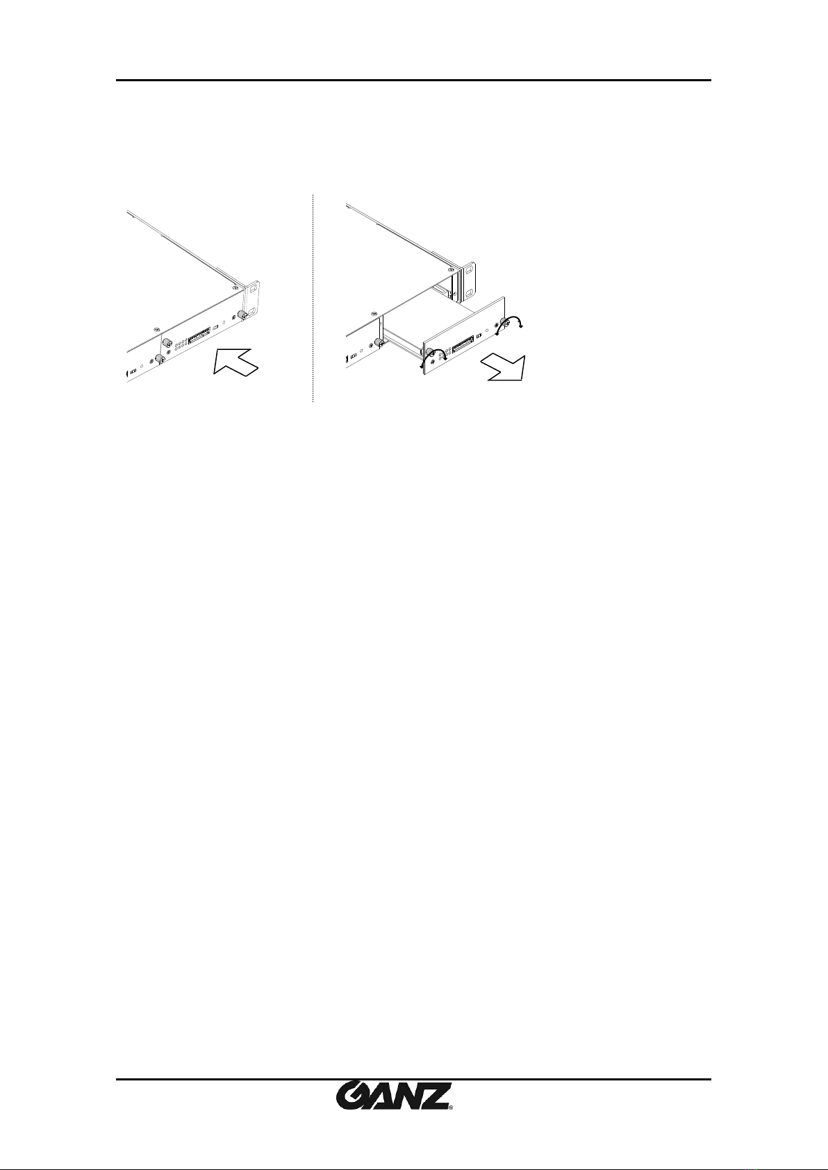
4.2.Inserting and ejecting a blade
4.2.1. Inserting a blade
*Remove a cover plate from the slot in which a blade will be mounted. This is done by
unfastening the screws with a screw driver on each side of the cover.
1. Insert the blade into the rack chassis. Make sure the blade is properly aligned with the
rail.
2. Push back the blade completely.
3. Tighten the screws by turning them clockwise.
4.2.2. Ejecting a blade
1. Unlock the two screws on both sides of the blade.
2. Grasp the blade and pull it out as shown in the above image
3. Remove the blade from the rack chassis.
Inserting a blade
Ejecting a blade
Unlock
Lock
Unlock
Lock
PixelPro GXi Series ZS1-4DB1 Installation Guide
10-2013-A 11
5. CONFIGURATION
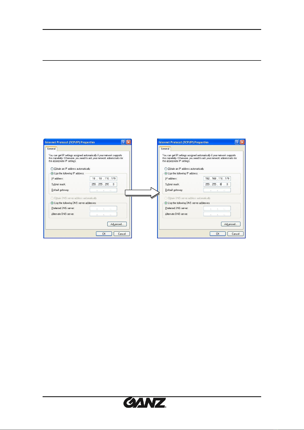
5.1. Set up network environment
The default IP address of your IP device is 192.168.XXX.XXX. You can find the available IP address
from the MAC address of your device. Please make sure the device and your PC are on the same
network segment before running the installation. If the network segment between your PC and
the device is different, change your PC’s settings as below.
IP address : 192.168.xxx.xxx
Subnet mask: 255.255.0.0
5.2. View video on web page
View the live video on a web page using your IP device and its IP address. You can use the
IPAdminTool or enter the IP address on the web page.
5.2.1. View video using IPAdmin Tool
IPAdminTool automatically searches all activated network encoders and IP cameras and shows
the product name, IP address, MAC address and etc.

PixelPro GXi Series ZS1-4DB1 Installation Guide
10-2013-A 12
To use the IPAdminTool and view the live video on a web page:
1. Start IPAdminTool. Names and info of currently activated devices appear as a list.
2. Right-click on the desired device and select Web view.
3. Click pop-up blocked and install the ActiveX setup.exe by clicking the Run or Save
button. You need to install the ActiveX for displaying the images.
4. Follow the instructions of the dialog boxes and complete the installation. Then the live
video is displayed on the main page of the web browser.
5. If the live video is not displayed with the message said, “This software requires the
Microsoft XML Parser V6 or higher. Please download MSXML6 from the Microsoft
website to continue. Error code: Can not create XMLDOMDocument.”, please download
and install the relevant MSXML.
Note
i
If the ActiveX setup.exe file fails to be installed successfully, close all of the
Internet Explorer windows and go to Program Files > AxInstall folder on your
computer. Then, run Uninstall.exe and try to perform the steps 1 to 4 above
again.

PixelPro GXi Series ZS1-4DB1 Installation Guide
10-2013-A 13
5.2.2. View video using IP address
View the live video on a web page using your IP device and its IP address. To have the correct
IP address ready and use it on a web page:
1. Convert a MAC address to an IP address or check the IP address on the IPAdminTool. Refer to
Appendix (C): Hexadecimal-Decimal Conversion Table.
(The MAC address is attached on the side or bottom of the device.)
2. Open a web browser and enter the IP address of the device.
3. Click pop-up blocked and install the ActiveX setup.exe by clicking the Run or Save button.
You need to install the ActiveX for displaying the images.
4. Follow the instructions of the dialog boxes and complete the installation. Then the live video
is displayed on the main page of the web browser.
5.3. Reboot
1. While the device is in use, press and hold the Reset button.
2. Release the Reset button after 2 seconds.
3. Wait for the system to reboot.
5.4. Factory Default
Resetting the device back to the factory default will initialize all parameters including the IP
address back to the factory defaults. To reset to the factory default:
1. While the device is in use, press and hold the reset button for about 10 seconds.
(LED blinks when the device is restored to factory default status.)
2. Wait for the system to reboot.
Note
i
The factory default settings can be inferred as follows:
IP address: 192.168.xx.yy
Network mask: 255.255.0.0
Gateway: 192.168.0.1
User ID: root
Password: pass
MAC address = 00-1C-B8-01-23-45 →IP address = 192.168.35.69
Convert the last two sets of hexadecimal numbers to decimal numbers.

10-2013-A 14
APPENDIX (A): SPECIFICATIONS
Summary
Video
Input
4 channel
Output
-
Compression Format
H.264, MJPEG Selectable per Stream
Number of Streams
Dual Stream for each channel, Configurable
Resolution
D1, 4CIF, 2CIF, VGA, CIF, QCIF, QVGA
Compression FPS
25 / 30 fps@D1 (PAL/NTSC)
Deinterlacing
Support (DSP)
Motion Detection
Support (DSP)
Burnt-in Text (Digital)
Support (DSP)
Audio
Input/output
4 channel / 1 channel(Mixed out)
Compression Format
G.711(uLow)
Function
Digital Input/output
4 channel / 4 channel
RS-485
4 channel
RS-232
-
Network
10/100 Base-T
Power Over Ethernet
-
Protocol
QoS Layer 3 DiffServ, TCP/IP, UDP/IP, HTTP, HTTPS, RTSP,
RTCP, RTP/UDP, RTP/TCP, mDNS, UPnP™, SMTP, DHCP, DNS,
DynDNS, NTP, SNMPv1/v2c/v3(MIB-II), IGMP, ICMP, SSLv2/v3,
TLSv1
SD slot
-
Electrical Characteristics
Video Input
1Vp-p, 75Ω
Audio Input
Mic-in, 0.178Vp-p, 10KΩ
Audio Output
Lineout, 2.26Vp-p , 10KΩ
Sensor(D/I)
Max 50mA@5VDC
Alarm(D/O)
Max 50mA@24VDC
On-state resistance: 50 Ω (max continuous)
Power Source
12VDC
Power Consumption
9W

PixelPro GXi Series ZS1-4DB1 Installation Guide
10-2013-A 15
Environment Condition
Operating Temperature
0˚C ~ 50˚C (32˚F ~ 122˚F)
Operating Humidity
Up to 85% RH
Mechanical Condition
Dimension
125(W) x 42(H) x 241(D) mm
Weight (Approx)
240g

PixelPro GXi Series ZS1-4DB1 Installation Guide
10-2013-A 16
APPENDIX (B): DIMENSIONS
(Unit: mm)

PixelPro GXi Series ZS1-4DB1 Installation Guide
10-2013-A 17
APPENDIX (C): HEXADECIMAL-DECIMAL
CONVERSION TABLE
Refer to the following table when you convert the MAC address of your device to IP address.
Hex
Dec
00
0
01
1
02
2
03
3
04
4
05
5
06
6
07
7
08
8
09
9
0A
10
0B
11
0C
12
0D
13
0E
14
0F
15
10
16
11
17
12
18
13
19
14
20
15
21
16
22
17
23
18
24
19
25
1A
26
1B
27
1C
28
1D
29
1E
30
1F
31
20
32
21
33
22
34
23
35
24
36
Hex
Dec
25
37
26
38
27
39
28
40
29
41
2A
42
2B
43
2C
44
2D
45
2E
46
2F
47
30
48
31
49
32
50
33
51
34
52
35
53
36
54
37
55
38
56
39
57
3A
58
3B
59
3C
60
3D
61
3E
62
3F
63
40
64
41
65
42
66
43
67
44
68
45
69
46
70
47
71
48
72
49
73
Hex
Dec
4A
74
4B
75
4C
76
4D
77
4E
78
4F
79
50
80
51
81
52
82
53
83
54
84
55
85
56
86
57
87
58
88
59
89
5A
90
5B
91
5C
92
5D
93
5E
94
5F
95
60
96
61
97
62
98
63
99
64
100
65
101
66
102
67
103
68
104
69
105
6A
106
6B
107
6C
108
6D
109
6E
110
Hex
Dec
6F
111
70
112
71
113
72
114
73
115
74
116
75
117
76
118
77
119
78
120
79
121
7A
122
7B
123
7C
124
7D
125
7E
126
7F
127
80
128
81
129
82
130
83
131
84
132
85
133
86
134
87
135
88
136
89
137
8A
138
8B
139
8C
140
8D
141
8E
142
8F
143
90
144
91
145
92
146
93
147
Hex
Dec
94
148
95
149
96
150
97
151
98
152
99
153
9A
154
9B
155
9C
156
9D
157
9E
158
9F
159
A0
160
A1
161
A2
162
A3
163
A4
164
A5
165
A6
166
A7
167
A8
168
A9
169
AA
170
AB
171
AC
172
AD
173
AE
174
AF
175
B0
176
B1
177
B2
178
B3
179
B4
180
B5
181
B6
182
B7
183
B8
184
Hex
Dec
DE
222
DF
223
E0
224
E1
225
E2
226
E3
227
E4
228
E5
229
E6
230
E7
231
E8
232
E9
233
EA
234
EB
235
EC
236
ED
237
EE
238
EF
239
F0
240
F1
241
F2
242
F3
243
F4
244
F5
245
F6
246
F7
247
F8
248
F9
249
FA
250
FB
251
FC
252
FD
253
FE
254
FF
255
Hex
Dec
B9
185
BA
186
BB
187
BC
188
BD
189
BE
190
BF
191
C0
192
C1
193
C2
194
C3
195
C4
196
C5
197
C6
198
C7
199
C8
200
C9
201
CA
202
CB
203
CC
204
CD
205
CE
206
CF
207
D0
208
D1
209
D2
210
D3
211
D4
212
D5
213
D6
214
D7
215
D8
216
D9
217
DA
218
DB
219
DC
220
DD
221

PixelPro GXi Series ZS1-4DB1 Installation Guide
10-2013-A 18
REVISION HISTORY
MAN#
DATE(M/D/Y)
Comments
11-2013-A
11/12/2013
Created.
03-2014-A
03/26/2013
Minor modification
09-2014-A
09/04/2013
Correct explanation for VCA license
Other manuals for PixelPro GXi Series
4
This manual suits for next models
1
Table of contents
Other Ganz Media Converter manuals

Ganz
Ganz ZA-NVE12K series User manual
Ganz
Ganz PixelPro GXi Series User manual

Ganz
Ganz ZN-S1000V User manual

Ganz
Ganz ZN-S100AE User manual

Ganz
Ganz ZN-S1000VE User manual

Ganz
Ganz ZP-EPC10 User manual

Ganz
Ganz ZA-NVE40K User manual
Ganz
Ganz PixelPro ZS1-4DS User manual

Ganz
Ganz ZN-S100V User manual
Ganz
Ganz PixelPro GXi Series User manual


