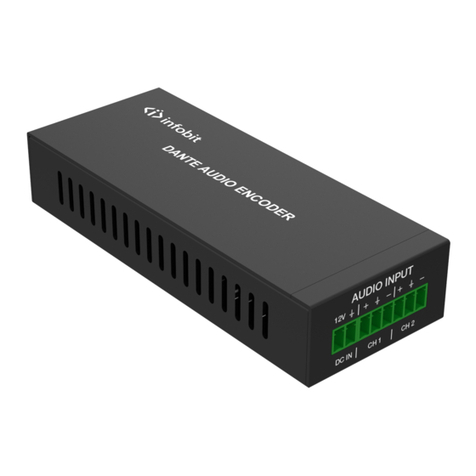
Ganz ZN-S100AE User manual


Table of Contents
1. Introduction.......................................................................................................................................4
2. Product Description ..........................................................................................................................5
2.1. Specifications............................................................................................................................ 5
2.2. Functions ..................................................................................................................................6
2.2.1. Front Panel.....................................................................................................................6
2.2.2. Rear Panel......................................................................................................................8
2.3. Serial Number / MAC Address...............................................................................................13
3. Installation....................................................................................................................................... 14
3.1. Basic Connections ..................................................................................................................14
3.2. Package Contents.................................................................................................................... 15
3.3. Installation Example ............................................................................................................... 16
4. Operation Description ....................................................................................................................17
4.1. Factory Default Settings .........................................................................................................17
4.2. Rebooting................................................................................................................................ 17
5. Power over Ethernet (PoE) ............................................................................................................ 18
5.1. Features...................................................................................................................................18
5.2. Mechanical characteristics......................................................................................................18
5.3. PoE compatibility ...................................................................................................................19
5.4. Power classfication .................................................................................................................20
6. Electrical characteristics ................................................................................................................21
6.1. Operating conditions...............................................................................................................21
6.2. Power consumption ................................................................................................................ 21

SafetyPrecautions
Users are strongly advised to adhere to directions and recommendations offered in this
manual. Failure to do so may result in problems during operation.
•Make sure the correct voltage is being supplied before turning the power ON.
•Do not install with the power turned ON. Doing so may cause an electric shock.
•Do not install in a very humid environment. Doing so may cause an electric shock.
•Do not install in an area exposed to sun light or heat. Doing so may cause deformation or
damage.
•Do not remove the product cover. Doing so may expose you to a hazard like electric shock.
•Do not use in areas containing inflammable materials like propane gas and gasoline or in areas
that generate dust. Doing so may cause an explosion or fire.
•Do not dismantle, repair or modify the product. Doing so may cause damage or an electric
shock. Refer all servicing to qualified personnel.
•Do not use water, thinner or organic solvent for cleaning the product exterior. Doing so may
cause damage or an electric shock. Use a dry cloth instead and turn OFF the power before
cleaning.

GANZ MPEG-4 Encoder Series Hardware Manual
2010/2-1 O 4
1.Introduction
ZN-S100AE, ZN-S1000AE, ZN-S2000AE and ZN-S4000AE compress video/audio data and transmit
the compressed video/audio data through the network in real time. GANZ encoder provides a high
quality video image with a limited bandwidth and storage capacity. These products are ideally suited
for a wide range of surveillance and remote monitoring applications. Main features are highlighted
below.
Main features
•High Quality Compression in real time streaming
•GANZ encoder provides high quality MPEG-4 and MJPEG encoding at D1 in real time.
Network
•RTP/RTSP and unicast/multicast are supported.
Streaming
•ZN-S2000AE and ZN-S4000AE support dual streaming mode such as different
codec/resolution/bit rate and so on.
•GANZ encoder supports de-interlacing by hardware.
Video/Audio
•Loop out is supported (ZN-S4000AE requires a T-BNC connector).
•ZN-S4000AE supports quad view in external monitor.
•GANZ encoder supports two ways audio (ZN-S100AE supports only audio input)
Transmits to client - G.711 by software
Receives from client - one digital audio
Additional Features
•RS-485 serial port for Pan/Tilt/Zoom. (Except ZN-S100AE)
•RS-232C serial port for some devices like a POS terminal. (Except ZN-S100AE)
•Motion detection by hardware.
•On Screen Display (OSD) by hardware.
SDK
•Three types (RTSP, UDA5,and HTTP-API) are provided for application development.

GANZ MPEG-4 Encoder Series Hardware Manual
2010/2-1 O 5
2.ProductDescription
2.1.Specifications
GANZ encoder series specification is shown as following Table 1.
ZN-S100AE ZN-S1000AE ZN-S2000AE ZN-S4000AE
2ch MPEG-4
50/60fps@D1
4ch MPEG-4
100/120fps@D1
1ch MPEG-4
25/30fps@D1
1ch MPEG-4
25/30fps@D1
Single
Mode
Dual
Mode
Single
Mode
Dual
Mode
Input channel 1ch 1ch 2ch 1ch 4ch 2ch
Output Channel - 1 Loop Out - 1 Loop
Out
1 Quad 2 Loop
Out
Compression MPEG-4, MJPEG Selectable per Channel
Resolution D1, 2CIF, CIF, QCIF
Video
Compression FPS 25/30fps@D1 25/30fps@D1 50/60fps@D1 100/120fps@D1
Input/Output
Channel
1/- ch 1/1ch 2/1ch 1/1ch 4/1ch 2/1ch
Audio(O
ptional)
Data Format PCM(software compression : G.711, uLaw)
Network 10/100 Base-T
DI/DO 2/2 2/2 4/4
RS-232C - Supported
RS-485 - Supported
Power over Ethernet Optional
De-interlacing Supported by hardware
Motion Detection Supported by hardware
OSD Supported by hardware
Video Stream Encryption AES
Protocols SNTP, DHCP, UDP, TCP, RTP, RTSP(unicast/ multicast)
Table 1. Specification for ZN-S1000AE, 2000 and 4000

GANZ MPEG-4 Encoder Series Hardware Manual
2010/2-1 O 6
2.2.Functions
2.2.1.FrontPanel
Figure 1. Front Panel of ZN-S4000AE
①, ②Indicator LED (Status, Network)
Status (Orange) and Network (Green) indicators display the following system information:
Status (Orange) Network (Green)
Power OFF OFF OFF
Booting in progress ON OFF
Successful network connection ON Blinking
Failed network connection ON OFF
Data transmission in progress Blinking(Slow) Blinking (Fast)
Table 2. Status of the GANZ encoder series indicator LED
1. System initialization and booting
When power is supplied to ZN-S4000AE, it is initialized for approximately 1 second. During this
time, the orange Status LED is turned on. After completion of booting, for a successful network
connection, the green Network LED blinks indicating that data is being transmitted. If network
connection fails, please check the LAN cable is connected or restart GANZ encoder.
2. Video streaming service
When an application runs, the Status LED blinks each second. The Network LED blinks at a rate
proportional to the amount of data being transmitted.
③, ④, ⑧Video Input BNC Connector (Vin 1, Vin 2, Vin 3 and Vin 4)
It is mainly used for video inputs, however it can be used for video loop-out some case as following
Table 3.

GANZ MPEG-4 Encoder Series Hardware Manual
2010/2-1 O 7
Single Stream Dual StreamModel
Video Input Video Loop-out Video Input Video Loop-out
ZN-S100AE Vin1 - - -
ZN-S1000AE Vin1 Video Loop-out - -
ZN-S2000AE Vin1, Vin2 T-BNC Connector Vin1 Vin2
ZN-S4000AE Vin1, Vin2,
Vin4
T-BNC Connector Vin1, Vin3 Vin2, Vin4
Table 3. Video Connector Usage
Termination Resistor DIP Switch may be applied, when Video Input BNC Connector is
used for video loop-out.
T-BNC connector is not included in GANZ encoder package.
⑤Termination Resistor DIP Switch (75ΩON)
A switch to turn ON/OFF a 75termination resistor is provided for each video input. Factory default
setting is ON. If impedance is mismatched between video inputs and outputs that are connected
together, you need to turn this DIP switch on/off to match the impedance to 75.
⑥Video Output BNC Connector (Vout - Only ZN-S4000AE)
Vout is used for ZN-S4000AE to display quad, switching view in external monitor.
⑦Reset Switch (Reset)
Reset switch is used for restarting GANZ encoder or resetting GANZ encoder as Factory Default
(FD). Refer to ‘4.1. Factory Default Settings’ for detailed procedures.

GANZ MPEG-4 Encoder Series Hardware Manual
2010/2-1 O 8
2.2.2.RearPanel
Figure 2. Rear Panel of ZN-S4000AE
Figure 3. Rear Panel of ZN-S100AE
①, ⑨Audio Input Jack (Ain 1,2 and Ain 3,4)
ZN-S2000AE and ZN-S4000AE have mono audio input channels using stereo audio socket. Therefore,
a special cable is needed to connect audio devices. There are two kinds of cables. Stereo cable is a
stereo jack to 2 RCA connectors (for ZN-S2000AE/4000) and Mono cable is a mono jack to 1 RCA
connector (for ZN-S100AE and ZN-S1000AE).
ZN-S1000AE and ZN-S100AE
Figure 4. ZN-S1000AE Audio Input Connection
⑨⑩⑪
⑫
⑬

GANZ MPEG-4 Encoder Series Hardware Manual
2010/2-1 O 9
ZN-S2000AE
Figure 5. ZN-S2000AE Audio Input Connection
ZN-S4000AE
Figure 6. ZN-S4000AE Audio Input Connection
Please pay attention to electric characteristics during installation.
(Detailed instructions are being prepared.)
②Audio Output Jack (Aout)
GANZ encoder provides one mono audio by using the stereo socket. Even if a stereo speaker is
connected, the both side have the same sound (mono output).
GANZ encoder audio outputs very low-watt, therefore it requires amplifier speaker (Do not use
headphone /earphone directly)
Figure 7. GANZ encoder Audio Output Connection

GANZ MPEG-4 Encoder Series Hardware Manual
2010/2-1 O 10
③Digital Input (DI 1~4)
ZN-S1000AE/2000 use 6 port terminal block for 2 channel Digital Outputs. ZN-S4000AE uses 8 port
terminal block for 4 channel Digital Outputs as shown Figure 2. It can be connected either voltage
type sensor or relay type sensor as following Figure 8 and Figure 9.
Do not use voltage and relay type sensor together.
Figure 8. Voltage Type Digital Input Connection

GANZ MPEG-4 Encoder Series Hardware Manual
2010/2-1 O 11
Figure 9. Relay Type Digital Input Connection
Please pay attention to electric characteristics during installation.
(Detailed instructions are being prepared.)
④Digital Output (DO 1~4)
ZN-S1000AE/2000 use 6 port terminal block for 2 channel Digital Outputs. ZN-S4000AE uses 8 port
terminal block for 4 channel Digital Outputs as shown Figure 2. DO devices can be connected as
following Figure 10.
Figure 10. Digital Output Connection

GANZ MPEG-4 Encoder Series Hardware Manual
2010/2-1 O 12
Please pay attention to electric characteristics during installation.
(Detailed instructions are being prepared.)
⑤RS-232C Terminal Block (RS-232C)
RS-232C Terminal Block is used for some devices such as POS terminal block.
Figure 11. RS-232C Connection
⑥RS-485 Terminal Block (RS-485)
The RS-485 serial port consists of DATA+, DATA- and GND as following Figure 12.
Figure 12. RS-485 Connection
⑦, ⑩LAN Connector (Ethernet)
This is a RJ45 LAN connector for 10/100 Base-T Ethernet.
⑧, ⑪Power Adaptor Connector (DC 12V)
ZN-S4000AE needs a DC 12V 3A adapter for power supply, and ZN-S1000AE/2000 uses a DC 12V
1A adapter.
⑫Reset Switch (Reset)
Reset switch is used for restarting GANZ encoder or resetting GANZ encoder as Factory Default
(FD). Refer to ‘4.1. Factory Default Settings’ for detailed procedures.
⑬Video Input BNC Connector (Vin)
This connector is used for video input.

GANZ MPEG-4 Encoder Series Hardware Manual
2010/2-1 O 13
2.3.SerialNumber/MACAddress
Serial number and MAC address is attached on the bottom as shown in Figure 13.
Figure 13. Serial Number/ MAC Address
550012345 MAC 00-1C-B8-C0-14-B1
ZN-S4000AE P122404010000-10002
MAC Address
Serial Number

GANZ MPEG-4 Encoder Series Hardware Manual
2010/2-1 O 14
3.Installation
3.1.BasicConnections
Figure 14 and Figure 15 illustrate the basic connection of ZN-S4000AE.
Figure 14. Front Panel Connection

GANZ MPEG-4 Encoder Series Hardware Manual
2010/2-1 O 15
Figure 15. Rear Panel Connection
3.2.PackageContents
GANZ encoder Assembly
-1ea (ZN-S4000AE, ZN-S2000AE or ZN-S1000AE)
ZN-S100AE ZN-S1000AE ZN-S2000AE ZN-S4000AE
Audio Cable LAN Cable
- Only cable for audio input is provided
- Except ZN-S100AE and ZN-S1000AE
- Cross type 1m cable 1 ea
Terminal Block Plug Power Adapter
- Except ZN-S100AE - AC100 ~ AC 240V power cable is included
ZN-S4000AE uses a 12V 3A adaptor.
ZN-S100AE, ZN-S1000AE and ZN-S2000AE use a 12V 1A adaptor.
ZN-S4000AE uses 8 port x 2ea terminal blocks.
ZN-S1000AE and ZN-S2000AE use 6 port x 2ea terminal blocks.

GANZ MPEG-4 Encoder Series Hardware Manual
2010/2-1 O 16
3.3.InstallationExample
Figure 16. GANZ encoder series Application Example
Normal operation may not be possible if temperature or humidity exceed levels
recommended in the GANZ encoder specification. Problems may also occur in
wireless environments.

GANZ MPEG-4 Encoder Series Hardware Manual
2010/2-1 O 17
4.OperationDescription
4.1.FactoryDefaultSettings
Factory default settings are as follows:
•IP address: 192.168.xx.yy (refer to 2.3 Serial Number / MAC Address)
•Mask: 255.255.0.0
•Gateway: 192.168.0.1
•User ID: root
•Password: pass
MAC address = 00-1C-B8-C0-14-B1 IP address = 192.168.35.69
Factory Default (FD) initialization procedure is as follows:
Figure 17. Indicator LEDs and Reset Switch
1. Turn ON the power.
2. Press “Reset” button when Status LED starts blinking rapidly.
3. Release “Reset” button when Status LED blinks slowly. (About 5 seconds after booting)
4.2.Rebooting
Reset can be carried out as follows:
1. Press Reset for 1 second.
When Reset function is activated, Status LED and Network LED will blink together, twice. User
may stop pressing Reset at this point.
2. When “Reset” function has been completed, LEDs will stop blinking.
Convert the Hexadecimal number to Decimal number

GANZ MPEG-4 Encoder Series Hardware Manual
2010/2-1 O 18
5.PoweroverEthernet(PoE)
The PoE module used in GANZ encoder is commercially available module without modification. The
standard GANZ encoder does not include PoE module in it. PoE module is included on the request of
a customer. For the detailed information, please contact sales person.
The PoE module is designed to extract power from a conventional twisted pair Category 5 Ethernet
cable, conforming to the IEEE 802.3af Power-over-Ethernet (PoE) standard.
IEEE 802.3af allows for two power options for Category 5 cables and the PoE module have two pairs
of power inputs pins: - VA1&2 and VB1&2 to accommodate this.
The PoE module signature and control circuit provides the PoE compatibility signature and power
classification required by the Power Sourcing Equipment (PSE) before applying up to 15W power to
the port. The PoE module is compatible with Class 0 to Class 3 equipment.
The high efficiency DC/DC converter operates over a wide input voltage range and provides a
regulated low ripple and low noise output. The DC/DC converter also has built-in overload and short-
circuit output protection.
5.1.Features
•IEEE802.3af compliant
•Small SIL package size - 56mm (L) x 14mm (H)
•Overload and short-circuit protection
•1500V isolation (input to output)
5.2.Mechanicalcharacteristics
Dimension: 56mm (L) x 14mm (H)
Figure 18. Dimension of PoE module
The following pictures show PoE module installed in the products.

GANZ MPEG-4 Encoder Series Hardware Manual
2010/2-1 O 19
Figure 19. ZN-S1000AE without PoE module
Figure 20. ZN-S1000AE with PoE module installed
5.3.PoEcompatibility
With non Power Sourcing Equipment (PSE)
When it is connected with non PSE, the power adaptor should be connected.
With power adaptor
Connecting both PSE and power adaptor does not do any harm to the products. Disconnecting power
adaptor while it is operating does not stop operation. The product continues to work without rebooting.

GANZ MPEG-4 Encoder Series Hardware Manual
2010/2-1 O 20
5.4.Powerclassfication
The PoE Power Class supported by GANZ network camera/encoder is as following Table 4.
Model Power Class
ZN-D310AE
ZN-D(N)T3500AE
ZN-S100AE
ZN-S1000AE
ZN-S2000AE
ZN-S4000AE
0
Table 4. Power Class supported by GANZ network camera/encoder
Table 5 shows IEEE 802.3af power classes.
Class Usage Minimum Power Levels
Output at the PSE
Maximum Power Levels at the
Powered Device
0 Default 15.4W 0.44 to 12.95W
1 Optional 4.0W 0.44 to 3.84W
2 Optional 7.0W 3.84 to 6.49W
3 Optional 15.4W 6.49 to 12.95W
4 Reserved for Future Use Treat as Class 0 Reserved for Future Use
Table 5. IEEE 802.3af PSE and Powered Device Power Classifications
This manual suits for next models
3
Table of contents
Other Ganz Media Converter manuals

Ganz
Ganz ZN-S100V User manual

Ganz
Ganz ZP-EPC10 User manual
Ganz
Ganz PixelPro ZS1-4DS User manual

Ganz
Ganz ZA-NVE12K series User manual

Ganz
Ganz ZN-S1000V User manual
Ganz
Ganz PixelPro GXi Series User manual

Ganz
Ganz ZA-NVE40K User manual
Ganz
Ganz PixelPro GXi Series User manual

Ganz
Ganz ZN-S1000VE User manual
Ganz
Ganz PixelPro GXi Series User manual
