GAPOSA QC400 User manual

PANTONE 302C
RAL 5000
C 100
M 30
Y 0
K 50
PCB VERSION 7-0217 R1717
VERSION – SOFTWARE V05_00
QC400
Automatic control unit for three/single-phase motors
with digital or mechanical limits


3
DIRECTIVES
IMPORTANT SAFETY INSTRUCTIONS
These instructions contain important information on the installation and the use of the QC400 unit. Please keep them
even after installation. Do not start installing the QC400 unit without having first read these instructions. The installa-
tion can be made only by a qualified technician. In order to respect the rules in force, the installation must include an
automatic cut off switch with minimum distance between the contacts of at least 3mm. The safety of the control unit
depends on a correct installation. Be at a reasonable distance from shutter/awnings in movement. Check frequently if
any loss of balance, sign of wear or damages wires are shown. Do not use if any repairing or maintenance is needed.
GAPOSA declines all responsibility in case of improper use of the product or of an incorrect installation.
WARNING: it is very important for the people’s safety to follow strictly these instructions.
IMPORTANT: Stay at distance while the shutter is in movement.
IMPORTANT: Frequently check whether any cable disconnects, wears out or any damage happens. Do not use the con-
trol unit in case a reparation or a maintenance job is required.
KEEP THIS INSTRUCTIONS.
Warning: it is highly recommended to activate the impulsive mode only after having completed the set-up and
adjustments of the control unit. In particular, during the mechanical limit switches adjustment, select always the dead-
man operation mode. During the encoder limit switches set-up the control unit will only allow the dead-man working
mode.
DESCRIPTION
The QC400 has been designed to operate an industrial door safely under electrical control of a pushbutton or key switch.
Its intended use is to be connected to a suitable motor not exceeding the load for the controller.
Connections are provided for mains supply (both 3ph and 1ph), motor power, mechanical or electronic limits,
Push Buttons, Pneumatic or Electrical or Optical Safety Edge, Photo beam safety and 24VDC Auxiliary power (100mA
max). Optional plug-in connectors for Radio and Traffic light.
Basic functions include: - Stop, Open, Close, and Auto close via a time delay provided a suitable monitored safety edge is
fitted.
2014/35/UE 2014/30/CE 2014/53/CE 2006/42/CE
EN 61000-6-2:2005 EN 61000-6-3:2007 + A1:2011
EN 60950-1:2006 + A1:2010 + A2:2013 +A11:2009 + A12:2011
EN 13241-1:2004 + A1:2011 EN 13849-1:2015
EN 12453:2017 EN 12978:2003 + A1:2009
EN 301489-1:2008 EN 301489-3:2002
EN 300220-2:2007 EN 13241-1:2004 + A1:2011

4
Installation Vertical on a vibration free and flat wall
Temperature range (operating) -10…+50°C
Humidity Up to 93% RH non-condensing.
Vibration Low-vibration installation, wall mounted.
Supply voltage:
(Selectable by jumper
using terminal ‘X1’)
3ph - 230/400V~ ± 10% L1,L2,L3,PE (‘N’ required ONLY for services - see par. 7/9)
1~ 230V~ ± 10% L1,N,PE
50/60Hz, Mains fuse max: 3 x 10A
Transformer Max 10 VA , VDE 0570/EN61558
Secondary winding is overload protected by fuses.
Motor output Max motor load by 3 x 400VAC: 2.2 kW
Max motor load by 3 x 230VAC: 1.3 kW
Max motor load by 1 x 230VAC: 0.75 kW
Emergency stop, Stop and safety jumper. Function as normal stop command and disconnect power to contactor coil.
24VDC Output (terminals X6-8,9): 24VDC ± 20% (non-regulated), Max load: 100mA
Safety edge input:
(X5-3,4) PNE/air switch
Electric type - 8k2 termination ± 10%
Optical type (Fraba OSE or Dalmatic TSS/RSS)
Performance level C, Category 2
Optical safety edge:
(X5-5,6,7) Input voltage high (green): 2.5 - 5.0 Volt.
Input voltage low (green): <0.5 Volt.
Input frequency range (green): 250 – 2000 Hz. (50% duty-cycle)
Pulse interval maximum (green): 7.0 mS (when not 50% duty-cycle)
Photo input:
(X6-9,10,11,12) Photo, 24 VDC (e.g. self contain photo cell)
Performance level C, Category 2
Electronic limits RS485, Data+ Data-, terminated with 120 Ohm.
Designed for Dalmatic encoder, Feig encoder and Kostal encoder (self setting)
Mechanical limits Plug-in connector X7 for mechanical switches.
AUX solid-state relay output (X5-1,2): NO output. Max 30V – Max 50 mA.
Box dimension 305 x 210 x 120 mm
Reversetime (Photo, Open) = 0.50 sec.
Reversetime (safety edge) = 0.25/0.1/0.05 sec.
Auto close time (Factory setup15 sec.) = 1 – 240 sec. (adaptive)
Runtimer = 120 sec.
Electronic afterrun with monitoring (DIP4 = ON) = 0.3 sec.
Min. Pullbacktime by photo, edge and force reversing
(by DIP1 and DIP2 = OFF) = 0.1 sec.
Opening counts, service interval = 1000 counts
Reset time, Service LED (active elec. Counter) = 240 sec.
Time delay before position failure (encoder is not moving) = 4.0 sec.
Dw fail afterrun = 0.5 sec.
AUX 1 setting: ON when door is stopped.
Force control (DIP5 = ON) Force control set points = 4+4
Force control delay (before measuring) = 0.8 sec.
Force control frequency range = 60 – 240 Hz
(900 – 3600 RPM with 4 pulses/rotation)
Stop by force (DIP6=OFF/ON) = -2.5/-1.0 %
Wear limit (from initial values) (DIP6=OFF/ON) = 6/5%
Automatic update of set points (force control) =
0.3%/10 Door cycles
TECHNICAL DETAILS
SOFTWARE SETTINGS
1
2
3
4
5
6
7
8
9
10
11
12
13
14
15
U
V
W
U
V
MW
SAFETY
JUMPER
X5
X4
X1
X2
X8
X6
S3
S1
X7
X10
X9
X3
12 11 10 9 8 7 6 5 4 3 2 1
PLUG-IN RADIO
RECEIVER
QCMR500
ATTENTION!
In case of MECHANICAL
LIMIT SWITCHES
terminals 2 and 5 of the
connector X6 must be
jumped
OPEN
CLOSE
OPTICAL EDGE
BR.
GR.
WH.
PNE/8K2
EDGE
AUX1 NO
MAX 30V
MAX 50mA
STOP
GO
FUNC.
E.STOP
+
-
24 V
OUTPUT
SAFETY PHOTO
COM OL CL
N
SPEED
N
PULSE
SAFETY
CHAIN
+12V
GRD
ENCODER
DATA+
DATA-
PHOTO
+24V
ENCODER FOR
ELECTRONIC
LIMITS
+12V
GROUND
DATA +
DATA -
SAFETY
PULSE
12/24V
12/24V
NA / NC
0V
0V
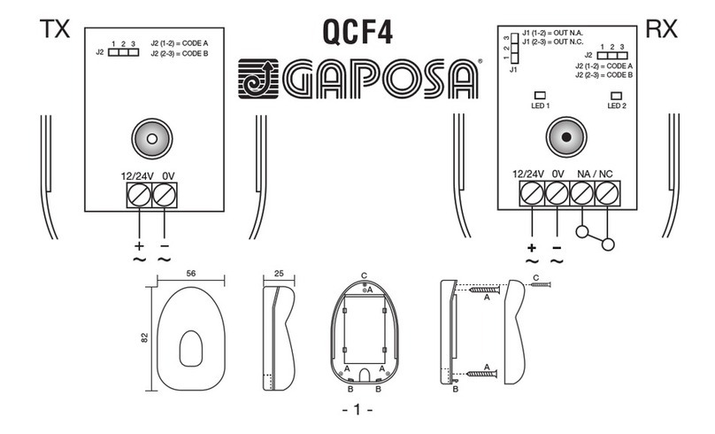
QCF4
PHOTOCELL
TX RX
OPEN BUTTON
MECHANICAL
LIMIT SWITCHES
CLOSE
LIMIT
OPEN
LIMIT
CL
OL
COM
S4
STOP BUTTON
CLOSE BUTTON S2
OPTION SWITCH
CONN.
BROWN
GREEN
WHITE
QCLSM
PLUG-IN
TRAFFIC LIGHT
OPEN
CLOSE
PUSHBUTTON
BOX
PNE
8k2
YOU MUST
CONNECT ONLY
ONE SAFETY
EDGE TYPE
!
EMERGENCY
STOP
STOP
GO FUNCTION
U
PE
PE
PE
PE
3 PHASE
230/400VAC
MAINS POWER
1 PHASE
230VAC
MAINS CEE PLUG
PE NL3 L2 L1
L1 L3L2(N)
L1
V
MW
ATTENTION!
MAINS VOLTAGE SELECT.
WRONG JUMPER PLACEMENT
CAN DESTROY THE CONTROL
VOLTAGE SELECT
230V~ 400V~
MAINS SUPPLY MAX 10mA
SETUP
PROGRAM
MEMBRANE KEYPAD
1~ 230Vac
U=OPEN
V=COMMON
W=CLOSE
3~ 230/400Vac
NOTE: PE must be connected first
and disconnected last if motor plug in terminals
are disconnected
1
2
3
4
5
6
7
8
9
10
ON DIP
AUX 1
SOLID STATE RELAY
SIGNAL OUTPUT
BROWN
GREEN
WHITE
QCSE OPTICAL
SAFETY EDGE
X16
!
5

6
1 INSTALLATION
For a correct installation:
•Install where the control unit can be protected from rain or adverse weather conditions
•Mounting must be vertical
•The mounting surface must be flat and not be subject to vibrations
•Do not install in an area of potential risk of condensation
•It is important that the door can be clearly seen from the position of the control while operating
•Install in an area not accessible to children or unauthorized persons
•Do not perform any electrical connections before the installation is completely accomplished
2 ELECTRICAL OPERATING INSTRUCTIONS
Read carefully and respect the connection’s sequence. IMPORTANT! All the connection operations must be performed
only after the main power supply has been disconnected. TURN OFF THE MAIN POWER SWITCH BEFORE ANY OTHER
OPERATION!
When connecting control to mains supply a mains isolator switch (16A CEE - plug) according EN 12453 is required.
The supply disconnect device (main switch or CEE plug) must be installed between 0.6 m and 1.7 m above floor level.
2.1 CONTROL UNIT POWER SUPPLY
The control unit can be powered in tree different modes: 400V~ 3-phase, 230~ 3-phase or 230V~ 1-phase.
WARNING! The installation must include an automatic cut off switch with minimum distance between the contacts of at
least 3 mm.
WARNING: The power supply of the motor and of the control unit must be the same. Otherwise you can damage the mo-
tor and the control unit and put at risk the safety of the installer.
If you need to disconnect the power cable and then to reconnect it or change the control unit wiring sequence, you HAVE TO
connect the wires properly, restoring the original configuration. Take care to connect the ground wire to the X3 terminal.
WARNING! Verify the direction of rotation of the motor supplied with 3ph x 400V or 1ph x 230V: pay attention to the direc-
tion of rotation of the motor: by pressing the OPEN button (S1) the door has to open while, by pressing the CLOSE button
(S2), the door must close. In case of wrong direction, reverse two of the phases (L1, L2 and L3) on the X2 terminal or U
(OPEN) and W (CLOSE) on X4 terminal.
2.2 CONNECTING THE CONTROL UNIT TO THE MOTOR
After the motor and control are fitted they can be connected with a plug-in cable.
The cable has plugs on each end for an
easy fitting.
The plugs for motor and control panel are
different and cannot be interchanged.
VOLTAGE
SELECT
X3 PE
1 PHASE
230VAC
MAINS
CEE PLUG
PE
N
L1
L3
L2(N)
L1
X3 PE
3 PHASE
400VAC
MAINS
CEE PLUG
PE
L2
L1
L3
L2(N)
L1
L3
WRONG JUMPER
PLACEMENT
CAN DESTROY
THE CONTROL
X1
X2
VOLTAGE
SELECT
X1
X2
X3 PE
3 PHASE
230VAC
MAINS
CEE PLUG
PE
L2
L1
L3
L2(N)
L1
L3
WRONG JUMPER
PLACEMENT
CAN DESTROY
THE CONTROL
VOLTAGE
SELECT
X1
X2
WRONG JUMPER
PLACEMENT
CAN DESTROY
THE CONTROL
1x230VAC (L1, N, PE) 3x400VAC (L1, L2, L3, PE)3x230VAC (L1, L2, L3, PE)
N required ONLY for services - see par. 7/9
U
V
W
U
V
MW
SAFETY
JUMPER
X4 X3
U
PE
PE
PE
V
W
1 phase
230V Motor
U = OPEN
V = COMMON
W = CLOSE
3~ 230V
3~ 400V
Motor
NOTE: PE must be connected first and disconnected last
if motor plug-in terminals are disconnected
M

7
3 DIPSWITCH FUNCTIONS
1 2 3 4 5 6 7 8 9 10
DIP
ON S3
OFF
NOTE OPERATING LOGIC DIP
12345678910
ADead-man OPEN/CLOSE OFF OFF - - - - - - - -
BImpulse OPEN/CLOSE ON ON - - - - - - - -
CImpulse OPEN / Deadman CLOSE ON OFF - - - - - - - -
OPTIONS
DAuto close (after delay time) ON ON ON - - - - - - -
EElectronic after run / edge monitoring ---ON------
FForce control (Multiturn)
(NOT AVAILABLE AT THE MOMENT) ----ON-----
Force control fine sense
(NOT AVAILABLE AT THE MOMENT) -----ON----
GGo Function Standard - ON - - - - OFF - - -
Go Function Special (Start/Stop, radio) - ON - - - - ON - - -
Edge super fast reverse 0.05 sec
(NOT AVAILABLE AT THE MOMENT) -------ON--
Edge reverse time – Normal
(NOT AVAILABLE AT THE MOMENT) - - - - - - - OFF ON -
LIMIT SWITCH TYPE SELECTION
Mechanical limit switch ---------OFF
Electronic encoded limit switch ---------ON
NOTE SAFETY LOGIC
AWhen an obstacle is detected during the DOWN operation the movement is stopped with a brief upward movement; It has no effect on the way UP.
BWhen an obstacle is detected during the UP operation It has no effect. During the DOWN operation the movement is reversed until the opening
limit switch.
CWhen an obstacle is detected during the UP operation It has no effect. During the DOWN operation the movement is reversed until the opening
limit switch
D
This function can only be selected when DIP2 is in ON position and safeties are connected. The auto closing time is preset to 15 Sec. To reset
a new time setting, run the door to open position and push both open and close buttons for minimum 5 Sec. When the red LED START flashing,
release the buttons. After that wait until the new desired auto closing time and then push the close button. Max auto closing time is about 4 min.
If max setting time is exceeded, the red LED STOP flashing and the auto close time is adjusted back to 15 Sec. Auto closing time is remembered
after power OFF. Auto closing can also be disabled with a switch connected to X16 connector.
EWhen DIP4 is in ON position, the edge monitoring is selected. When adjusting the limits, DIP4 is set to OFF. Close limit switch shall be adjusted
such as the door is stopped 5 cm before the floor. After this change DIP4 to ON. (PNE edge only). Clearing fail is done by closing the door in dead-
man mode (hold to run mode), keeping the close push-button ON until the door is stopped by signal from safety device.
F
Force control setting: Change DIP5 to ON position. (Fail LED and LED on membrane keypad showing long flash). The door shall be mounted and
limits adjusted before activating the force control. With DIP5=ON the force control is automatic learned by the first 2 fully open cycles without
stop, starting in closed position. The controller will work as a dead-man controller until all force values are learned. If the control only run by
small step when closing – Tacho pulses is missing.
GSpecial technical information - see par. 10
ADDITIONAL FEATURES
Photo Photo circuit is tested before every close operation. Photo circuit must be connected during the setting process.
Service Service showing for every 1000 openings (see separate LED guidance). Reset of service is done by activating the electronic counter and keeping
this active for minimum 4 minutes. The controller will then automatic switch to normal operation with service LED out. The service function is
only activating the service LED. (NOT AVAILABLE AT THE MOMENT)
Safety The door cannot close when there is an error in the photo or safety edge. By a special code the door can close one time in hold to run mode.
Press and hold STOP when pressing 222111 (2 = DOWN push button and 1 = OP push button). Code must be pressed within 6 sec

8
4 CONNECT QC400 TO MECHANICAL LIMIT SWITCH MOTOR
ATTENTION: if you connect a control unit already pre-set for mechanical limits to a motor with encoder limits, the motor
won’t work correctly. In particular, the motor will not find the limit positions and this could put at risk the safety of peo-
ple and/or things.
In order to connect the QC400 with a motor with mechanical limits set the DIP10 on S3 in OFF (See 4.1 PROGRAMMING).
1GREY > OPEN LIMIT SWITCH
2GREEN > OPEN BUTTON (Micro on motor limit switch)
3WHITE > SAFETY
4YELLOW > CLOSE BUTTON (Micro on motor limit switch)
5PINK > CLOSE LIMIT SWITCH
6BROWN > SAFETY
1
2
3
4
5
6
7
8
9
10
11
12
13
14
15
X5
X7
X6
12 11 10 9 8 7 6 5 4 3 2 1
GRD
ATTENTION!
In case of mechanical
limits terminals 2 and 5
of the X6 must
be jumped
!
ATTENTION!
Never bridge
the 14-15 terminals
because safeties
will be disable
!
123
4 5 6
FLCE31W012

9
4.1 PROGRAMMING WITH MECHANICAL LIMIT SWITCH
ATTENTION: to let the safeties work, these must be connected before starting the control unit setup.
Setup process - Mechanical limits standard
1
Set DIP10 in OFF position for selecting mechanical limits and DIP1 and DIP2 to OFF position for deadman operation.
Standard control for mechanical limits are for PNE edge type (3-4 terminals on X5) and no photo connected.
ATTENTION: Switching DIP10 to ON position and back to OFF will reset to mechanical standard with ONLY PNE edge
type.
2Press OPEN or CLOSE to the desired close and open limit position and adjust cam until the limit is correct.
Note: if door is moving in the wrong direction the 2 phases on the mains connection must be interchanged.
3Limits are now adjusted.
Check that the safety edge is working (if mounted).
Setting process - Mechanical limits with other safety connected
ATTENTION: additional safeties as OSE (connected to X5 5-6-7) or photocell (connected to X6 9-10-11-12)
will be active only after the setting process
4Make setup process 1 and 2 and move the door away from close limit.
5Connect the requested safeties.
Activate setting by pressing OPEN+STOP for about 10 sec then release. The red LED FAIL (PCB) start with 2 short flashes
6Press STOP to stop setting the edge type and photo. Yellow LED SPEED/SER confirming with 1 sec
7
Limits are now adjusted and edge type and photo circuit are memorised. Check that the safety functions are working as
expected.
ATTENTION: moving DIP10 to ON position and back to OFF will reset to mechanical standard with ONLY PNE edge type.
Yellow LED CONF./SER. (PCB)
Fixed light Service needed (open
counts reached)
1 sec. flash Confirming learning
process
Green LED POWER (PCB)
Fixed light The controller is powered
Red LED CIRCUIT ERROR (PCB)
Fixed light PCB circuit error fail
Red LED FAIL (PCB)
Fixed light
If Photo or Edge is activated
when CLOSE pushbutton is
activated
1 long flash Auto close learning active
2 short flashes Limits, edge and photo not
learned
2 long flashes Force control (speed) not
learned
3 long flashes Door stopped by force control
4 long flashes Door stopped by runtime
5 long flashes Door stopped by force control
wear
6 long flashes Tacho failure – pulses missing
Continues long
flashes
Fail state PNE edge monito-
ring. Check impuls by floor
missing.
Yellow LED STOP (PCB)
Fixed light Stop activated or both limits
are active
1 long flash Safety chain activated
2 long flashes Photo – safety test failed.
3 long flashes Safety edge – safety test
failed.
4 long flashes Stop circuit – safety test
failed.
5 long flashes Safety chain – safety test
failed
6 long flashes
EEPROM failure. Elec.
Counter or position counter by
force control
7 long flashes EEPROM failure. Powerup
failure
8 long flashes Welded contactor fail
9 long flashes Internal watchdog timeout.
10 long flashes Main processor crystal fail
4.2 LED GUIDANCE

10
5 QC400 CONNECT TO ELECTRONIC LIMIT SWITCHES MOTOR
ATTENTION: if you connect a control unit already pre-set for mechanical limits to a motor with encoder limits, the motor
won’t work correctly. In particular, the motor will not find the limit positions and this could put at risk the safety of peo-
ple and/or things.
In order to connect the QC400 with a motor with electronic limit switch:
1. Remove the 3pins white terminal from the cable (our part # FLCE31W012 ) - Fig. 1
2. Peel the 3 wires and connect them as showed in FIG. 2
3. See 5.1 PROGRAMMING
1 2 3
4 5 6
X6
12 11 10 9 8 7 6 5 4 3 2 1
1 2 3
4 5 6
1
2
3
4
5
6
7
8
9
10
11
12
13
14
15
X5
ATTENTION!
The 14-15 terminals
must be jumped
!
FIG. 1 FIG. 2
1GREY > GND
2GREEN > DATA -
3WHITE > GND
4YELLOW > DATA +
5PINK > SAFETY
6BROWN > +12V

11
Setting process
1Turn OFF the power and connect the encoder and all safety equipment.
The controller memorises the encoder type by power-up.
2
Set DIP10 in ON position and turn the power ON. Activate setting by pressing OPEN + STOP for about 10 sec until the
red LED FAIL (PCB) starts with 2 short flashes
ATTENTION: Switching DIP10 to ON position and back to OFF will reset to mechanical standard with ONLY PNE edge
type.
3
First press the CLOSE button to the desired down limit position.
Note: if door is moving in the wrong direction the 2 phases on the mains connection must be interchanged.
(Alternatively choose the special phases interchange function by pressing OPEN + STOP for 20 sec. - Yellow LED SPE-
ED/SER confirming with 1 sec.)
4Press STOP to set the down limit position. Yellow LED SPEED/SER confirming with 1 sec
5
Press OPEN to the desired UP limit position.
By open position you can adjust the UP limit position finely by running OPEN and CLOSE, but first operation must be in
OPEN direction for minimum 2 sec.
6Press STOP button to save the UP limit position, encoder direction, edge type and photo
Yellow LED SPEED/SER confirming with 1 sec
7Limits are now adjusted and edge type and photo circuit are set.
Check that the safety edge and photo functions are working as expected.
Yellow LED CONF./SER. (PCB)
Fixed light Service needed (open
counts reached)
1 sec. flash Confirming setting process
Green LED POWER (PCB)
Fixed light The controller is powed
Red LED CIRCUIT ERROR (PCB)
Fixed light PCB circuit error fail
Red LED FAIL (PCB)
Fixed light
If Photo or Edge is activated
when CLOSE pushbutton is
activated
1 short flashes No answer from encoder.
Check RS485
1 long flash Auto close setting active
2 short flashes Limits, edge and photo not
learned
2 long flashes Force control (speed) not
learned
3 long flashes Door stopped by force control
4 short flashes Calculation failure (e.g. both
limits the same)
4 long flashes Door stopped by runtime
5 long flashes Door stopped by force control
wear
6 long flashes Tacho failure – pulses missing
7 short flashes
Encoder position out of learned
area. (Reset by power up or
resetting)
8 short flashes Kostal encoder – Power
failure.
Continues long
flashes
Fail state PNE edge monito-
ring. Check impuls by floor
missing.
Yellow LED STOP (PCB)
Fixed light Stop activated or both limits
are active
1 long flash Safety chain activated
2 long flashes Photo – safety test failed.
3 long flashes Safety edge – safety test failed.
4 long flashes Stop circuit – safety test failed.
5 long flashes Safety chain – safety test failed
6 long flashes
EEPROM failure. Elec. Counter
or position counter by force
control
7 long flashes EEPROM failure. Powerup
failure
8 long flashes Welded contactor fail
9 long flashes Internal watchdog timeout.
10 long flashes Main processor crystal fail
5.2 LED GUIDANCE
5.1 PROGRAMMING WITH ELECTRONIC LIMIT SWITCH
ATTENTION: to let the safeties work, these must be connected before starting the control unit setup.

12
6 BRAKE RELAY CONNECTIONS ON AUX 1
Brake can be used for both mechanical and electronic limits.
AUX1 output is going OFF 30 ms
before motor contactor is turned
ON for releasing the brake a
brief time before motor starts.
AUX1 output is going ON 20 ms
before motor contactor is turned
OFF, for activating the brake a
brief time before motor stops.
7 FLASHING LIGHT CONNECTIONS (only for 3phase power supply)
1
2
3
4
5
6
7
8
9
10
11
12
13
14
15
X5
X6
12 11 10 9 8 7 6 5 4 3 2 1
External Relay
ON when motor is OFF Brake
rectifier
24VDC
Max 50 mA M
AC
DC
L N
Alternative
-
(negative)
connection
+
-
24 V
OUTPUT
AUX1 NO
MAX 30V
MAX 50mA
N
Neutral of
the power
supply
230Vac with
autolamping
U
V
W
X4

13
8 PLUG-IN RADIO RECEIVER QCMR500 (OPTIONAL)
The control can be radio operated thanks to the QCTE transmitter that allows the storage of 1997 radio codes.
The QCTE transmitter must be matched to the QCMR500 radio receiver, already inserted into the related slot (see page 5).
Set DIP7 in ON (GO Special functions - see par. 10).
Please look at the QCMR500 instructions to connect it to the control unit and to match it to the transmitter.
Radio plug-in terminals:
Pin 1 = output signal to board “Go function” (+24V)
Pin 2 = connected to board +24V after stop circuits
Pin 3 = Not connected.
Pin 4 = connected to board +24V after stop circuits
Pin 5 = connected to GND on board. (supply)
Pin 6 = connected to +24 power on board (supply)
Pin 7 – 10 = Not connected.
NOTE: the entrance “GO” (terminals 11-12 on X5) follows the
same logical of functioning selected for radio receiver.
9 PLUG-IN TRAFFIC LIGHT QCLSM (OPTIONAL)
This is a plug-in board to be used with the QC400 in order to control flashing lights, courtesy lamps or traffic lights during
the operation of the door or shutter.
Connect the QCLSM to X10. The possible operation options are described in the QCLSM instruction manual.
RED
LIGHT
POWER
SUPPLY
230V~
GREEN
LIGHT
MOLEX CONNECTOR
1 2 3 4 5 6 7 8 9 10
ON
DIP
12 11 10 9 8 7 6 5 4 3 2 1
1
2
3
4
5
6
7
8
9
10
11
12
13
14
15
PLUG-IN RADIO
RECEIVER
QCMR500

14
10 SPECIAL TECHNICAL INFORMATION
Go Func normal: Go function input terminal X5-11,12. (DIP7 OFF)
Go function, when photo safety is connected to controller:
When Door is not open > the door will open.
When door is open > the door will start closing.
When door is running down > the door will open.
When door is running up > no change.
Go function, when no photo safety is connected to controller:
When Door is not open > the door will open.
When door is open > no closing (for safety reason because no photo)
When door is running down > the door will open.
When door is running up > no change.
Go Func special: Go function input terminal X5-11,12. (DIP7 ON)
Go function, when photo safety is connected to controller:
When Door is not open or closed> the door will do opposite of last.
When door is open > the door will start closing.
When door is running down > the door will stop and next push opening.
When door is running up > the door will stop and next push closing
Go function, when no photo safety is connected to controller:
The “go function special” is not active when no photo is connected. (safety)
Photo disabling before the door reaches the floor level
If you want to disable the photo safety function a little distance before close limit:
1. Move the door to the desired disabling point -
2. Activate the STOP button and then also the OPEN + CLOSE buttons for 5 sec. ( 3-double push)
3. Confirm LED will flash 1 sec.
Check that that the disabling point is correct.

15

0119
Gaposa srl - via Ete, 90 - 63900 Fermo - Italy
www.gaposa.com
Table of contents
Other GAPOSA Engine manuals
Popular Engine manuals by other brands

Beta Marine
Beta Marine Beta 10 Operator's maintenance manual

Peugeot Motorcycles
Peugeot Motorcycles FB-0-1-2-4 Workshop manual

Flux
Flux FBM 4000 Ex Original attachment

Montanari
Montanari MGV19 Use and maintenance

Husqvarna
Husqvarna DMS 160 A Operator's manual

Volvo Penta
Volvo Penta TAD1360VE Operator's manual

WEICHAI
WEICHAI BAUDOUIN PowerKit 16M33 Series Operation and maintenance manual

ABB
ABB AMD Rg 355 Installation, operation and maintenance instructions

Harbor Freight Tools
Harbor Freight Tools Predicator 212cc owner's manual

WEICHAI
WEICHAI WD615 Usage instructions

Perkins
Perkins XGB 1600 Series Operation and maintenance manual

GEIGER
GEIGER GEIGER-MODULARline operating instructions