Pull the Tractor Scoot to make sure the Handle
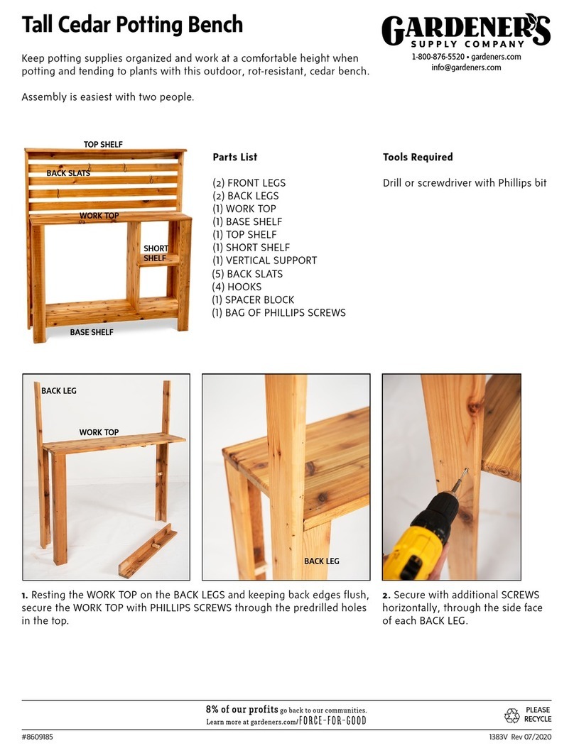
moves freely left and right. If the handle does not
steer well or the pivot seems stiff, you may need to
slightly loosen one or both of the nuts on the Axle.
When extended, twist the Handle to Lock it into
place.
Step 7. Using the small 6x15 mm Bolts,
nuts and washers, attach the Tray (front first) to the
Frame using the Small Reinforcing Plate. Place the
Plate under the front rim of the Tray lining up the
holes with the predrilled holes in the (pre-welded)
front Tray Bracket (Figure 4). (It helps to rest the back
of the Tray on the back tires for support while lining up
the parts in the front.) Hold each nut with a wrench
or pliers while tightening each bolt with a flat head
(slotted) screwdriver.
Step 8. Attach the back of the Tray using the
Scoot Tray Bracket and Small Reinforcing Plate. Fully
tighten all nuts on the Tray (Figure 4).
Note: Predrilled holes through the floor of the Tray
allow rainwater to drain and keep tools from rusting.
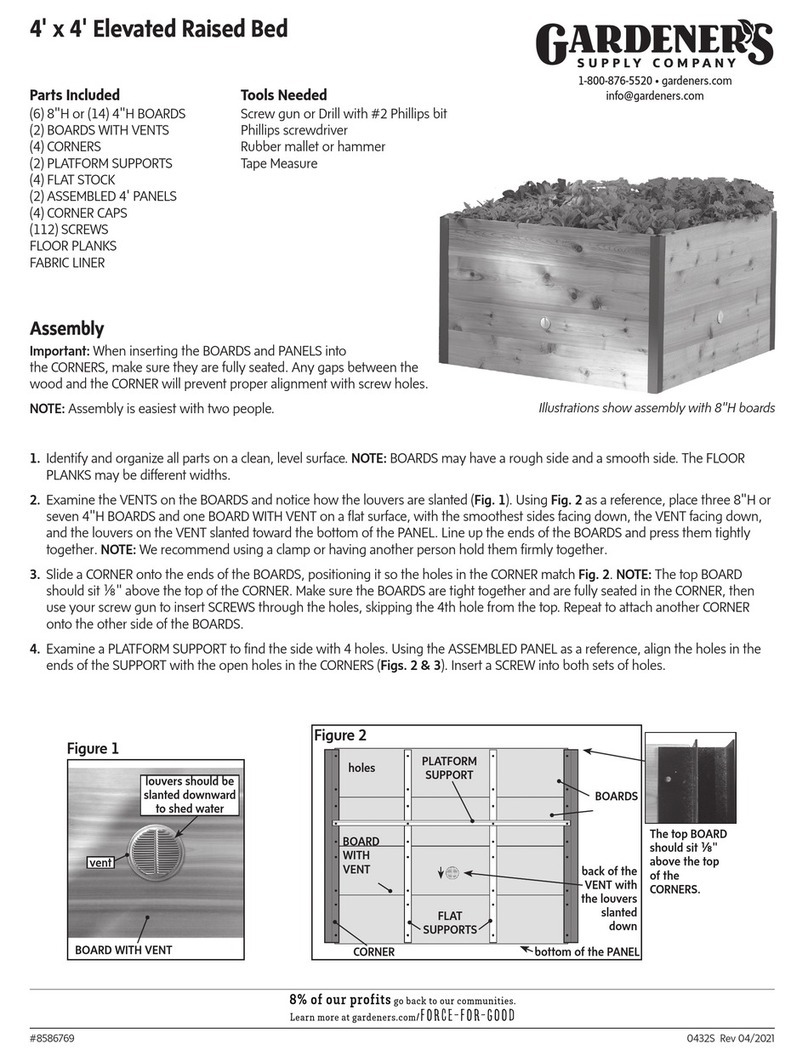
Step 9. Position the top brace of the Basket between
the two Frame Bars and let it rest on the Top Brace of
the Tractor Frame. Direct the two hooks on the lower
part of the Basket to rest on the Axle frame (Figure 5).
Step 10. Attach the Seat to the Seat Post with four
10x15mm bolts, nuts and washers. Use pliers and
a flat head screwdriver to fully tighten the bolts in
place. Note that the threaded stem of the Seat Post
has a washer and Cotter pin pre-installed. Check by
looking under the Seat to make sure the Cotter Pin is
wrapped around the Axle and secure (Figure 6).
The Seat may be raised or lowered to a desired
height simply by turning it clockwise or counter-
clockwise. For the most comfort, we recommend
adjusting the seat to a height where your feet rest
level on the ground and your thighs are parallel with
the ground.
Safety Instructions
• Not for use or for play by children.
• Test tire pressure before use. Keep tire pressure
at, or just below the maximum pressure of 30 psi.
Do not overinflate tires.
• Do not use on inclines as work seat may tip
and cause injury.
• Do not load the work seat with more than
400 lbs.
• Do not load the basket with more than 40 lbs.
• Do not load plastic tray with more than 5 lbs.
• Do not operate if any part is damaged or broken.
Figure 4.
Figure 5. (Rear View)
Bucket Basket
Figure 6.
Tray Bracket
(pre-welded)
Extend and
twist Handle
to lock into
place.
Tray
Seat
Seat Post
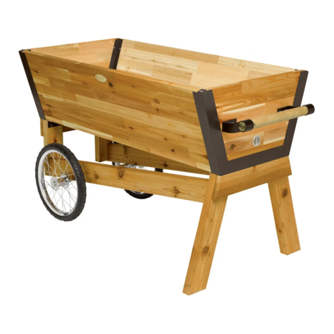
Assembled Tractor Scoot
Cotter Pin
is spread and
pinched around
the Seat Post
stem.
Front Small Reinforcing
Plates
Tray Bracket
PHONE ORDERS: 1-800-427-3363 CUSTOMER SERVICE: 1-800-876-5520
Step 2. Place the Steering Link Connector (nub side
up) onto the Front Axle Support assembly. Secure
with two 8x20 mm bolts, two 8mm washers, and two
8mm nuts as shown (Fig. 2). Use slip-jaw (adjustable
pliers) to hold the head of the bolt while tightening
the nut with a wrench (Note that you’ll first need to
undo the nuts and washers from the bolts.)
Step 3. Insert the Rear Axle through the rear Axle
Frame (Figure 2).
Step 4. Slide one Axle Sleeve onto each end of the
Rear Axle (Figure 3, Exploded View ). Using the wash-
ers packaged with the Cotter Pins, mount a washer,
followed by a Wheel (with valve stem facing out),
onto each end of the Rear Axle. Slide another washer
onto each end of the Axle. Open and slide a Cot-
ter Pin through the predrilled hole at the end of the
Axle. (Open the Cotter Pin and wrap the ends of the Pin
back around the Axle to secure the Wheels.)
Step 5. Mount a washer, followed by a Wheel
(with valve stem facing out), onto each end of the
Front Axle. Slide another washer onto each end of
the Axle followed by a Cotter Pin (Fig 3).
(Note: Axle Sleeves are not used on the Front Axle.)
Step 6. Remove the 8mm nut and washer, and large
washer from the pre-welded bolt on the Front Axle
Support. Place the Handle over the pre-welded bolt
and secure with the large washer, small washer and
nut as shown (Fig. 3a). Use the 8x25 mm nut, washer
and bolt to attach the rear hole in the handle to the
nub referenced in Step 2. Hand tighten nuts. (Figure
3a) Important: Do not over-tighten bolts on
the steering mechanism or the
steering may “freeze up.”
Figure 2.
Figure 3. Exploded View
Rear Axle
Rear Axle
Front Axle
Axle
Sleeve
Washer
Washer
Cotter Pin
Front Axle
Support
Steering Link
Connector
(Nub side up)
Frame
Handle 8x25 mm
bolt,
washer,
nut
Figure 3a.
Pre-welded
Bolt
Steering Link
Connector
