www.gastron.com
10_11
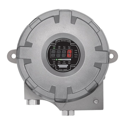
4. Name and Description of Each Part
NO NAME DESCRIPTIONS
6RS-485 signal terminal CN6isIsolationRS-485networksignalconnectionterminal(A,B).
7Sensor terminal CN1 is Sensor Connection Terminal. (RD, WH, BK, BE)
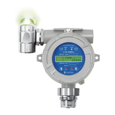
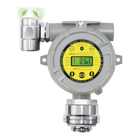
8Power lamp When power is turned on, it lights on.
9Trouble lamp It lights on when there is a fault in the circuit or sensor sensitivity, etc.
10 Alarm1 lamp It lights on when gas leaks and it exceeds Alarm1 level.
11 Alarm2 lamp It lights on when gas leaks and it exceeds Alarm2 level.
12 Function key
During parameter setting, it changes to program mode when it is contacted with magnet-bar for
2 sec or longer. (Program mode, Calibration mode, Test mode, etc.) Also, it is used to enter and
set an arbitrary data.
13 Reset key To cancel or return to the previous status during Parameter setting, use the Magnet Bar and
touch once. (Each touch returns to the previous status by one unit.
14 ↑(Up)key During conversion of mode or number, use the Magnet-Bar and touch once. Each touch converts
or changes one level. (Converts to the next level)
15 ↓(Down)key During conversion of mode or number, use the Magnet-Bar and touch once. Each touch converts
or increases displayed value by one unit. (Converts to the previous level)
16 External earth - It is an external ground for protection from external noise or strong electric field.
- Use a conductor that is 4 mm or longer when coupling ground line.
17 Mount hole Hole to fix the gas detector on external wall or other installation sites.
18 Cover fixed screw(M4) After assembling detector housing body and cover, they are fixed with hex lens bolt to prevent
detachment by external shock.
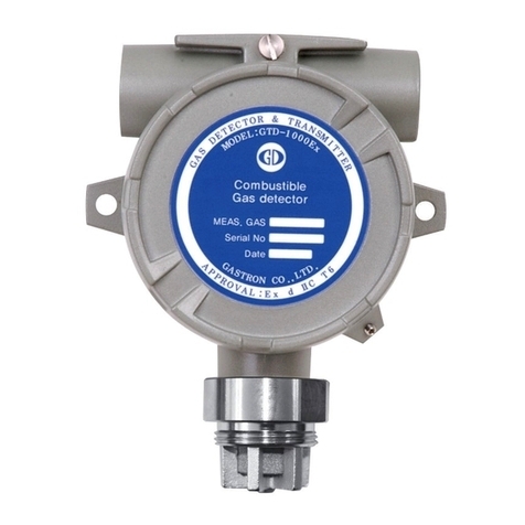
19 Sensor thread It is a mounting for gas sensor (detector).
20 Cable inlet It is provided to supply power and inlet for measured output signal of the gas detector during
installation work. As default, PF 3/4” is provided.
21 Internal earth -
It must be grounded to inside of detector for protection from external noise or strong electric field.
- Use a conductor that is 4 mm or longer when coupling ground line.
22 RS-485 Module /
HARTModule(Option사양)
It is a connector for Isolation Type RS-485 and HART network modules to communicate with PC
or PLC. To run RS-485 network, network address must be configured. Default is 1. To run HART
network, Polling-Address and Tag No., etc. must be configured.
23 Relay Contact Type
Selection Jumper
It is constructed to select A or B contact.
When it is not in ENERGIZER MODE, it operates in A contact (Normal Open) mode or B contact
(Normal Close) mode when Jumper is connected to a part marked as A silk or B silk, respectively.
In contrast, when it is in ENERGIZER MODE, connecting Jumper to A operates in B contact mode
and connecting Jumper to B operates in A contact mode.
24 Warning Light Connector It is a connector connected when a warning light is used. (Option)
25 Program Connector It is a connector for downloading the program for the product.
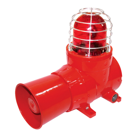
26 FRONT CASE It is an explosion-proof case made of explosion-proof plastic and emits LED light externally
through transparent window.
27 CASE RING It serves as a cover to prevent deviation of front case.
28 SEXANGLE BOLT It serves to prevent deviation after case ring assembly and is fixed by mood bolt.
NO NAME DESCRIPTIONS
29 CASE BODY It is the main body that protects internal buzzer and other parts by body.
30 BUZZER It receives signal upon an event of error and generates warning sound.
31 FIXED RING It prevents deviation of sinter filter upon external shock.
32 FLAME ARRESTER It blocks flow in of dust, debris, water, gas and delivers warning sound from the buzzer to
outside.
33 ARREST CAP It protects sinter filter from external shock.
34 LED COVER ItisajointforLEDPCBASS'Yandcoveredwithmoulding.
35 LEDPCBASS'Y It is a multi-color LED that displays status.
36 NUT It serves to fix parts to the compliment part.
37 SHAFT BODY It serves to fix parts to the compliment part.
38 CABLE WIRE It supplies power and transmits data.
[Table 1. GTD-3000TxW Components Description]
4.2. LAMP Function Description
■GTL-100runsbysyncingwiththedetectorandbythestatusofinstalleddetector.
■Innormalstatus,greenLEDlightsonandbuzzerdoesnotring.
■WhenAlarm-1signalisreceived,redLEDflickersin1secintervalandbuzzerringsin1secinterval.
■WhenAlarm-2signalisreceived,redLEDlightsonandbuzzerringscontinuously.
■WhenTroublesignalisreceived,yellowLEDlightsonandbuzzerdoesnotring.
4. Name and Description of Each Part
GTD-3000TxW
Instruction Manual


