GAT GM-820A-Dual User manual
GM-820A-Dual A/C SYSTEM MAINTENANCE CENTRE-DUAL
1
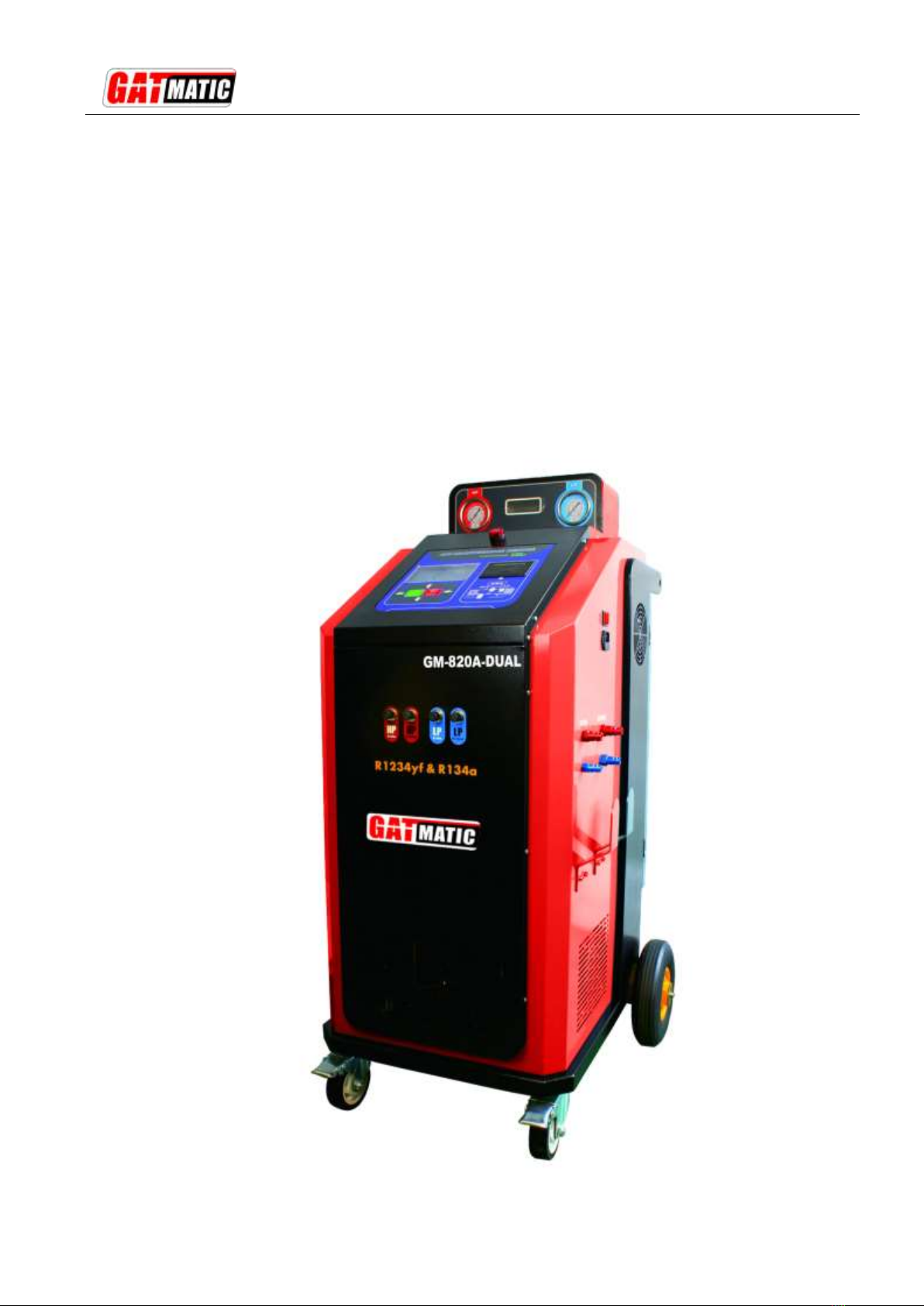
GM-820A-Dual
A/C System Maintenance Centre
R1234a & R1234yf
GM-820A-Dual A/C SYSTEM MAINTENANCE CENTRE-DUAL
2
NOTE:
1) Carefully read the user manual before using, and keep it well for future reference.
2) Carefully check the device parts list before using. For any doubt, contact GAT MACHINERY distributor
immediately.
3) Due to the product upgrade, tiny difference between the user manual and the device will not be further
noticed. Take the device as standard.
Copyright reserved! Without written agreement from GAT Machinery Co., Ltd (Hereinafter refer to
"GATMATIC "), any company or person is not allowed to copy and duplicate this user manual in any format
(electronic, mechanical, video, record or other formats).The user manual is designed only for GATMATIC
products.Any consequence caused by using the user manual to guide other device operation is not under
the responsibility of GATMATIC.
GATMATIC and its branches are not responsible for the fees and expense of the device damage and loss
due to private accident or from third party, misuse and abuse of the device, unauthorized change and repair,
or any operation and maintenance not following GATMATIC standard.
GATMATIC is not responsible for device damage or problem due to the usage of any optional parts or
consumables instead of GATMATIC original products or GATMATIC recognized products.
Declaration: Other product names mentioned in the user manual are aimed to describe the device usage.
The registered trademarks still belong to the original company.
The device is for professional technicians or maintenance and repair personnel.
Registered Trademark
GAT MACHINERY has registered its trademark in China and several other countries, logo is .
Other GATMATIC trademarks, service marks, dot names, Icons, company names mentioned in the user
manual all belong to GATMATIC and its subsidiaries. In those countries where GATMATIC trademark,
service mark, dot name, icon, company name not registered yet, GATMATIC declaim the right for its
unregistered trademark, service mark, dot name, icon, and company name. Trademarks of the other
products and company names mentioned in the user manual still belong to original registered company.
Without written agreement from the owner, no person is allowed to use the trademark, service mark, dot
name, icon and company name of GATMATIC or of other mentioned companies. You can visit
http://www.gattek.com to get contact with GATMATIC for the written agreement on the usage of the User
Manual.

GM-820A-Dual A/C SYSTEM MAINTENANCE CENTRE-DUAL
3
Safety
A. The machine is designed to be used and repaired by qualified personnel only.
B. The machine is designed to be used for R134a and R1234yf refrigerant. Other refrigerant types are not
applicable. Different types of refrigerants cannot be mixed, otherwise it is easy to cause equipment
failure or damage the air conditioning system.
C. Fill the A/C system with the quantity of refrigerant recommended by the manufacturer.
D. Keep away from moving parts and rotating elements such as cooling fans, alternators and heating
components, etc. to avoid harm.
E. Wear protective clothing gloves and goggles.
F. As automotive air conditioning pipe flushing, the operator must be fully familiar with automotive air
conditioning system and operation of the machine. Check whenever the engine is turned off that the
ignition key is turned to the full OFF position!
G. Do not expose the machine to direct sunlight or rain. Use only in well-ventilated work areas.
H. Never exceed 30 °tilt in transit process upside down is strictly prohibited.
I. Do not touch the machine high voltage power supply section, and do not maintain the machine as
power on.
J. Care of the manual.
K. We reserve the right to modify the contents of this document without prior notice to our customers.

GM-820A-Dual A/C SYSTEM MAINTENANCE CENTRE-DUAL
4
CONTENTS
1. Introduction...........................................................................................................................................5
1) Outline..................................................................................................................................................5
2) Features...............................................................................................................................................5
3) Specifications.......................................................................................................................................5
2. Functions..............................................................................................................................................6
1) Primary functions .................................................................................................................................6
2) Subsidiary functions.............................................................................................................................6
3. Operation..............................................................................................................................................7
1) Parts descriptions.................................................................................................................................7
2) First use................................................................................................................................................8
3) Preparations before Run Flushing function.........................................................................................9
4) Power On .............................................................................................................................................9
5) Flushing-Recovery............................................................................................................................. 11
6) Recovery/Recycling ...........................................................................................................................12
7) Vacuum ..............................................................................................................................................12
8) New oil adding....................................................................................................................................12
9) Recharging.........................................................................................................................................13
10) Auto. Mode.......................................................................................................................................14
11) Database..........................................................................................................................................14
12) Equipment Maintenance..................................................................................................................14
12-1) Exchange dry filter........................................................................................................................15
12-2) Clean pipe of the unit....................................................................................................................15
12-3) Calibration of load cell (operate by professionals).......................................................................15
12-4) Drain used oil................................................................................................................................15
12-5) Empty internal refrigerant .............................................................................................................15
12-6) Vacuum System Pipeline..............................................................................................................16
12-7) Change vacuum pump oil.............................................................................................................16
12-8) Discharge non-condensable gases..............................................................................................17
13) Supply tank.......................................................................................................................................17
14) System function................................................................................................................................18
14-1) Language......................................................................................................................................18
14-2) Units..............................................................................................................................................19
15) Equipment info.................................................................................................................................19
15-1) System inquiry ..............................................................................................................................19
15-2) Servicer info..................................................................................................................................19
15-3) Equipment info..............................................................................................................................19
16) Help..................................................................................................................................................20

GM-820A-Dual A/C SYSTEM MAINTENANCE CENTRE-DUAL
5
1. Introduction
1) Outline
GATMATIC GM seriesA/C system maintenance equipment is with the latest design technique which uses
the best control principle and the manufacturing process.
A/C System Maintenance Centre is intelligent equipment collecting of the A/C flushing, recovery, recycling,
recharging and other functions in one. It’s with the beautiful shape, humanized operation interface, and
advanced manufacturing processes to make the A/C maintenance professional and simple.
The machine is designed to be used for R134a and R1234yf refrigerant.
2) Features
A. For R134a and R1234yf refrigerant.
B. Fully automatic, easy to operate.
C. Internal pipeline of A/C system flushing, effectively cleared the internal greasy and fouling, to restore
the A/C system performance.
D. With forward flushing, reverse flushing, and pulse flushing functions, which greatly improve the
cleaning effect.
E. Using large-size glass tube with LED backlighting, can effectively observe the entire cleaning process.
F. Vertically installing the HP & LP gauges let the operator be able to observe the pressure parameters
timely even in the car.
G. Unique design of the pipeline to achieve the high recycling rate no matter with the gas or the liquid.
H. Easy to operate with the concise operating interface.
I. Designed with large size LCD.
J. Database.
K. Program and database can be updated.
L. With printer.
M. The self-cleaning function of the equipment can ensure that the refrigerant stored in the equipment
meets the reuse level.
3) Specifications
A. Working conditions:
Ambient temperature: 0~50°C
Relative humidity: <85%
B. Voltage input: □AC220V±10%~50/60Hz □AC110V±10%~60Hz (see as label)
C. Compressor:12.12cm3
D. Vacuum pump: 7.2m3/h,2Pa
E. Load cell for tank: 30kg/±10g, 2pcs
F. Load cell for oil bottle: 6kg/±5g
G. Tank: 12L, 2pcs
H. PAG oil bottle: 300ml
I. POE oil bottle: 300ml
J. Used oil bottle:500ml
K. LCD display: 240*128

GM-820A-Dual A/C SYSTEM MAINTENANCE CENTRE-DUAL
6
L. Working pressure: max. 20bar
M. HP gauge: -1bar~35bar
N. LP gauge: -1bar~20bar
O. Max. Work Pressure:20bar
P. Backlighting: LED
Q. Language: Chinese and English (can be customized)
2、Functions
1) Primary functions
A. Dual refrigerant system
B. Support dual refrigerant oil type
C. Automatic flushing
D. Automatic recovering/recycling
E. Automatic/manual used oil drain
F. Vacuum timing.
G. Automatic/manual new oil injection
H. Quantitative recharging
I. Each function can operate independently
J. Auto mode
K. Database
L. Print
2) Subsidiary functions
A. Parameter setting
B. Refrigerant supplement
C. Pipeline self-cleaning
D. Equipment emptying
E. Equipment vacuum
F. Electronic scale calibration (professional)
G. Machine maintenance (Dry-filter exchanger, vacuum pump oil exchanger)
H. Printer test
I. Equipment status query
J. Equipment info inquiry
K. Help
GM-820A-Dual A/C SYSTEM MAINTENANCE CENTRE-DUAL
7
3. Operation
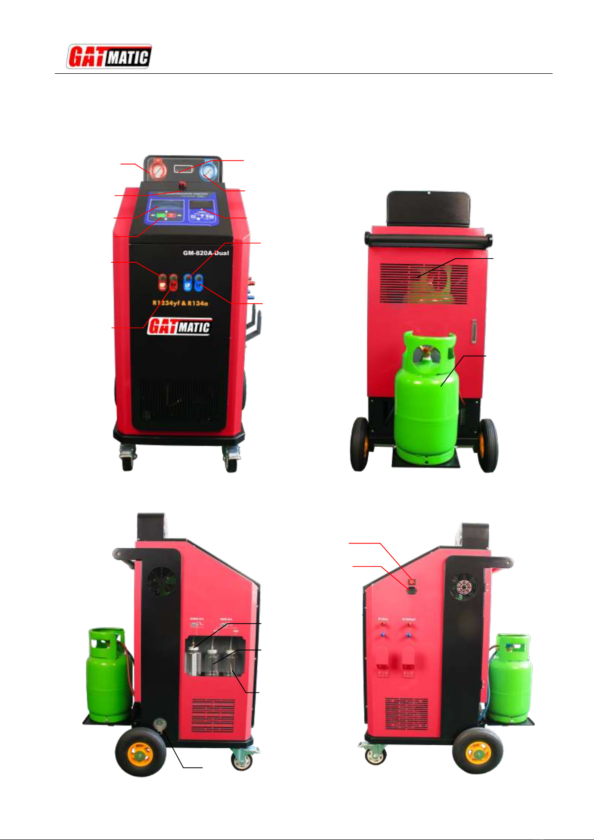
1) Parts descriptions
HP gauge
Alarm
LCD display
Keys
R134a
HP port
R1234yf
HP port
LP gauge
Printer
R134a
LP port
R1234yf
LP port
Window
Power switch
Power socket
R134ATank
R1234YF Tank
Used oil bottle
New oil bottle
POE bottle
Vacuum pump oil
observe window

GM-820A-Dual A/C SYSTEM MAINTENANCE CENTRE-DUAL
8
2) First use
A. In order to avoid damage to the electronic scale during transportation, the electronic scale is protected
when shipped. Open the back door, take out all the fillers on both sides of the tank and under the scale
pan, and loosen the supporting screw under the scale plate to make the scale handle the suspended
state.As shown in the figure below:
B. Connect the power supply and power on. Please operation as following.
C. Set the language: select one and press ENTER.
C、Set the units: select one and press ENTER
D. Install the R1234yf storage tank back of the machine.
a) Place the storage tank on the rear scale and fix it.
b) Connect the red and blue pipes to the red and blue valve interfaces of the tank, tighten them (it is
recommended to apply a small amount of stop glue), and open the two valves.
E. Connect the hoses and couplers
Loosen
GM-820A-Dual A/C SYSTEM MAINTENANCE CENTRE-DUAL
9
a) Connect the two RED hoses to the HP ports.
b) Connect the two blue hoses to the LP ports.
c) Connect the RED and BLUE couplers of R134a to the RED and BLUE pipes of R134a
respectively.
d) Connect the RED and BLUE couplers of R1234yf to the RED and BLUE pipes of R1234yf
respectively.
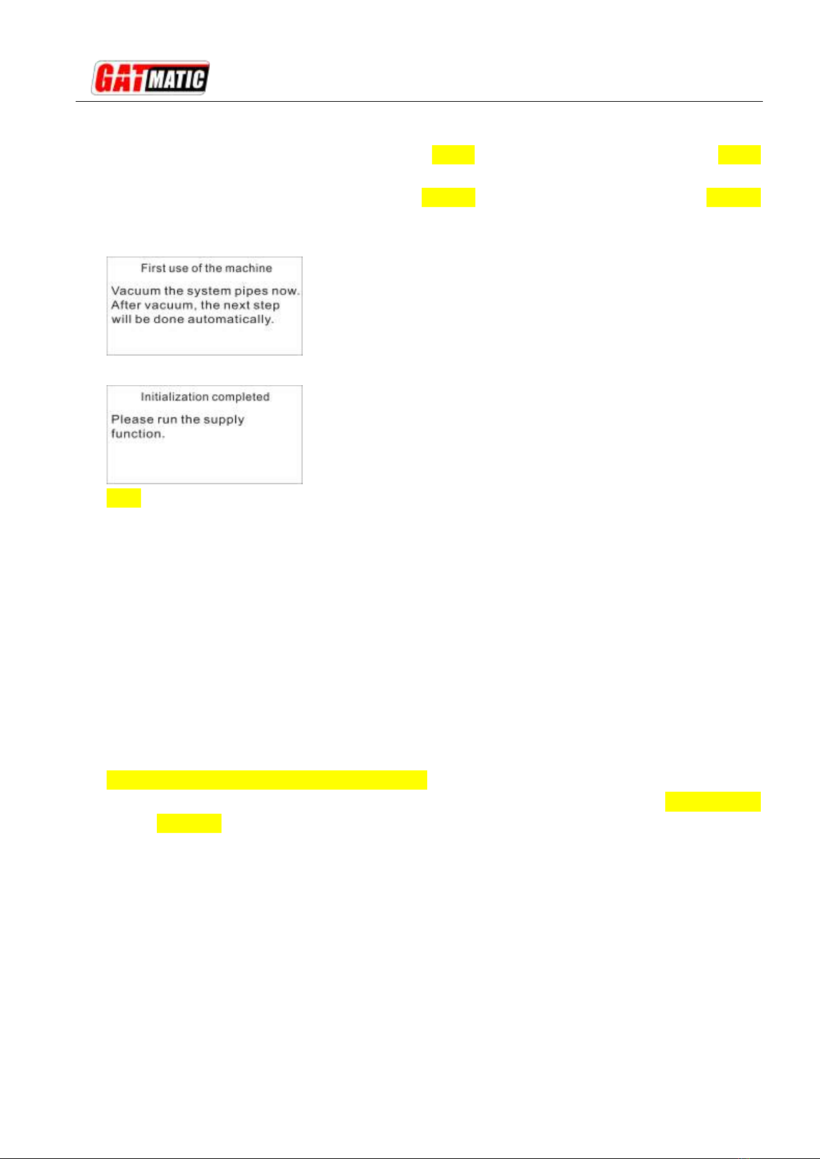
F. Initialization
G. Supply refrigerant to the new equipment (please refer to the SUPPLY FUNCTION section)
Note:
As the new equipment is empty, the Flushing and Recharging functions will not be performed.
In order to ensure all functions normal, about 4kg R134a and 4kg R1234yf refrigerant need to be
filled to the tanks. If it is not necessary to use the Flushing function, replenish at least 2kg.
H. Please read this user manual carefully before operating.
3) Preparations before Run Flushing function
A. Check the refrigerant type of the automobile air conditioning, and connect the right couplers to the A/C
service ports, and open the couplers on.
B. Start the car, and run theA/C for about 5 minutes.
C. Check whether the high and low pressure of A/C is normal. Check whether there is abnormal noise
when the compressor works. If there is any abnormality, it must be repaired first.
D. Turn off the air conditioner and turn off the engine.
E. Empty the used oil bottle. Add an appropriate amount of new oil into the new oil bottles (Note: PAG and
Poe types).
F. Turn on and prepare for work.
Warning: When the machine is running, never to run the A/C system!
4) Power On
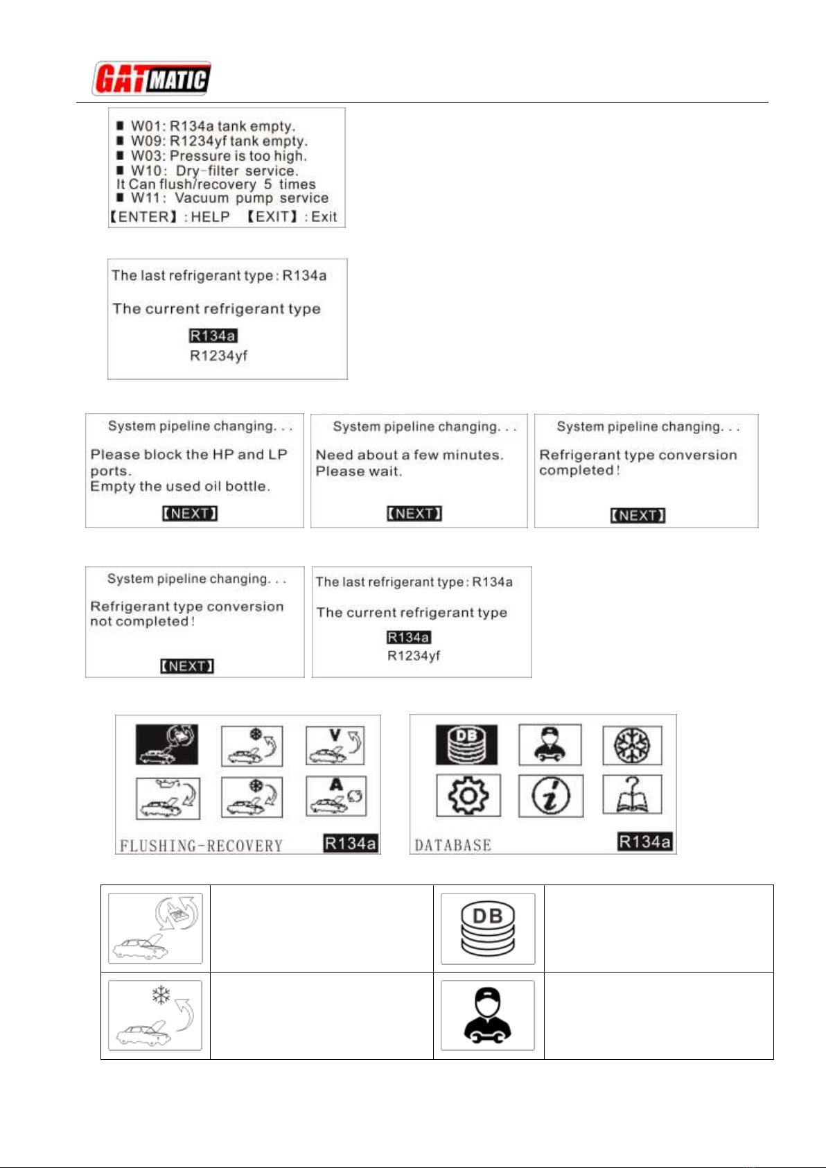
A. If the equipment detects abnormal information, it will give a prompt, which should be handled in time. If
there is no prompt message, it will go to the next interface directly.
GM-820A-Dual A/C SYSTEM MAINTENANCE CENTRE-DUAL
10
B. Select the refrigerant type: R134a or R1234yf. The default is the last operation type.
C. If the refrigerant type is different from last time, please operate according to the prompts.
If the process is terminated artificially, it will can’t be into the main function and back to the last Interface.
D. After completion, enter the function interface.
Description:
Flushing- Recovery
This function include flushing
and recovery process.
Database
Check the amount of Refrigerant
& oil
Recovery
Recovery the refrigerant of A/C
system.
Equipment Maintanance
Exchange dry-filter, Pipe-line
cleanning, Calibration load cell.

GM-820A-Dual A/C SYSTEM MAINTENANCE CENTRE-DUAL
11
Vacuum
Timing vacuum.
Supply Refrigerant
Transfer the refrigerant into the
equipment tank.
New oil adding
Fill the new oil into A/C system.
System function
Supply,Parameter
setting,Exchange filling
tank,Change refrigerant type
Recharging
Recharge quantitative.
Equipment info
System info,Servicer info,
Equipment info.
Auto. Mode
Automatically all the process.
Help
Descriptions of the alarming
code.
5) Flushing-Recovery
A. By this function, it will be able to clean out the refrigerant oil and oil sludge to exchange the refrigerant
entirely to improve the performance of compressor. And also it will recover the refrigerant remained in
the A/C system.
B. Before flushing the pipeline of automotive A/C system, please turn on A/C system and run it for 5 to 10
minutes.And set it as the lowest temperature and medium wind.
C. Turn off the automotive air conditioning.
Warning: do not start the air conditioning during the flushing process! Otherwise, it easily
causes damages to the air-conditioning and risk of accident!
D. In order to achieve good flushing performance, the flushing time should be more than 20 minutes.
General: the cleaning time for single-evaporator is 20 minutes, and that for double-evaporator is about
30 minutes. The longer the cleaning time, the better the cleaning effect.
Note: The flushing time does not include the time of recovery process. Once the flushing is
finished, the machine will run the recovery function automatically.
E. Operations:
E-1: Select the Flushing Function and press the ENTER key.
E-2: Set the flushing time.
E-3: Press the ENTER key to start.
F. During the working, it can automatically carry out forward, reverse and pulse cleaning, and
automatically discharge the used oil separated from the cleaning into the old oil bottle.
G. After the cleaning process, it will automatically recover the refrigerant. According to the ambient
temperature and the structure of the A/C system, the recovery process will last for 10-30 minutes.
Please do not manually terminate the work.
H. When finished, it’ll stop automatically. And it will discharge the separated used oil again, and then shut
down automatically and give a prompt.

GM-820A-Dual A/C SYSTEM MAINTENANCE CENTRE-DUAL
12
Notice: it’s normal for that there have action sound of the solenoid valve during the working
process. Please do not stop it. The used oil can be drained out automatically.
Warning: In case of sudden power failure or accidental termination during the Flushing-Recovery
process, please re select the Flushing-Recovery function. The cleaning time can be set shorter and
then run again. It is important not to operate other functions.
6) Recovery/Recycling
A. By this function, it will recover the refrigerant remained in the A/C system.
B. Operations:
B-1: Select the Recovery Function and press the ENTER key.
B-2: Press the ENTER key to start.
B-3:After recovery over, it’ll drain the used oil automatically.
C. When finished, it will discharge the separated used oil, and then stop automatically.
7) Vacuum
A. By this function, it will clean the water vapor out from the A/C system.
B. It should be more than 15 minutes. Generally, it needs 15 minutes at least for the air conditioning only
with front wind and 20 minutes for with the front and rear wind.
C. Operations:
C-1: Select the Vacuum Function and press the ENTER key.
C-2: Set the vacuum time.
C-3: Press the ENTER key to start.
D. When finished, it’ll stop automatically.
8) New oil adding
A. It must be able to do after vacuum process.
B. Pour new oil into the new oil bottle.
Note:
1) Add new oil more 20ml than the used oil drained out to avoid the air into the air
conditioning system.
2) Pour the new oil into the corresponding oil bottle. PAG oil into the PAG bottle and POE oil into the
POE bottle. The two types of oil cannot be mixed, otherwise it will cause damage to the air
conditioning system. Please check the vehicle technical manual or label, do not add the wrong
type!
3) If a non-vacuum state is detected, the function cannot be run.
C. Operations:
C-1: Select the New oi adding Function and press the ENTER key.
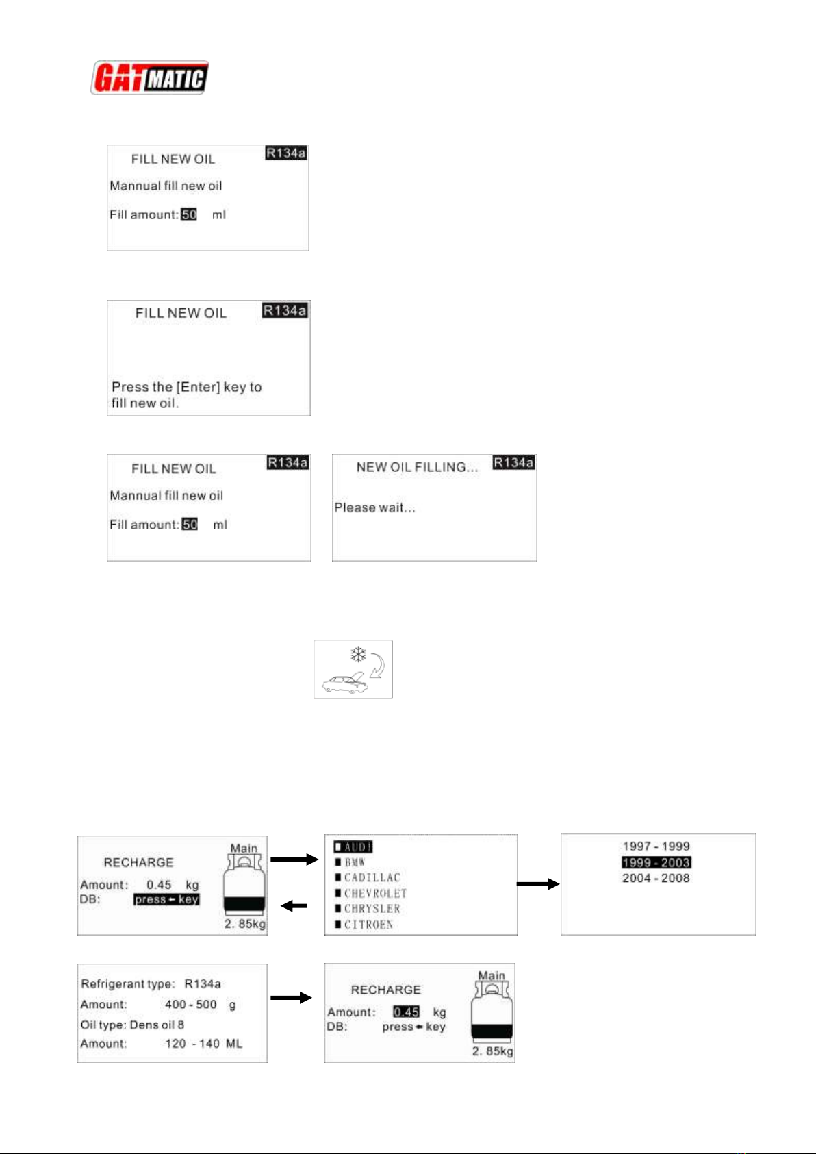
GM-820A-Dual A/C SYSTEM MAINTENANCE CENTRE-DUAL
13
C-2: Set the oil type. Must be correct!
C-3: Select method: you can choose manual control, or set the filling amount.
C-3.1 If you select Manual control, press and hold ENTER key for injection, and release the key to
stop.
C-3.2 If set the filling amount, press ENTER key after set, and it will stop automatically.
9) Recharging
A. Select the Recharging Function and press the ENTER key.
B. Set the recharge amount.
C. Press the ENTER key to start.
D. When finished, it’ll stop automatically.
Note: The recharging amount setting as following.
Method 1: Set the amount directly.
Method 2: Set the amount by the database. Steps as following:
Press
key
ENTER

GM-820A-Dual A/C SYSTEM MAINTENANCE CENTRE-DUAL
14
Note: In the recharging process, if shows the menu, it
means that you need to turn on the car air-conditioning to
complete the recharging process. Later, you should
supply new refrigerant into the tank.
10) Auto. Mode
A. Under this mode, all of the functions can be run full automatically after setting the parameters.
B. Before running, must drain out the used oil entirely and fill enough new oil into the new bottle. Pay
attention to the oil type.
C. Operations:
C-1: Select theAuto. Mode Function and press the ENTER key.
C-2: Set the all parameters.
or
C-2: Press the ENTER key to start.
D. When finished, it’ll stop automatically.
11) Database
Here you can read the refrigerant type and filling amount and the refrigerant oil type and
filling amount of the automotive.
12) Equipment Maintenance

GM-820A-Dual A/C SYSTEM MAINTENANCE CENTRE-DUAL
15
12-1) Exchange dry filter
A. The dry filter must be exchange when it reaches the life time. There will give a message.
B. If not exchange the dry-filter timely, it will not be able to run the recovery, flushing and supplying
functions.
C. Operations:
C-1: Please check the ID of the dry-filter at the label. Which is the SN.
C-2: Select Exchange dry-filter Function and press ENTER key.
C-3: Input the ID.
C-4: And then do step by step as the information.
Note: Please attention the mounting direction of the dry-filter.
12-2) Clean pipe of the unit
A. Through this function, it can effectively remove the oil mist and trace moisture in the internal pipeline of
the equipment, and ensure that the system is clean and pollution-free.
B. After a period of use, such as 3months, it should be run this function.
C. Operations:
C-1: Power on, select refrigerant type, then select Equipment Maintenance.
C-2: Select Clean Pipe of The Unit function and press ENTER key.
C-3: Connect the hoses and couplers well to the coupling side of the equipment, and open the
couplers.
C-4: And then press ENTER key to run.
Warning: this function is performed according to the type of refrigerant.
12-3) Calibration of load cell (operate by professionals)
A. When the load cell is not precise, it needs to be calibrated.
B. You need input the password 1510 before use this function.
C. If do the calibration of main tank load cell, please prepare a 10~20kg weight.
If do the calibration of oil bottle load cell, please prepare a 1-3kg weight.
D. Follow the prompts step by step.
Note: if here have some programs, please check according to the messages.
12-4) Drain used oil
A. It can control the used oil drained manually.
B. Select Drain Used Oil function and press ENTER key.
C. Press and hold ENTER key to drain, and release the key to stop.
12-5) Empty internal refrigerant
A. Through this function, the refrigerant in the equipment can be emptied.
B. It is necessary to use another refrigerant recovery equipment (say as MM).
C. Operations:

GM-820A-Dual A/C SYSTEM MAINTENANCE CENTRE-DUAL
16
C-1: Connect the HP & LP ports of the equipment with the HP & LP ports of the MM. Pay attention to
the type of refrigerant.
C-2: Select Empty Internal Refrigerant function and press ENTER key.
C-3: Confirm the pipes connected well, and press ENTER key.
C-4: Run Recovery function of MM.
C-5: After recovery end, stop and power off the MM. And then press ENTER key to the next step.
C-6: Wait for a moment. When it shows END, the pipes connected with two equipment can be
disconnected.
C-6: Run the Vacuum System Pipeline function.
Warning: this function is performed according to the type of refrigerant.
12-6) Vacuum System Pipeline
Through this function, the internal pipeline of the equipment can be completely vacuumed to the factory
state.
Before run this function, it must do the Empty Internal Refrigerant function.
Operations:
C-1: Power on, select refrigerant type, then select Equipment Maintenance.
C-2: Select Vacuum System Pipeline function and press ENTER key.
C-3: Connect the hoses and couplers well to the coupling side of the equipment, and open the
couplers.
C-4: And then press ENTER key to run.
Warning: this function is performed according to the type of refrigerant.
12-7) Change vacuum pump oil
A. When the pump oil became cream or machine display maintenance message, the vacuum pump oil
must be changed.
B. If not change the pump oil in time, the vacuum pump will be easily damaged.
C. Operations:
C-1: Open the back-down cover.
C-2: Unscrew the block of the drain port to drain the old oil out entirely. Then re-back the block to the
drain port.
Note: the oil drain hole is on the same side of the window or at the bottom. There are some differences
in specifications.
C-3: Unscrew the cap of the fill port and then fill the new oil slowly into the vacuum pump until the oil
level reach at the center site. Then re-back the cap to the fill port.
Window
Drain port
Fill port

GM-820A-Dual A/C SYSTEM MAINTENANCE CENTRE-DUAL
17
Note: the new vacuum pump oil cannot be filled too much into the vacuum pump otherwise it will spray
out when working.
C-4: Re-back the cover.
12-8) Discharge non-condensable gases
A. Due to some uncontrollable reasons, after a period of time, some incompressible gas will be
accumulated in the tanks. If the gas is too much, it will cause abnormal operation of the equipment.
B. It is necessary to discharge non-condensable gases regularly, and it is recommended to do it once a
month (if the use frequency is low, the exhaust cycle can be extended). Or, when the machine appear
the High-pressureAlarm, it need do it immediately.
C. Operations:
C-1: Remove the rear refrigerant tank and place it aside. Note: do not remove any pipes!
C-2: Open the back door, and there are two exhaust valves in the left middle of the machine. Open the
valve slowly to discharge non-condensable gases.
Attention: slowly rotate the valve handle, stop the rotation when you hear the exhaust sound, and let
the exhaust stand still.
Left valve -R1234yf tank exhaust Right valve - R134a tank exhaust
C-2: The exhaust time is about 20 seconds.
Warning: when exhausting, it is necessary to cut off the power supply and carry out it in a ventilated
environment, and no fireworks are allowed!
13) Supply tank
R1234yf exhaust valve
R134a exhaust valve

GM-820A-Dual A/C SYSTEM MAINTENANCE CENTRE-DUAL
18
A. If the refrigerant amount in the main tank is less 3kg, the flushing function can’t run any more, and if
less 1kg, the recharging function also can’t run any more, until supply enough refrigerant into the
machine.
B. Operations:
B-1: Power on, select refrigerant type, then select Supply Tank function.
B-2: Select if use the supplying connecter:
B-3.1: If use the supplying connecter, the pipeline connection is as follows:
Fitting the supplying connecter to the port of fresh refrigerant tank.
Note: it should connect to the liquid port of fresh refrigerant tank. If has no liquid port,
please place the fresh refrigerant tank upside down.
Connect the HP coupler to the supplying connecter and open it.
B-3.2: If don’t use the supplying connecter, the pipeline connection is as follows:
Connect the port of fresh refrigerant tank to the LP port of equipment.
Note: it should connect to the liquid port of fresh refrigerant tank. If has no liquid port,
please place the fresh refrigerant tank upside down.
B-4: Open the valve of fresh refrigerant tank.
B-5: Set the supplying amount and press ENTER key to run.
Note: Amount of supplying:Setting the amount according to remain amount in the tank.
Suggestion: supplying amount = (4.5~5) - remained amount.
B-6: When alarming, please close the valve of the fresh refrigerant tank, upright it and press ENTER
key to confirm.
B-7: After the refrigerant in the pipeline is recovered, the equipment stops automatically. Then install
the quick coupling.
Special declare:
When the refrigerant is supply to the new equipment, due to the vacuum state of equipment system, some
refrigerant will remain in the pipeline and components when supplying refrigerant to tank, resulting in the
actual amount of refrigerant recovered will be more than that shown by the equipment, which is normal.
14) System function
14-1) Language
Change the language
GM-820A-Dual A/C SYSTEM MAINTENANCE CENTRE-DUAL
19
14-2) Units
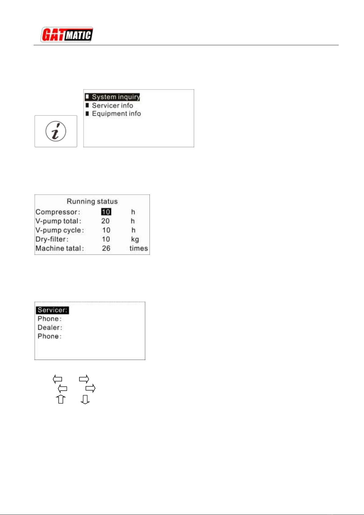
15) Equipment info
15-1) System inquiry
Here you can check the working status of the machine.
15-2) Servicer info
Here you can set and check the servicer and dealer information.
The way for setting:
Press and keys at same time into the setup state.
Use the and keys to select position
Use the and keys to set the content.
15-3) Equipment info
Here you can check the SN, hardware version, software version etc.

GM-820A-Dual A/C SYSTEM MAINTENANCE CENTRE-DUAL
20
16) Help
Here you can check all of the help messages.
Declare:
We reserve the right to modify the contents of this document without prior notice to our customers.
This manual suits for next models
2
Table of contents
Other GAT Cleaning Equipment manuals


