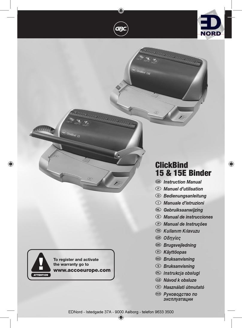
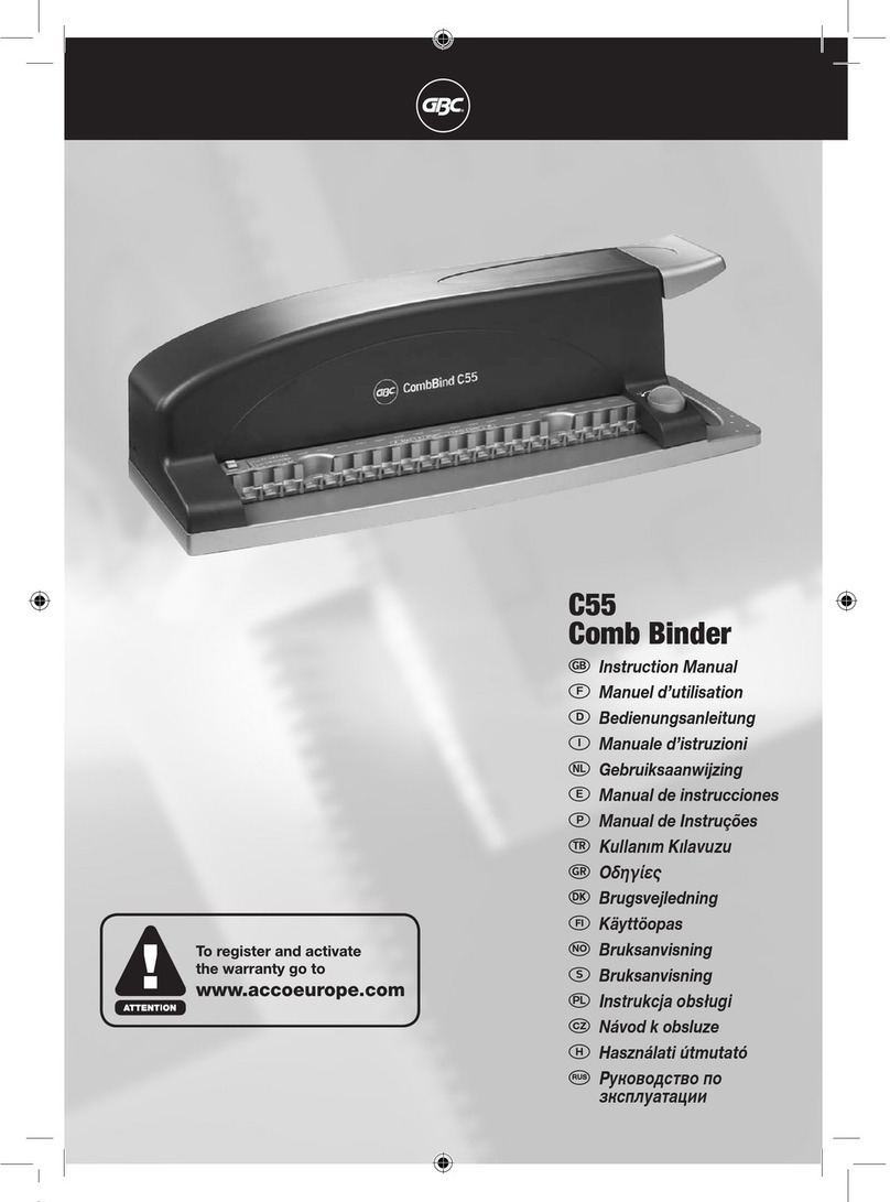
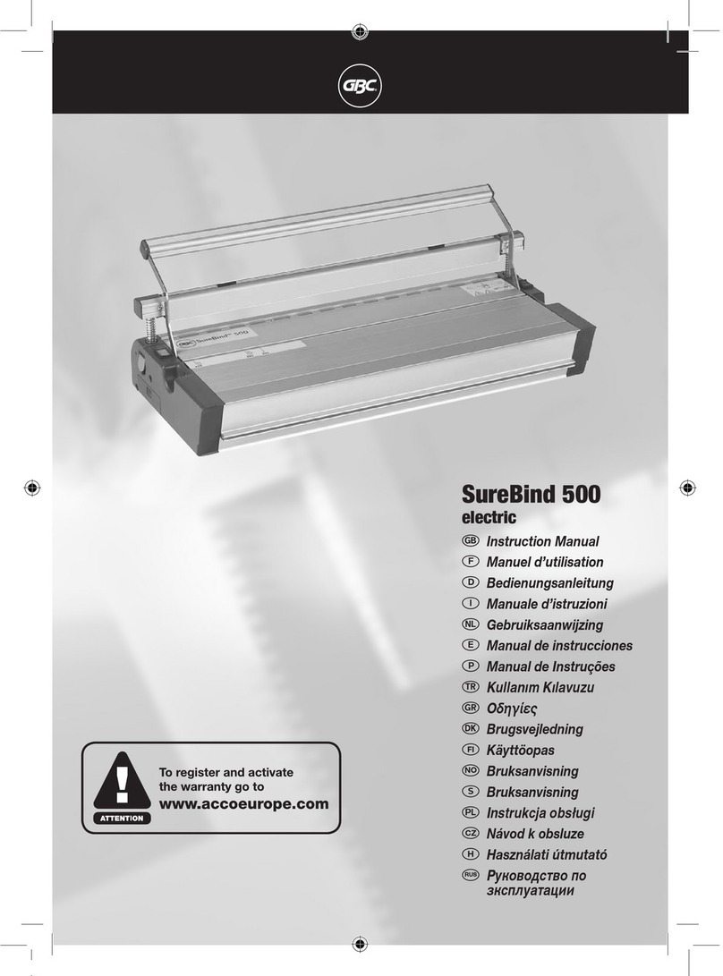
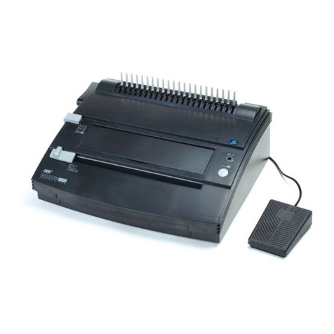
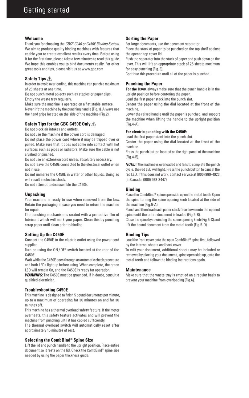
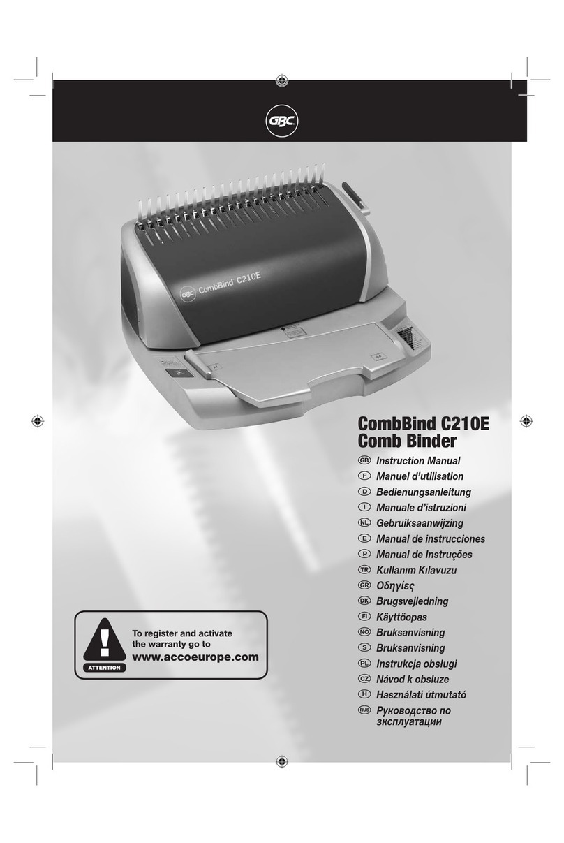
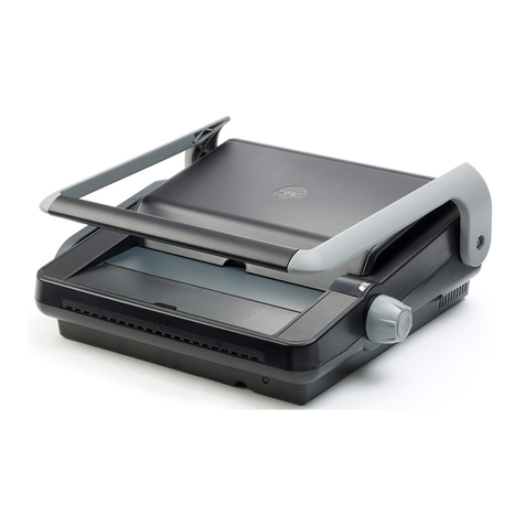
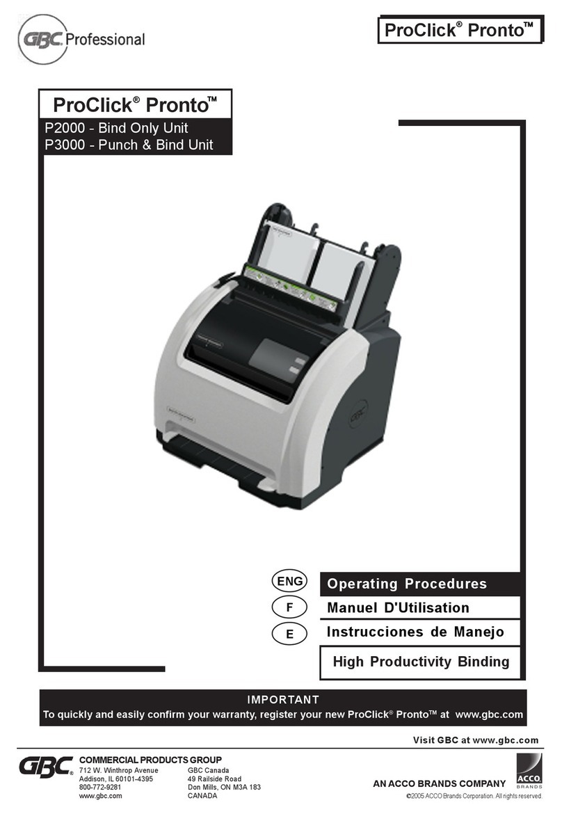
GBC GBC Proclick Pronto Operating manual

1
ProClick®Pronto™
Technical Service Manual
P2000 – Bind Only Unit
P3000 – Punch & Bind Unit
GBC TECHNICAL SERVICE & SUPPORT, REVISION: 04/29/2006

2
COPYRIGHT 2005
No part of this publication may be
reproduced in any form without
expressed written permission from
General Binding Corporation
Printed in the USA

3
TABLE OF CONTENTS
SECTION TOPIC PAGE
No.
1.0 Introduction 4
2.0 Specifications 5
3.0 Installation Procedures 6
4.0 Operating Instructions 7
5.0 Troubleshooting 9
6.0 Disassembly / Assembly / Adjustments 18
7.0 Maintenance Procedures 20
8.0 Parts List 21
9.0 Supplies and Recommended Spare Parts List 85
10.0 Additional Information 88
Glossary of Terms 89

4
1.0 INTRODUCTION
ProClick®Pronto™ system:
The GBC ProClick®Pronto™ is designed for easy operation. It is ruggedly built and
light enough for use on any table or desk.
The ProClick®Pronto™ is a unique binding system that incorporates several features
designed to make the process of mechanical binding as easy as 1-2-3 for the average
office worker.
The ProClick®Pronto™ is also an ideal solution for quick and professional binding.
The ProClick®Pronto™ is a unique binding system that incorporates several unique
design features:
•The User Interface Panel guides the user through the binding process with
ease.
•The ProClick®Pronto™ provides an electronic measuring device that indicates
to the user the spine size required just by placing the document into the
document sizer.
•The ProClick®Pronto™ handles the spine for you. Simply slide the spine
cassette into the spine slot. ProClick®Pronto™ will automatically feed the
spine onto the document.
ProClick®Pronto™Service Manual
This manual has been prepared to acquaint you with the machine and its service.
Please read it carefully. This manual is developed to work with other information
sources you will find on your Technical Service WEB site including:
•The official ProClick®Pronto™ Operator Manual
•The ProClick®Pronto™ Parts Catalogue
•The ProClick®Pronto™ Electrical Schematic
•Technical Bulletins and Alerts
Refer to this web site frequently as feedback from the field results in constantly
updated reference material. If you see a problem that is not covered in any of the
documentation, report it to Technical Support so that it can be added to the
documentation to assist other Technicians on future calls.

5
2.0 SPECIFICATIONS
P3000 / P2000
Binder Paper Size Letter 11 x 8.5 inches
Binding Diameter Range Up to 100 sheets or .400” (10mm) maximum with
largest element. (Sheet capacity based on 20 lbs.
(75 gm2) bond paper.
See sheet capacity guide below
Machine Weight P3000: 82.5 lbs (37.4kgs)
P2000: 68.2 lbs (30.9kgs)
Packaged Weight P3000: 85.8 lbs (38.9kgs)
P2000: 71.5 lbs (32.4kgs)
Dimensions
W x H x D 19” x 21” x 19”
(480 mm) x (532 mm) x (488 mm)
Packaged Dimensions
W x H x D 26” x 26” x 28”
(655 mm) x (655 mm) x (700 mm)
Electrical Amps
Frequency
Voltage
Power
2.5 A
60 Hz
115V
220 Watts
751 Btu
Agency Approval cCSAus (Lt)
Tuv (A4)
Required Testing FCC (Lt)
EMC (A4)
SHEET CAPACITY GUIDE:
Approximate Max.
Sheet Capacity Spine Type Spine Size
40 Small 5/16” (8mm)
70 Medium ½” (12mm)
100 Large 5/8” (16mm)

6
3.0 INSTALLATION PROCEDURE
The ProClick®Pronto™ is a Desktop category machine that does not require the
assistance of a Technician for Installation.
If the customer runs into difficulty during the installation and set-up of a ProClick®
Pronto™, keep the following points in mind.
•Shipping damage can occur from time to time. Any damage should be
reported to the carrier as soon as possible for a shipping claim. Remember
that our packaging was designed to prevent damage under the guidelines of
the National Trucking Association for normal handling of packages at this
weight. Throws or drops beyond this rating will generally resulted in what is
called “hidden damage” due to the fact that the packaging will tend to show
very little or very slight damage but the force of the drop is transmitted to the
contents.
•Every ProClick®Pronto™ is shipped with a Power Cord and a bound Operator
Manual.
•IMPORTANT: A ProClick®Pronto™ will only work properly when a ProClick®
Pronto™ hole punch is used. This hole pattern may at first be confused with a
industry standard, Twin Loop 3:1 square hole pattern but the true ProClick®
Pronto™ hole is specially enlarged to allow for:
oEasier automatic insertion of the element through the book.
oEasier page turning of the completed document.
•GBC offers the ProClick®Pronto™ hole pattern for all of it’s major punch
systems.
The ProClick®Pronto™ should be placed on a secure, stable table or counter capable
of supporting 175 lbs. This is to account for the potential of stack of books, covers
and supplies that may be stacked beside the machine.
The ProClick®Pronto™ should be located close to a power outlet.
The customer should have a place close by the machine to keep the Operator Manual
and the business card of the Technician and Sales Representatives for future
reference.
Remind the customer to register their new ProClick®Pronto™ at www.gbc.com to
confirm their warranty.

7
4.0 OPERATING INSTRUCTIONS
The official Operator Manual is available on the GBC Technical Service web site. Be
sure to read the Operator Manual carefully as many service calls related to a new
installation are due to operator misunderstanding of the proper operating procedures.
To avoid duplication of labor to update multiple documents, we will not recreate the
entire Operator Manual in this space, but we offer some key points for the Technician
to be aware of with respect to operation tips.
If the customer runs into difficulty during the installation and set-up of a ProClick®
Pronto™, keep the following points in mind.
•The P3000 punch and bind combo system is intended for light duty general
office application. For higher production, it is recommended that a customer
use one of the other punch systems made by GBC.
•Time out feature: The ProClick®Pronto™ will time out and revert back to the
first step if the bind cycle is not activated for two minutes. This means you will
need to start the sequence over again from the beginning by inserting the
document into the document sizer slot so that the system can identify the
size.
•Alignment of punched holes is extremely critical. If a sheet or two is punched
without care and the holes do not line up, the ProClick®Pronto™ will not be
able to force the element spines through the holes to form a proper closure.
If you discover operator errors or confusion not explained in the Operator manual, be
sure to notify GBC Technical Support so that that information may be added to future
versions of either the Operator Manual or the Technical service Manual.
As a supplement to this service manual, a series of videos were shot to acquaint the
Technician with operation tips, repairs and maintenance. Use the videos to obtain a
graphical image of the actions being taken and use the following text as you written
reference notes.
BASIC OPERATION:
Refer to the Video entitled “Basic Operation” as you review the following text.
Power On:
•Turn the power ON, using the I/O switch at the rear of the machine.
•Insert the document to be punched into the punch tray.
•Align paper to the left of the tray.
Note: A maximum of 15 sheets can be punched at a time. Do not attempt to punch
more than 2 plastic covers at a time.
Press the "PUNCH" switch to activate the hole punch (Model P3000 only).

8
4.0 OPERATING INSTRUCTIONS (Continued)
Binding:
Place the document into the document sizer for the machine to identify the document
size.
The machine identifies the document in 3 different sizes:
1. Large
2. Medium
3. Small
So document size is small, insert the ProClick®spine size "SMALL" with the label
facing you. Insert the punched document into the binding slot. Punched side first. 2
LED lights will illuminate when the document is in proper position. Press "BIND" and
remove the document after the binding is complete.
Spine Opener:
To unbind the book insert the wedge of the spine opener tool into the loops of the
ProClick®spine and pull. This opens the spine allowing you to edit the documents.
•To empty the chip tray, pull and remove the tray.
•Empty the contents and return the tray to its position.
•If the tray is not secure, the machine will not operate.
Hiding the Spine:
Refer to the Video entitled “Hiding the Spine” as you review the following text.
•In order to hide the spine of a finished document, you must first assemble the
document, as you want it to be once complete.
•Then fold the back cover to the front with the “Finished sides face-to-face”.
•Bind the document in then orientation.
•Once the document is bound, fold the back cover around again to the back.
•Now the spine of the element will be hidden between the back cover and the
last page of the document.
Plastic cover tip: When punching a plastic cover, you may find it works best to
sandwich the covers between 3 sheets of plain paper. Then simply press the
“PUNCH” button to punch the covers. This method improves on the life of the Die
set.
Clearing a Jam:
Refer to the Video entitled “Clearing a Jam” as you review the following text.
•To clear a jam open the cover.
•Lift the tray and remove the element.
•The LED screen will walk you step by step through the proper procedure.
•After removing the element lower the tray and close the cover.
•After you have cleared the jam, the binder will run through a 4 cycle.
•After the 4th cycle, you will need to open the cover and remove the element.
•The binder is now clear and ready to use.
•To remove the jam from the Punch assembly rotate the fan in a clockwise
direction until the die rises enough to remove the document.
•After powering the machine, the die will automatically move to its home
position.

9
5.0 TROUBLESHOOTING – Theory of Operation
5.1 Theory of Operation
The Pronto™ is a semi-automatic mechanical binding system that uses plastic fingers
to apply force on the ProClick®elements for closing. This force is applied through a
pair of spring plates. The motion of the spring plate assembly is activated by a bind
motor that drives a cam to activate the bind cycle.
On the P3000, an additional punch assembly is mounted on the front of the machine.
The maximum capacity on the punch is 15 pages (based on 20# bond) and 2 sheets
of plastic. Overhead transparencies should not be punched.
5.2 Theory of successful binding
To obtain the ultimate in a successful bind, the following process should be followed:
1. Punch the documents for binding with the ProClick®hole patterns. This is shown
in appendix A. It is preferable that the complete document is punched on the
same system to avoid paper misalignment.
Note: the ProClick®pattern is not the same as a standard 3:1 Twin Loop Wire
pattern because for ProClick®to operate properly, the holes must be slightly
larger. GBC offers the ProClick®pattern for most of the major interchangeable
punch machines to satisfy a variety of customer needs. The P3000 Pronto™
punch is intended for general office use, not in-plant or print-for-pay
operations where a Magnapunch or Ap-2 would be better suited.
2. Insert the punched document into the sizer to check for the correct spine size.
3. The machine will indicate the correct spine size. Pronto™ will allow the user to
use a larger spine for smaller document sized but not vice-versa. However, it is
important to have the correct element size for optimum results.
4. The holes of the documents should all line up. In order to hide the spine, the
back cover should be flip to the front prior to inserting the document into the
bind throat.
5. Insert the aligned document into the bind throat. After inserting the document,
check for holes alignment through the lit LEDs on both sides of the document.
Paper needs to be completely aligned for optimum results.
6. Press bind when User Interface says “Ready to Bind”
7. After binding, the machine will ‘Beep’ to indicate that the bind document is
ready.
8. Remove document by pulling the document up along the face of the paper deck.
5.3 Mechanical Systems
Sizing
oSizing for binding is activated by the element size inserted into the
cartridge pocket. Machine sizing does not move corresponding to the
sized document.
oA small PCB, 3 sensors optical sensors and a plastic rocker arm on the
left rail of the cartridge pocket detects the element size and informs
the systems of the size of elements.
oUpon detection of the element/cartridge size, the sizer motor (DC
Motor) will move the spring fingers to the designated size location. The
cams which the document sits on will also rotate to the designated
location to match the element size. This is all done through gears to
the left of the machine.
10
5.0 TROUBLESHOOTING – Theory of Operation (Continued)
Binding
oWhen the “Bind” mechanism is activated, the bind motor (AC Motor)
will drive the 2 sets of cams on the sides of the machine.
1st set of cams are the large white plastic cams on the side of
the machine. The inner rails inside the cam drive the spring
plate assembly. The outer cam drives the rotating shaft that
holds the spines while the element is being closed by the
binding fingers.
2nd set of cams is a silver/bronze colored cam behind the white
cam. This smaller cam drives the spine holder bracket (Spine
holders are the gray colored plastic fingers that holds the spine
when it is being closed) to move back and front as they are
going through the motion binding motion.
Punching
oThe punch system is driven by a universal motor that is located right
behind the punch. This punch has 15 sheets of 20lb bond paper
capacity and is a non-commercial punch.
5.4 Electrical Systems
Main PCB: Main control board responsible for the control of all electrical
components in the machine.
User Interface: User interface is connected to a 5V output from the main
PCB as shown in the electrical diagram. The speaker for the “beep” is located
on the user interface as well.
Paper Tray and Clip Tray Sensors: There are 2 sets of sensors for the
P3000 and 1 set for P2000 to detect for tray full signals the sensors are
connected directly to the main PCB.

11
5.0 TROUBLESHOOTING – Troubleshooting Guide Chart
5.5.1. ISSUE : Element Jam Often
REASON / LOGIC : Jam normally occurs when element is not fed correctly
into the bind throat.
Root Cause Location Solution
Check spine holders
-Are any spine holders
bent?
Open front cover If bend, Temporary Solution:
Break spine holder at bend
point
Long Term Solution:
Change spine holder that is
bend (See online guide)
Check retention screws
(3 screws)
- Are they loose?
Behind the paper Deck
Tighten and apply locktite on all
3 screws
Check location of bottom
clip stripper
-Clip stripper location
should be tested using
the Large element
settings
-At large settings, bottom
clip should be out of
sight when looking
parallel down into the
element slot
Between spine holder
number 4/5 and
13/14, metal piece
protruding from below
Insert large element into the
element slot, and let the sizer
move to large position.
At this position, check the
location of the bottom clip
strippers (shown in online
guide) and ensure that they are
clear of your line of sight
looking down from the element
slot.
If they are not, release the 4
screws holding the clip strippers
and rotate the stripper towards
the front and away from the
line of sight from the top of the
element slot
Broken clips or elements
getting stuck beside spine
holders
- Check for clearance
between spine holders
and closing fingers.
Between spine holders
especially on number
4/5 and 13/14
Clear all loose elements or
broken clips from the bind
throat.
Check element belt
-Are the belts straight?
-Are the clips in place?
Binding elements Align the binding element and
let it sit against a straight edge.
If the element bends, please
inform GBC service help desk
and record batch numbers from
the element box.
How many cycles?
-If over 15000 cycles ->
Check spine holder down
cam. Cam has life of
over 15,000 cycles
-wear can be detected if
there are golden
shavings under the cam.
Spine holder cam is
between the large
white gears and the
frame on both sides of
the machine.
If the spine holder down cam is
worn, gold shavings under the
white gears, change the spine
holder down cam. Instructions
are shown in the online guide.

12
5.0 TROUBLESHOOTING – Troubleshooting Guide Chart
(Continued)
5.5.2. ISSUE : Element unclosed on one end
REASON / LOGIC : This occurs when element is inserted too quickly on one
end into the bind throat causing it to push the element
over the element grip area on one side. The side that is
open is the area where the element is overfed into the
bind throat.
Root Cause Location Solution
Check element for bending
signs
Binding elements Align the binding element and
let it sit against a straight edge.
If the element bends, please
inform GBC service help desk
and record batch numbers from
the element box.
Check to ensure tension
springs are attached on
both sides
Top left and right
corner on machine Both springs should be
attached. Replace spring if
broken
Check split and push
fingers
-Split and push fingers
should be at the same
level across
At the back end of the
machine If split and push fingers are not
level, remove and aligh them
against a flat edge. The split
and push fingers bend slightly
downwards at an angle but
should be level across.
How many cycles?
-If over 15000 cycles ->
Check spine holder down
cam. Cam has life of
over 15,000 cycles
-wear can be detected if
there are golden
shavings under the cam
Spine holder cam is
between the large
white gears and the
frame on both sides of
the machine
If the spine holder down cam is
worn, gold shavings under the
white gears, change the spine
holder down cam. Instructions
are shown in the online guide.
5.5.3. ISSUE : Bind cycle did not pause.
REASON / LOGIC : There is a sensor that helps indicates to the machine on
when to pause.
Root Cause Location Solution
Check pause sensor.
Ensure position is correct
-If trigger flag could be
out of alignment with
sensor (left of machine)
-Broken sensor?
2 sensors (PCB) on
the right side of the
machine
Re-align by moving the sensors
(2 screws).
If sensors are broken/damaged,
replace sensors.

13
5.0 TROUBLESHOOTING – Troubleshooting Guide Chart
(Continued)
5.5.4. ISSUE : Motor cycles when press “BIND” but no motion.
REASON / LOGIC : Motor and gears have disengaged.
Root Cause Location Solution
Check motor drive gear
attachment Right side of the
machine, small metal
gear on the bottom
corner
Re-attach gear with a screw.
Apply loclite where applicable.
5.5.5. ISSUE : Bind cycle did not complete, machine reverse
REASON / LOGIC : There is a timer set within the machine that limits the
amount of time it would take to complete a cycle. If the
machine did not see the indicator at home position
within a certain time, the machine will indicate jam and
reverse the motor to release jam.
Root Cause Location Solution
Check both gears to
ensure nothing is in the
way of bind motion
Large plastic gears
(white) on the left and
right side of the
machine
Replace sensors if faulty
Check sensor and indicator
flags to ensure that they
are align and working
Sensor is on the left of
the machine. (2 PCB) Remove anything in the way of
the bind motion
5.5.6. ISSUE : LED not lit when document inserted
REASON / LOGIC : LED is lit when document sensor senses a document
Root Cause Location Solution
Check LED wires behind
paper deck Remove bottom back
panel to get to PCB Replace wires for the LED if
broken
Check cable attachment to
the PCB from the LEDs Remove paper deck
from frame (watch for
short wires)
Reconnect any loose wires on
the main PCB

14
5.0 TROUBLESHOOTING – Troubleshooting Guide Chart
(Continued)
5.5.7. ISSUE : Document not detected
REASON / LOGIC : Document is detected through a trigger switch behind
the paper deck
Root Cause Location Solution
Check document sensor
bar to make sure it's free
to rotate around it's axis
Remove burrs or foreign objects
that could cause the sensor to
get jammed
Check document sensor for
malfunction
Slide paper deck up,
and the document
sensor and trigger is
situated on the left
hand corner of the
bind area
Replace sensor if it's faulty
5.5.8. ISSUE : Document sensor stayed on
REASON / LOGIC : Document is detected through a trigger switch behind
the paper deck.
Root Cause Location Solution
Check document sensor
trigger for interference Slide paper deck up,
and the trigger switch
is situated on the left
hand corner of the
bind area
Remove burrs or foreign objects
that could cause the sensor to
get jammed
5.5.9. ISSUE : Paper and chip Tray not closed
REASON / LOGIC : Tray is detected through a safety switch
Root Cause Location Solution
Check wire connection at
the board Reconnect any loose wires to
the PCB
Check safety switch for
malfunction
Slide tray out, safety
switch is located on
the left when looking
into the tray slot. Check the safety switch for
malfunction – replace as
necessary

15
5.0 TROUBLESHOOTING – Troubleshooting Guide Chart
(Continued)
5.5.10. ISSUE : Empty Tray Error won’t go away
REASON / LOGIC : Paper and clips have separate sets of sensors. Error
occurs when any of these sets of sensors are blocked or
outofline.
Root Cause Location Solution
Check for alignment of the
paper and clip sensors Align sensors to meet
Check sensor functionality Check sensors for malfunction –
replace as necessary
Check for wires and
connection to PCB
Sensors are located to
the left and right on
the tray inside the
machine Reconnect any loose wires from
the PCB to the sensors.
5.5.11. ISSUE : No Power when power on
REASON / LOGIC : The beep from power on comes from the User Interface
panel.
Root Cause Location Solution
Check connection from PCB
to the user interface Remove bottom back
panel to get to main
PCB
Reconnect any loose wires on
the main PCB and try again. If
still unable to power up, check
filter for malfunction. If still not
working, replace PCB.
5.5.12. ISSUE : Element not detected
REASON / LOGIC : Element is detected through a pivoted trigger sensor.
Size recognition is based off the diameter OD of the
elements.
Root Cause Location Solution
Check element sensor
trigger for freedom to
rotate about its axis
If element sensor is stuck,
release it and replace if
damaged.
Check connection on the
PCB board as well as
transformer
Reconnect all wires if they are
loose.
Clip on the last element is
not pushed in all the way Push the last element clip
tightly onto the element belt.
Check the screw holding
the trigger sensor to
ensure that it is tightly
held in place.
Remove the top panel
(8 screws). Looking
from the back, the
element trigger sensor
is located next to the
rail to your right
Tighten and apply loctitie on the
screw if its loose.

16
5.0 TROUBLESHOOTING – Troubleshooting Guide Chart
(Continued)
5.5.13. ISSUE : Knocking sound when sizing
REASON / LOGIC : Size locator pin and 3 sensors are used to control the
location of the sizer motor in relations to the element
size in the machine.
Note: Machine adjust to element size and not to paper
size.
Root Cause Location Solution
Check location of the
locator pin
-If locator pin pass
beyond PCB, gear lock
up
This pin is located
under the large metal
gear on the left of the
machine
Check and ensure all
connections to the main PCB
are tightly secured.
Rotate the sizer motor by hand
from the back of the motor to
move the pin towards the
sensors. Once the locator pin is
between 2 sensors, turn the
power on. Locator pin should
stop at the next sensor.

17
5.0 TROUBLESHOOTING – Electrical Schematic
5.5.14 ELECTRICAL SCHEMATIC
For Electrical Schematic of ProClick®Pronto™ refer ppschematic.pdf

18
6.0 DISASSEMBLY / ASSEMBLY / ADJUSTMENTS
CAUTION: Before performing any service on the unit, unplug the power cord to
avoid possible serious electrical shock. If it is necessary to run the machine with the
covers removed, use caution to avoid contact with electrical components.
NECESSARY TOOLS:
1. Phillips Screwdriver #1 Tip
2. Phillips Screwdriver #2 Tip
3. Flat Blade Screwdriver #1 Tip
4. Flat Blade Screwdriver #2 Tip
5. Nut Driver
6. Open End / Box End Wrench
7. Hex Key Wrench
8. Needle Nose Pliers
9. Wire Cutters
10. Supply of Wire Tie Wraps
11. Volt/Ohm Multi Meter
REMOVING THE COVERS:
Refer to the Video entitled “Removing the Covers” as you review the following text
•There are 5 covers to be removed to service the machine, they must be
removed in order.
•There are 6 screws to remove the front cover.
•There are 8 screws to remove the back cover.
•There are 4 screws to remove the PC board cover.
•Do not remove the PC board cover as there are wires attached.
•There are 3 screws to remove on each of the side covers.
•There are 4 screws to remove the LED Screen.
NOTE:The covers must be removed in order.
CHANGING THE DIE:
Refer to the Video entitled “Changing the Die” as you review the following text.
•Remove the 2 screws on the left grid bracket.
•Remove the 1 top side screw on the right grid bracket.
•Loosen the bottom side screw, located under the right grid bracket.
•You would need to remove the chip tray and slide the unit to the edge of the
table to access the screw.
•Remove the screw for the support bar on the left grid bracket.
•Remove the left and right grid brackets and replace the die.
•Follow the procedure in reverse to return to operation.
NOTE: Before removing the die, take note of which hole in the die the gear tooth is
in. When replacing the die, the gear tooth should be in the same position before
tightening.

19
6.0 DISASSEMBLY / ASSEMBLY / ADJUSTMENTS (Continued)
ADJUSTMENTS:
Refer to the Video entitled “Adjustments” as you review the following text.
Element Size Sensor
There are 3 size slots on the element size sensor, one for each size of element.
For example, when you insert a small element, the sensor should move to the small
position. When you remove the element, the sensor should return to its lowest
position. If it does not, loosen the Allan bolt into look false interposition.
Paper Lead Assembly
The two rails of the document tray should rest on the two rails of the paper lead
assembly. If they do not, loosen the 4 screws that hold the paper lead assembly.
Move it into position then turn the 4 screws.
SPINE HOLDER REPAIR:
Refer to the Video entitled “Spine Holder Repair” as you review the following text.
In order to repair the spine holder shaft you must follow these steps:
•Hold the element size sensor in one of the size positions.
•Insert any object into the document sizer.
•Insert your document.
•Two LED lights should come ON.
•Press BIND.
•Immediately lift open the cover, this will stop the binding process.
•Press the safety switch until the springs are relaxed.
•Turn the power OFF and unplug the machine.
•Remove the safety switch cover on the left side of the machine.
•Remove the 3 springs.
•Remove the 2 E-clips.
•Pull the element guide mount assembly to its outermost position.
•For holding onto the spacer remove the spine holder shaft.
•Push the element guide mount assembly to its innermost position.
•To remove a spine holder press in the tab with a flat head screwdriver and
push up. Remove the spine holder.
•To replace a spine holder slide the spine holder into position. Line up the
match in the front of the spine holder.
•Push in the tab at the back with the screw driver and push it down into
position.
•Pull the element guide mount assembly to its outermost position.
•Put the spine holder shaft back in landed up with the guard cam assemblies
and the spacer.
•Replace the 2 E-Clips.
•Replace the 3 springs.
•Replace the safety switch cover.
•Plug in and power up the machine.
•Lower the document tray and lower the cover.
•The machine will go into a 4 reverse position.
•LCD screen will pop you to open the cover and lift the document tray.
•Then lower the document tray and close the cover.
•The machine will reset and be ready for operation.

20
7.0 MAINTENANCE PROCEDURES
External Cleaning
Clean external surfaces of the ProClick®Pronto™ with a soft cloth moistened with a
mild solution of detergent (such as dish washing liquid) and water. Do not use
chemical cleaners or solvents, as these may have a harmful effect on the plastic
surface.
Inspection:
Whenever the covers have been removed for corrective maintenance, inspect for
defects such as loose screws or nuts, abraded wires or insulation and loose terminals.
Correct any defects before returning the ProClick®Pronto™ to service.
Lubrication:
Refer to the Technical Video titled “ProClick®Pronto™ Lubrication”
Lubrication is required on all metal and metal moving parts:
•The gears,
•The tooth holes on the die,
•The ends of the die,
•The slot on the left,
•The right grid bracket.
Other manuals for GBC Proclick Pronto
1
This manual suits for next models
2
Table of contents
Other GBC Binding Machine manuals

GBC
GBC CombBind C250Pro Installation guide

GBC
GBC B1 User manual

GBC
GBC CC2700 User manual

GBC
GBC CombBind C12 User manual

GBC
GBC DOCUBIND TL200 User manual

GBC
GBC WireBind E-Karo 40Pro User manual

GBC
GBC CombBind C150Pro User manual

GBC
GBC Modular TL2900 User manual

GBC
GBC Pronto C340 User manual

GBC
GBC EzClick User manual

GBC
GBC CombBind 110 User manual

GBC
GBC CombBind C110 User manual

GBC
GBC C95e User manual

GBC
GBC CombBind A25 User manual

GBC
GBC ClickBind C150 User manual

GBC
GBC CombBind A9 User manual

GBC
GBC StreamWire User manual

GBC
GBC ThermaBind T400 User manual

GBC
GBC CombBind C340 User manual

GBC
GBC Modular Series User manual