manuals.online logo
Brands
  1. Home
  2. •
  3. Brands
  4. •
  5. GE
  6. •
  7. Air Conditioner Accessories
  8. •
  9. GE RAD10 User manual

GE RAD10 User manual

Other GE Air Conditioner Accessories manuals

GE VERTICAL ZONELINE 2010 Manual

GE

GE VERTICAL ZONELINE 2010 Manual

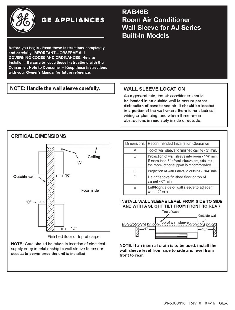
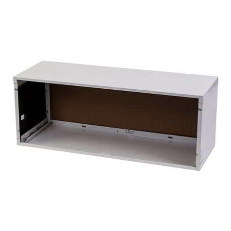
GE RAB46B User manual

GE

GE RAB46B User manual

GE RAKUVC1 User manual

GE

GE RAKUVC1 User manual

GE RAB71B Standard User manual

GE

GE RAB71B Standard User manual

GE 49218 Manual

GE

GE 49218 Manual

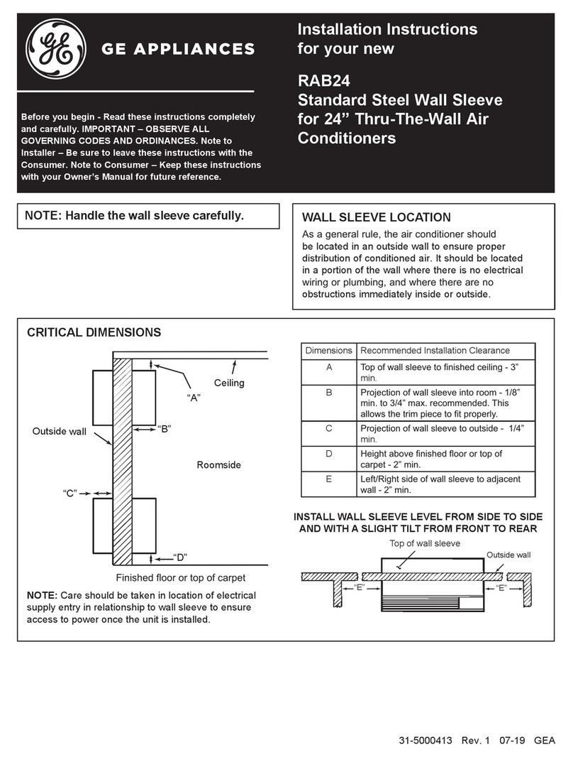
GE RAB24 User manual

GE

GE RAB24 User manual

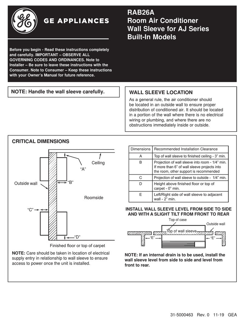
GE RAB26A User manual

GE

GE RAB26A User manual

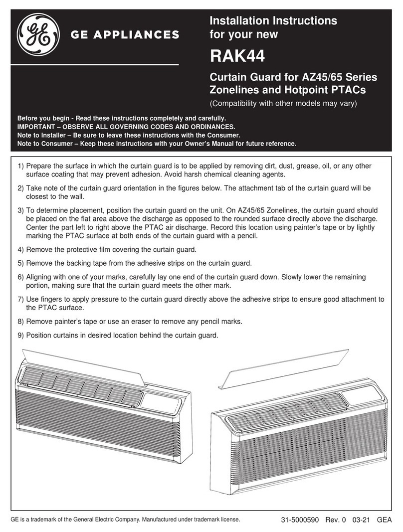
GE RAK44 User manual

GE

GE RAK44 User manual

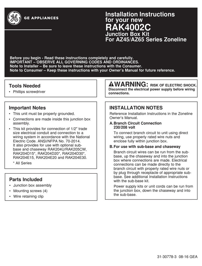
GE RAK4002C User manual

GE

GE RAK4002C User manual

GE RAB-71 User manual

GE

GE RAB-71 User manual

GE RAG60 User manual

GE

GE RAG60 User manual

GE RAK204U User manual

GE

GE RAK204U User manual

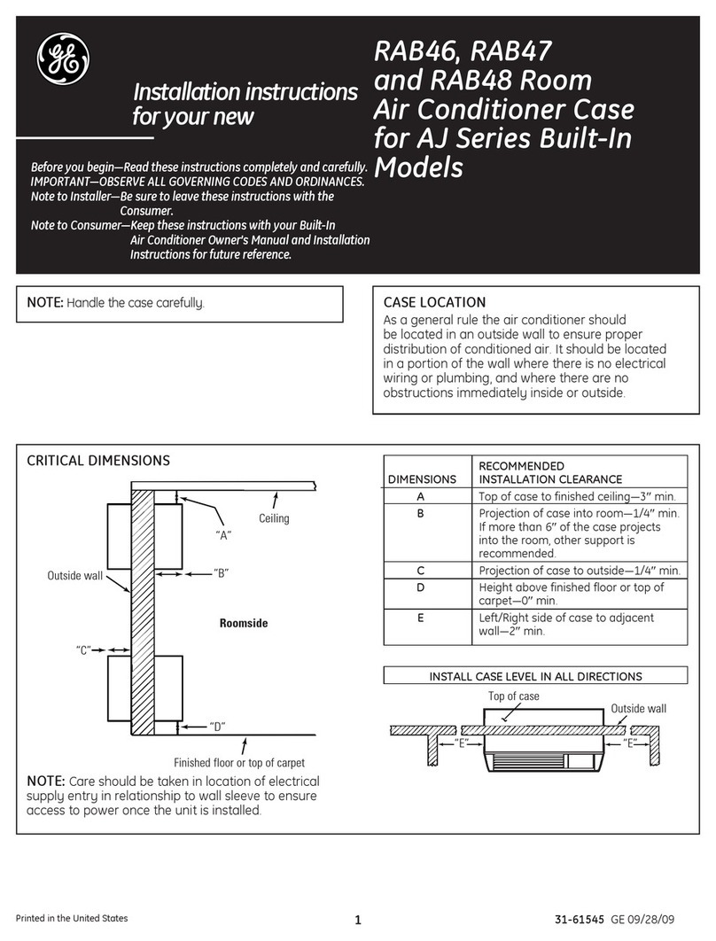
GE RAB46 User manual

GE

GE RAB46 User manual

GE RAB81 User manual

GE

GE RAB81 User manual

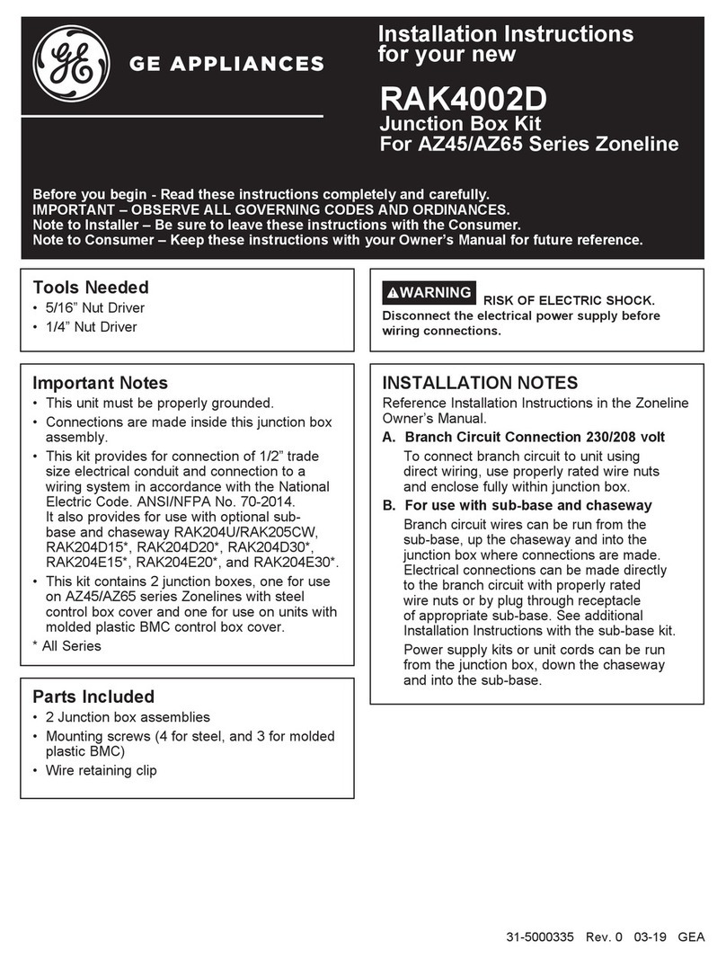
GE RAK4002D User manual

GE

GE RAK4002D User manual

Popular Air Conditioner Accessories manuals by other brands

Mitsubishi Electric PAC-SNH11HS-E installation manual

Mitsubishi Electric

Mitsubishi Electric PAC-SNH11HS-E installation manual

Unitary products group 2CE Series installation instructions

Unitary products group

Unitary products group 2CE Series installation instructions

Qlima EU-ODZ104 user manual

Qlima

Qlima EU-ODZ104 user manual

Tecnosystemi smart clima SCD500163 user manual

Tecnosystemi

Tecnosystemi smart clima SCD500163 user manual

Waeco AirCon Service Center ASC 5300 G operating manual

Waeco

Waeco AirCon Service Center ASC 5300 G operating manual

American Standard BAYSQRD001AA Installer's guide

American Standard

American Standard BAYSQRD001AA Installer's guide

Bimar AP11 Instruction booklet

Bimar

Bimar AP11 Instruction booklet

Mitsubishi PAC-SJ41TM-E installation manual

Mitsubishi

Mitsubishi PAC-SJ41TM-E installation manual

Tecnosystemi Smart Clima SCD500084 user manual

Tecnosystemi

Tecnosystemi Smart Clima SCD500084 user manual

Samsung MIM-H04U User & installation manual

Samsung

Samsung MIM-H04U User & installation manual

Waeco AirConServiceCenter ASC 3500 G LE operating manual

Waeco

Waeco AirConServiceCenter ASC 3500 G LE operating manual

Fujitsu UTZ-KXGC installation manual

Fujitsu

Fujitsu UTZ-KXGC installation manual

Hitachi E-52XN installation manual

Hitachi

Hitachi E-52XN installation manual

ActronAir LR7-1W Operation manual

ActronAir

ActronAir LR7-1W Operation manual

EMI 550000565 installation instructions

EMI

EMI 550000565 installation instructions

Tecnosystemi ARIA 2 ELEGANCE CR user manual

Tecnosystemi

Tecnosystemi ARIA 2 ELEGANCE CR user manual

RRS Jade XRD-01RDHAM3 Series Installation instruction

RRS

RRS Jade XRD-01RDHAM3 Series Installation instruction

Galletti estro UTN PWN quick start guide

Galletti

Galletti estro UTN PWN quick start guide

manuals.online logo
manuals.online logoBrands
  • About & Mission
  • Contact us
  • Privacy Policy
  • Terms and Conditions

Copyright 2025 Manuals.Online. All Rights Reserved.

31-5000414 Rev. 0 06-20 GEA
Installation Instructions
for your new
Before you begin - Read these instructions
completely and carefully.
IMPORTANT – OBSERVE ALL GOVERNING
CODES AND ORDINANCES.
Note to Installer – Be sure to leave these
instructions with the Consumer.
Note to Consumer – Keep these instructions
with your Owner’s Manual for future reference.
RAD10
For Installation on an
RAB71* (Steel), or RAB80* (Steel),
RAB81* (Steel), RAB77* (Molded),
RAB26* (Steel), or RAB46B* (Steel), RAB78B*
(Molded) Wall Sleeve, or RAB24* (Steel)
*all versions
NOTE: Parts in this kit will allow for two different types of installations onto the wall sleeve (external or internal.) A
combination of different parts is required. Depending on the type of installation selected, there may be some extra parts.
Parts Included
To Install the External Drain
The External Drain Kit is installed on the Zoneline Sleeve
if it desired to direct the sleeve overflow water to the
exterior and completely away from the installation.
1. The gasket should be placed on the cover plate (with
1/2” hole) with screw holes in the gasket lined up with
screw holes in cover plate. Then insert drain tube
(from gasket side) through gasket and cover plate (see
Fig. 1).
2. This assembly may now be installed into either the
left or right drain holes on the rear flange of the
sleeve, using two (2) of the screws (Type A for Metal
cabinet or Type B for Molded) included.
NOTE: The drain kit may be installed on the sleeve either
before or after the sleeve is installed in the wall, and
with or without the rear protective cover installed on the
sleeve. The stamped rear grille must be removed or the
drain kit installation made before the grille is installed. The
installation of the drain kit may be made from the outside
(rear of sleeve) or from the roomside (inside) by removing
the rear protective cover or rear grille.
To Install the External Drain (cont.)
3. The solid gasket (without hole) should be properly
placed on the rear of the solid cover plate and the
assembly installed over the drain hole in the sleeve
that it is not used to drain. Using two (2) of the
screws included (Type A or B depending on the type
of sleeve, attach to cabinet (see Fig. 2).
4. A tube or hose 1/2” I. D. (obtained locally) may be
installed onto the drain tube to drain any overflow
water away from the installation (to a gutter ot the
ground).
NOTE: To redirect the drain tube to another direction
(toward the side, downward, etc.) merely loosen the two
screws, rotate the drain tube to the desired direction
and retighten the screws.
CAUTION DO NOT point the drain tube above
the horizontal position.
2YHUÀRZUHOLHIGUDLQ
6TXDUHGUDLQKROHV
1HRSUHQHIRDPJDVNHW
6WHHOPRXQWLQJSODWH ´2'GUDLQWXEH
$OWHUQDWH
´ORQJ´2'
VWUDLJKWFRSSHUWXEH
)LJ +H[+HDGVFUHZV
Enter screw
through the back
of mounting plate Gasket
Drain Tube
Fig. 1
3” x 1/2” Straight
Tube
(1)
Drain Tube
(1)
Neoprene
Foam Gasket
(3)
Hex Head Screw
for external drains
(4)
Pan Head Screw
for internal drains
(2)
Nut
(2)
Steel Mounting
Plate (2)
Steel Mounting
Plate
(1)
2
Installation Instructions
Install the Internal Drain
Location of the Drain in the Cabinet Bottom
1. The Drain Kit must be installed on the bottom of
the wall sleeve prior to installation of the sleeve in
the wall. The location should not be in the area of
chassis supports or molded ribs (molded sleeve
only).
NOTE: If installation in the wall requires the use of a
sub-base, the location of the drain should be at least
3” from the front edge of the wall sleeve.
2. After location of Drain Kit is determined, locate and
drill 3 holes per dimensions on Fig. 3. The steel
mounting plate with the 1/2” center hole can also be
used as a template to mark holes. Repaint edges
of drilled holes on metal cabinet to prevent rust or
corrosion.
11/16”
1-3/8”
1/2” Diameter
3/32”
5/32” Diameter
(2 holes)
3. The gasket should be placed on the steel mounting
plate (with 1/2” hole) with screw holes in gasket
lined up with screw holes in steel mounting plate.
Then insert drain tube through gasket and steel
mounting plate, as shown in Fig. 4.
Nuts
Gasket
Sleeve bottom
Tube
” O.D.
Steel mounting plate
Pan Head screws
Fig. 4
Screw “A”
for metal
sleeves
Screw “B”
for molded
sleeves
Install the Internal Drain (cont.)
4. Attach this assembly to bottom of the wall sleeve
with two Type A screws through the cover plate,
gasket, and wall sleeve. On molded sleeve, the 2
speed nuts must be used to secure drain kit wall
sleeve using the two Type A screws.
5. Seal external drain holes. Prepare the remaining
mounting plates/gasket assemblies as shown in Fig.
2. Using the screws (Type A for Steel or Type B for
Molded sleeve) attach plate/gasket assemblies to
the bottom exterior flange over both as shown.
6. Install the wall sleeve into the wall opening (level in
all directions) and secure with adequate fasteners
per instructions packed with the wall sleeve.
7. A tube or hose 1/2” I.D. (obtained locally) must be
installed on the drain and connected to the internal
drain system in the building.
Fig. 3