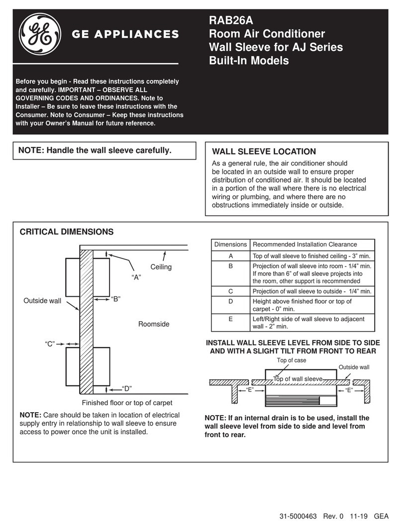
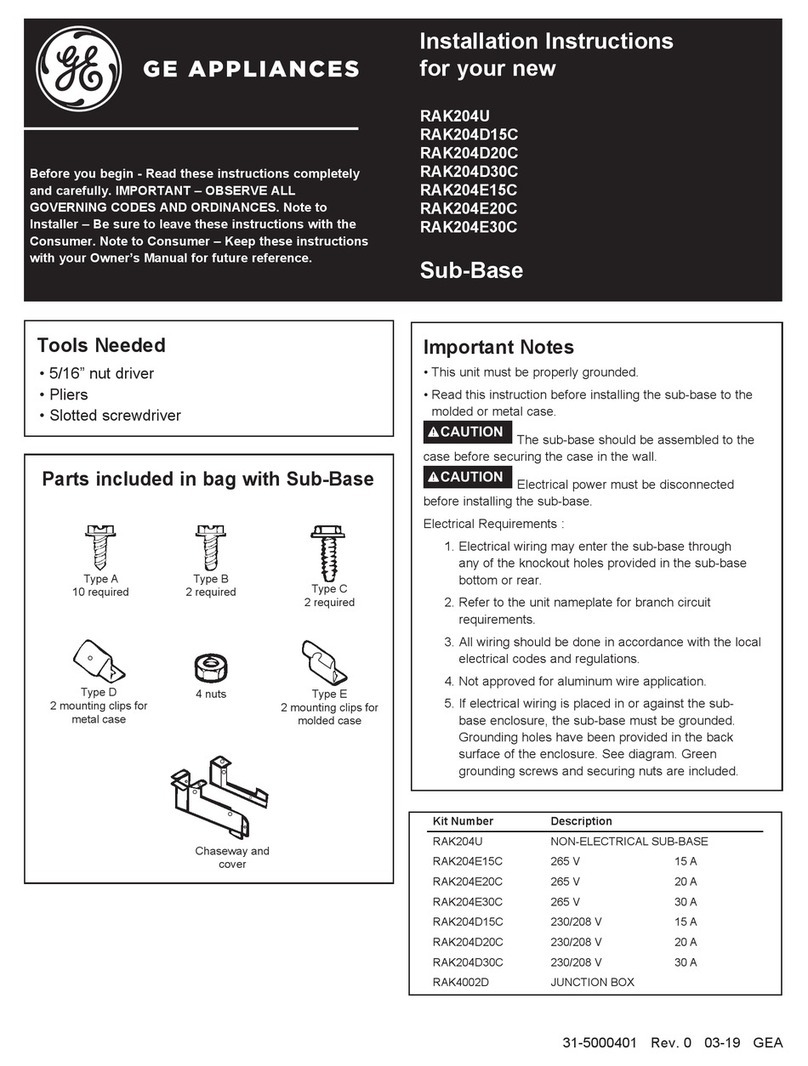
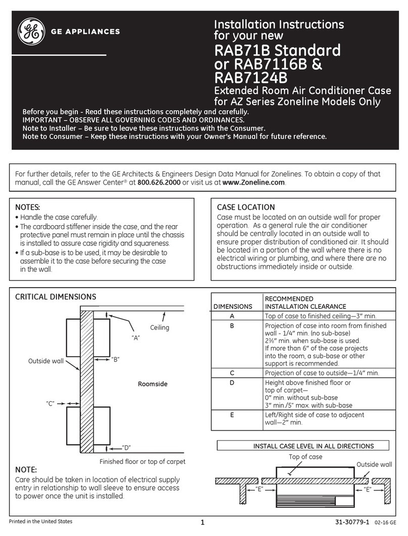
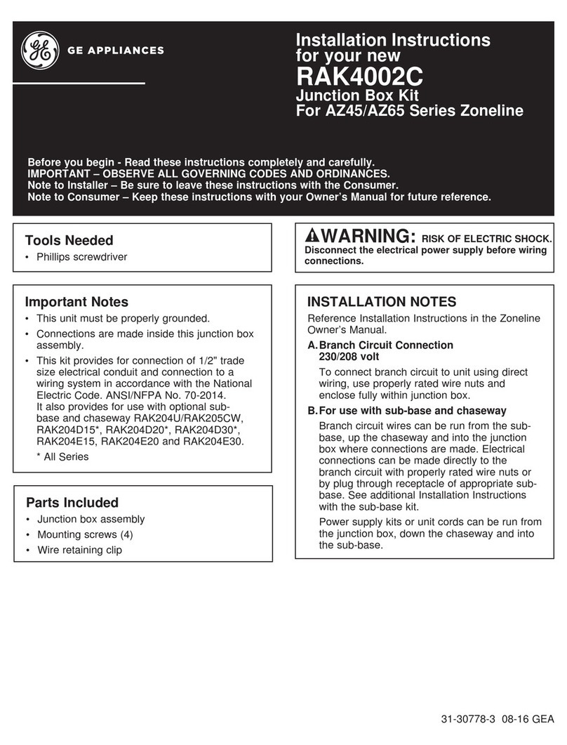
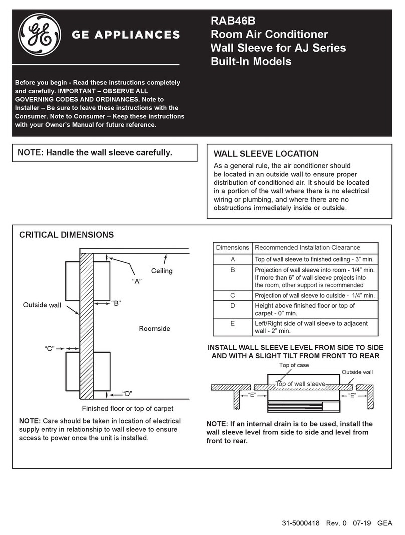
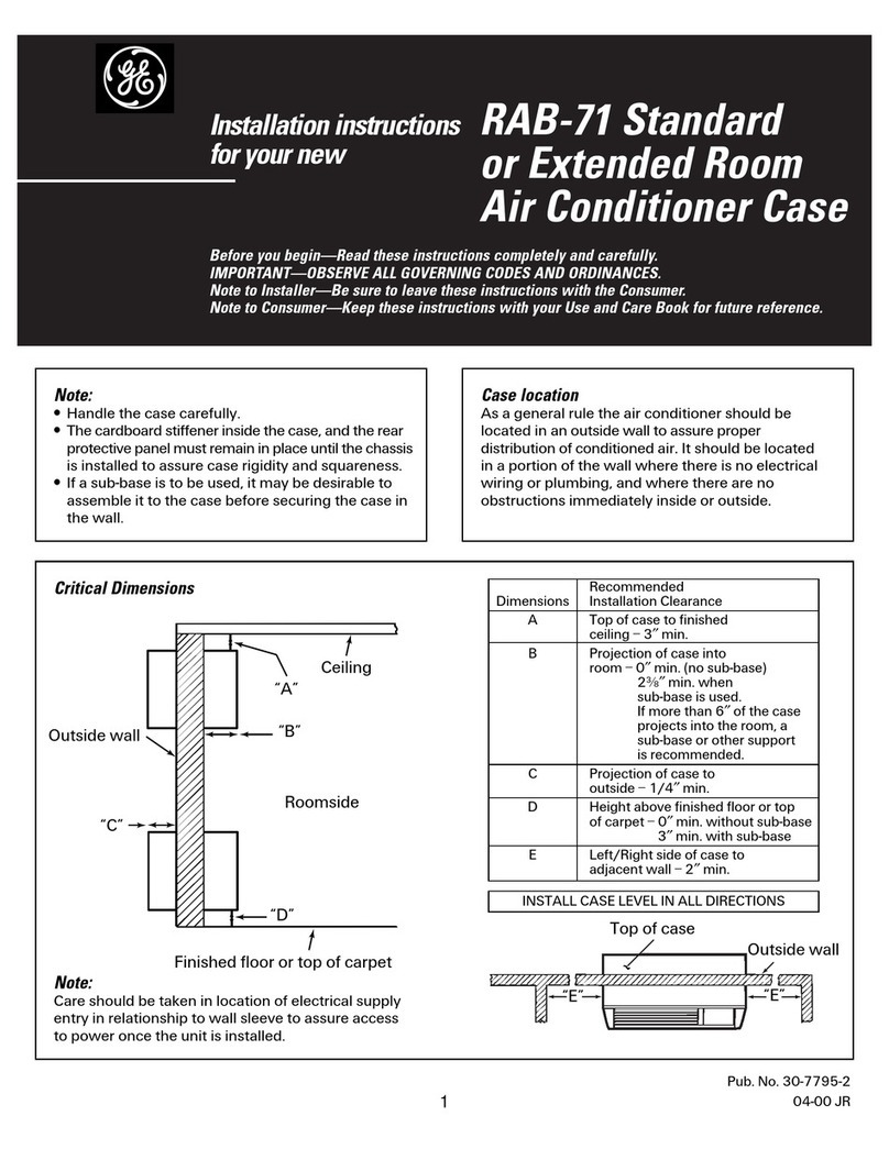
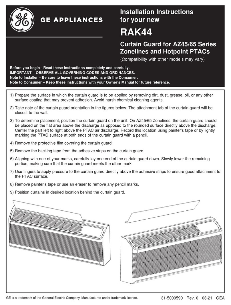
GE RAK4002D User manual

31-5000335 Rev. 0 03-19 GEA
Installation Instructions
for your new
Before you begin - Read these instructions completely and carefully.
IMPORTANT – OBSERVE ALL GOVERNING CODES AND ORDINANCES.
Note to Installer – Be sure to leave these instructions with the Consumer.
Note to Consumer – Keep these instructions with your Owner’s Manual for future reference.
RAK4002D
Junction Box Kit
For AZ45/AZ65 Series Zoneline
WARNING RISK OF ELECTRIC SHOCK.
Disconnect the electrical power supply before
wiring connections.
Tools Needed
• 5/16” Nut Driver
• 1/4” Nut Driver
Parts Included
• 2 Junction box assemblies
• Mounting screws (4 for steel, and 3 for molded
plastic BMC)
• Wire retaining clip
Important Notes
• This unit must be properly grounded.
• Connections are made inside this junction box
assembly.
• This kit provides for connection of 1/2” trade
size electrical conduit and connection to a
wiring system in accordance with the National
Electric Code. ANSI/NFPA No. 70-2014.
It also provides for use with optional sub-
base and chaseway RAK204U/RAK205CW,
RAK204D15*, RAK204D20*, RAK204D30*,
RAK204E15*, RAK204E20*, and RAK204E30*.
• This kit contains 2 junction boxes, one for use
on AZ45/AZ65 series Zonelines with steel
control box cover and one for use on units with
molded plastic BMC control box cover.
* All Series
INSTALLATION NOTES
Reference Installation Instructions in the Zoneline
Owner’s Manual.
A. Branch Circuit Connection 230/208 volt
To connect branch circuit to unit using
direct wiring, use properly rated wire nuts
and enclose fully within junction box.
B. For use with sub-base and chaseway
Branch circuit wires can be run from the
sub-base, up the chaseway and into the
junction box where connections are made.
Electrical connections can be made directly
to the branch circuit with properly rated
wire nuts or by plug through receptacle
of appropriate sub-base. See additional
Installation Instructions with the sub-base kit.
Power supply kits or unit cords can be run
from the junction box, down the chaseway
and into the sub-base.

2
2C. ATTACH WIRING USING A SUB-BASE
AND CHASEWAY (sold separately)
1. Remove the rectangular knockout at the bottom
of the junction box. Remove the rectangular
knockout at the right end of the sub-base.
2. Wiring is placed between the two halves of
the chaseway. Observe the orientation of the
chaseway.
3. Align the screw holes and secure the halves
together using two screws provided with
chaseway.
4.
Slide the upper end of chaseway with wiring protruding
into rectangular knockout opening in the junction box.
Be sure chaseway side flanges are on the inside of
the box. Drive one screw (provided with chaseway)
through the junction box bottom into the chaseway side
flange. Insert lower end of chaseway into rectangular
hole in sub-base and slide to right into the rectangular
knockout making sure chaseway side flanges are inside
the sub-base. Route wire toward the center of the
sub-base. Drive one screw (provided with sub-base/
chaseway kit) through the sub-base slotted hole into
chaseway side flange hole.
ZONELINE SERIES – DIRECT ELECTRICAL CONNECTION
Installation Instructions
STEP 1A. ALL MODELS
Remove the room cabinet by pulling it out at the bottom
to release it (1); then lift it up to clear the rail along the
unit top (2).
STEP 1B.
Check the control box cover on the front of the
Zoneline, just below the unit controls.
• If steel, use junction box labeled RAK4002C.
Proceed to step 2.
• If molded plastic BMC, use junction box labeled
RAK4002D. Proceed to step 3.
2A. JUNCTION BOX KNOCKOUT
For conduit installation: Use the round hole in the
bottom of the junction box base. Proceed to Step 2B.
For sub-base/chaseway installation: Remove
rectangular knockout from junction box base.
Proceed to Step 2C.
Round
Conduit
Knockout
Rectangular
Chaseway
Knockout
Mount wire
retaining
clip through
this hole
STEP 2: ZONELINE MODELS WITH STEEL CONTROL BOX COVER
2B. ATTACH WIRING USING A
CONDUIT
1. Use the round hole at the bottom of the junction box to
attach conduit coming from the branch circuit. Attach
the conduit using proper conduit connector and bring
wires into the junction box. Leave 6” of wire free at the
end of the conduit to allow connections to be made.
2. If a fuse and fuse holder are to be used, the
knockout at the side of the box is for mounting
a Buss Fuse holder. Be sure the fuse and fuse
holder are of the same rating as the branch circuit.
Leadwires at the fuse can be either soldered in
place or attached using UL-listed 1/4” female
(receptacle) crimp connectors.
Conduit
Knockout
Sub-base
Wiring
Chaseway cover
Chaseway

3
2F.
INSTALL JUNCTION BOX COVER
1. Carefully tuck all wires and connections back
inside the junction box. Be sure there are no
loose connections or stray uninsulated wires
exposed.
2. Align junction box cover ensuring mating tabs
base are inserted into slots on cover. Drive
screw securing cover in place.
3. Check to ensure all wires are inside junction box
and no wires are pinched between cover and
base.
4. Turn power back on to the installed unit and
check operation.
5. Replace the Zoneline front cabinet.
DIRECT ELECTRICAL CONNECTION
Installation Instructions
2D. INSTALL JUNCTION BOX
Install the junction box by inserting the left tabs
into control box cover slots, and aligning two screw
holes inside the upper and lower enclosure.
Tabs on
Junction
Box
Slots on
Control
Box Cover
Drive the two screws until they are secure.
Screws
Steel
2E. CONNECT THE POWER SUPPLY KIT
Plug the power connectors, ensuring plug is fully seated
and locking tabs are engaged.
15A 20A and 30A
For 20 AMP and 30 AMP power supply kits, a
second smaller plug must also be plugged into its
corresponding mating connector.

4
3C. ATTACH WIRING USING A SUB-BASE
AND CHASEWAY (sold separately)
1. Remove the rectangular knockout at the bottom of
the junction box. Remove the rectangular knockout
at the right end of the sub-base.
2. Wiring is placed between the two halves of
the chaseway. Observe the orientation of the
chaseway.
3. Align the screw holes and secure the halves
together by using a Type A screw in the lower or
longer section of the chaseway. The top screw
must be inserted in the next step.
4.
Slide the upper end of chaseway with wiring protruding
into rectangular knockout opening in the junction box.
Be sure chaseway side flanges are on the inside of the
box. Drive one screw (provided with chaseway) through
the junction box bottom into the chaseway side flange*.
Insert lower end of chaseway into rectangular hole in
sub-base and slide to right into the rectangular knockout
making sure chaseway side flanges are inside the sub-
base. Route wire toward the center of the sub-base.
Drive one screw (provided with sub-base/chaseway kit)
through the sub-base slotted hole into chaseway side
flange hole.
* Align the upper screw holes and use a Type A screw to
complete the chaseway assembly.
Installation Instructions
3A. SELECT ELECTRICAL
CONNECTION METHOD
• For Conduit Installation: Use the hole in the bottom
of the junction box to connect flexible conduit. Hole
is designed for 1/2” connector. Proceed to Step 3B.
• For Sub-Base Installation: Remove the rectangular
knockout in the bottom of the junction box base to
accept the chaseway from the sub-base. Proceed to
Step 3C.
STEP 3: INSTALL JUNCTION BOX ON MOLDED PLASTIC BMC
CONTROL BOX COVER
Screw
Tab
Junction Box
Base
Rectangular
knockout
3B. ATTACH WIRING USING A
CONDUIT
1. Use the round hole at the bottom of the junction box to
attach conduit coming from the branch circuit. Attach
the conduit using proper conduit connector and bring
wires into the junction box. Leave 6” of wire free at the
end of the conduit to allow connections to be made.
2. If a fuse and fuse holder are to be used, the
knockout at the side of the box is for mounting
a Buss Fuse holder. Be sure the fuse and fuse
holder are of the same rating as the branch circuit.
Leadwires at the fuse can be either soldered in
place or attached using UL-listed 1/4” female
(receptacle) crimp connectors.
Conduit
Knockout
Sub-base
Wiring
Chaseway cover
Chaseway
Ground wire

5
Installation Instructions
3G.
INSTALL JUNCTION BOX COVER
1. Carefully tuck all wires and connections back
inside the junction box. Be sure there are no
loose connections or stray uninsulated wires
exposed.
2. Install junction box cover by rotating the cover to
the right to locate the rear slots onto the mating
tabs on the rear of the junction box base. Rotate
back left to align the screw holes on the front
and install he screw.
3. Check to ensure all wires are inside junction box
and no wires are pinched between cover and
base.
4. Turn power back on to the installed unit and
check operation.
5. Replace the Zoneline front cabinet.
ZONELINE SERIES – DIRECT ELECTRICAL CONNECTION
3E. ATTACH JUNCTION BOX
GROUND WIRE
It is critical to attach the junction box ground wire to
the end sheet of the indoor coil. If the end sheet only
has two holes with attached ground wires, remove
the LOWER ground wire, add the loose end of the
junction box ground wire and attach both wires to the
end sheet using the same screw.
On some models, there will be an empty screw hole
between the two attached ground wires. On these
models, attach the loose end of the junction box
ground wire to this empty hole using the included
green fine threaded screw.
3D.
• Install the junction box base by inserting the upper
and lower tabs into the upper and lower slots on the
molded control box cover.
• Use provided 5/16” double helix screw to fasten
the tab on the top of the junction box base to the
molded front control box cover.
Lower
Slots
Upper
Slots
Screw
Boss
Molded Plastic Cover
3F. CONNECT THE POWER
SUPPLY KIT
Plug the power connectors, ensuring plug is fully
seated and locking tabs are engaged.
15A 20A and 30A
For 20 AMP and 30 AMP power supply kits, a
second smaller plug must also be plugged into its
corresponding mating connector.
Ground wire
Table of contents
Languages:
Other GE Air Conditioner Accessories manuals
Popular Air Conditioner Accessories manuals by other brands

Mitsubishi Electric
Mitsubishi Electric PAC-SNH11HS-E installation manual

Unitary products group
Unitary products group 2CE Series installation instructions

Qlima
Qlima EU-ODZ104 user manual

Tecnosystemi
Tecnosystemi smart clima SCD500163 user manual

Waeco
Waeco AirCon Service Center ASC 5300 G operating manual

American Standard
American Standard BAYSQRD001AA Installer's guide

Bimar
Bimar AP11 Instruction booklet

Mitsubishi
Mitsubishi PAC-SJ41TM-E installation manual

Tecnosystemi
Tecnosystemi Smart Clima SCD500084 user manual

Samsung
Samsung MIM-H04U User & installation manual

Waeco
Waeco AirConServiceCenter ASC 3500 G LE operating manual

Fujitsu
Fujitsu UTZ-KXGC installation manual