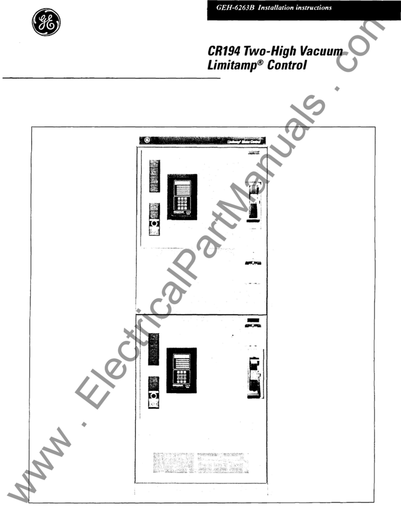
CR194Two-High VacuumLimitamp@Control
General
The basic CR194 two-high vacuum Limitamp@ control-
ler is a front connected assembly of components and
conductors for motor starting, arranged in a conve-
nient two-high vertical stack. The enclosure allows
space and facilities for motor cable termination, plus
safety interlocking of doors and isolation switch to pre-
vent inadvertent entrance to high-voltage parts. Unless
specified otherwise, the motor cable barriers are in-
stalled for bottom motor cable entry, but are easily
field converted from bottom to top or top to bottom
motor cable entry. Removable conduit cutout covers
are provided in both the top & bottom (if a bottom is
provided) for bringing in motor cable & control wir-
ing. In an effort to provide for maximum motor cable
access in the compact 36”-wide two-high design, in-
coming power cable must be connected in a separate
cable entrance compartment or the two-high must be
bus connected to existing equipment. No back access
is required, although both back and side access is pos-
sible by removal of back and side panels. The equip-
ment may be rated up to 5.0 kV.
In general, the starters in both the top and the bottom
are divided into high-voltage and low-voltage
compartments, separated by doors and barriers.
Mounted on the high-voltage door of each starter is
the low-voltage control cavity, with the low voltage
door hinged to the high-voltage door. Access to the
low voltage panel is obtained by rotating the two ‘/4
turn latches on the low-voltage door, then opening the
door to the left. To open the high-voltage door, the
power must be disconnected by a sequence of
manual operations which requires de-energizing the
high-voltage contactor, operating the isolation switch
handle by rotating it downward, loosening the two
latch bolts on the high-voltage door, then opening the
door to the left. Low-voltage doors may be entered
without disconnecting the power, but this should be
done with caution.
Installation, operation and maintenance should be
performed only by experienced personnel trained in
this class of equipment.
Ratings
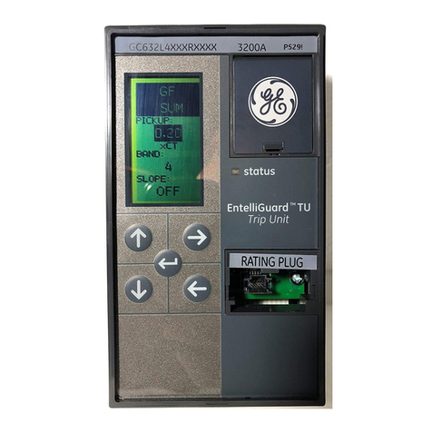
Refer to the panel data nameplate (see Figure 4) on
the front of the enclosure for detailed ratings appli-
cable to a particular controller. Equipment basic rat-
ings equal or exceed NEMA ICS 3, Part 2 for Class E2
Controllers, and are summarized below.
Starter Main Bus & Maximum Current Ratings
Starter
Max.
Main Bus
Current
lBar/ 1 2 Bars/ Top 1 Bottom
Enclosure Type
Phase Phase Unit
Unit
Vented 12OOA 2000A 360A 4OOA
Non-Vented 12OOA 195QA 320A 320A
Figure 4. Operating handle, handle operating instructions
and panel data nameplate
Interrupting Ratings At Utilization Voltage Shown
Three-phase Symmetrical
Maximum Sytem mVA
Maximum Continuous Class El Class E2
Volts Amperes(RMS) Unfused Fused
2500 400 25 200
3600 400 37 300
5000 400 50
4m
Basic Impulse Level (BIL)
The standard BIL rating of vacuum Limitamp@ con-
trollers is 60kV crest (design rating). This rating ex-
cludes dry-type control transformers and starting reac-
tors & autotransformers.
Dielectric Test Voltage
2% times nameplate voltage plus 2000 volts.
High-Voltage Vacuum Contactors
The vacuum contactors used in vacuum Limitamp@
controllers are available in two different ratings: 400
and 800 amperes. This publication covers only the 400
ampere rating as used in CR194 two-high vacuum
Limitamp@. The 400 ampere and 800 ampere
contactors are similar in operation but very different
5

