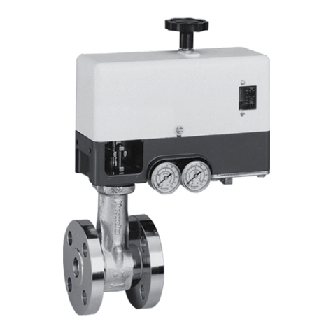
GE Becker 3.5M Series User manual

GE Oil & Gas
Becker*Digital Natural
Gas Positioner (DNGP)
Series 3.5M with Modbus™Protocol
Instruction Manual
Table of Contents
Sections Page
Introduction...........................................................................................2
Scope of Manual.................................................................................2
Technical Assistance .......................................................................2
Technical Specifications..................................................................4
Principle of Operation .....................................................................4
Wire Size Recommendations .......................................................4
Logic Board & Wiring Diagram ...................................................5
Jumpers & Fuses ...............................................................................5
Orifice Adjustment ............................................................................7
Pressure Control Override .......................................................... 10
Rotary Position Transmitter ....................................................... 14
Rotary Transmitter Calibration ................................................ 15
Linear Transmitter........................................................................... 16
Replacing Electronic Module.......................................................22
Linear Transmitter Programming ............................................23
High Pressure 5/3 Solenoid Valve ............................................24
High Pressure 5/3 Solenoid Valve Conversion and
Replacement .....................................................................................25
Sections Page
Low Pressure 2/2 Solenoid Valve..............................................26
High Pressure 3/2 Solenoid Valve.............................................26
3/2 and 2/2 Solenoid Valve Maintenance &
Troubleshooting................................................................................27
The Run-Time Screen .............................................................28-29
Input Configuration Menu ...........................................................30
Valve Actions Menu ........................................................................31
Logging & Alarms Menu ........................................................31-32
The Firmware Menu .......................................................................32
Upgrading the DNGP Firmware ................................................34
DNGP Leak Test Procedure .........................................................37
Certifications & Approvals............................................................38
Software Release Information....................................................38

2
Electrical Power Requirements
VIN = 12 to 24 VDC nominal (11-30 VDC) 21 VDC min. for 24 VDC Sole-
noid, 11 VDC min. for 12 VDC Solenoid 1 to 2 A including DNGP heater
and transmitter heater (3 A fuse line recommended)
Over Current Protection
20 Joule, 2000 A surge and lightning transient protection 3 A fuse for
Logic module 24 VDC power 50/150 mA PTC resettable fuses for posi-
tion input signal and transmitter feedback signal
Position Input Signal (Selectable) Standard 4-20 mA (Split Range: 4 mA min. up to 16 mA max. in 1 mA increments),
minimum 4 mA band
Transmitter Feedback Signal Analog Rotary: External or Internal Digital Linear: Internal only; RTU
Feedback must be dry
Remote Indicator Dual Function Output
Outputs VIN-1.5V @ 20 mA max. (for example if VIN = 24 VDC, this
supplies 22.5 ± 0.5 V)
The remote Indicator function can be selected to function as “Solenoid
Counter” or “In Standby/Manual”. In Counter mode it pulses whenever
either solenoid activates. In Standby/Manual mode, it is active
whenever the DNGP is in Standby or Manual modes.
Valve Position Feedback Module Primary: Linear Digital Transmitter Analog Rotary Types Also Available:
Display
80 (4 x 20) character Vacuum Fluorescent Display for: Command
Signal, Valve Position Feedback, Solenoid Cycle Count (stored in 10 year
non volatile memory), Dead Band value. Incorporates a user
navigational menu system.
Input Mode Selection Manual/Auto/Standby
Electrical Manual Override Manual pushbutton positioning (must engage Manual Mode with Auto/
Manual/Standby Switch)
Communications DNGP Dashboard PC Interface, Modbus™communication protocol
Solenoid Bypass Can be ON or OFF within 1.5% of the end stroke (in full closed and
open position).
Loss of Signal Options (Selectable) Drive to 4 mA position (open or closed valve position) Drive to 20 mA
position (open or closed valve position) Lock in last controlled position
Position Input Signal Impedance 120 to 220 Ω
Transmitter Feedback Input Signal Impedance transmitter) 120 to 220 Ω (additional operating voltage required for
Introduction
The DNGP is designed specifically for the needs of the
Natural Gas industry. By using solenoids to control the
actuator pressures, the DNGP eliminates the continuous
bleed gas produced by I/P transducers and bleeds no
gas until the valve is called upon to move. The DNGP
can even do this while maintaining a pressure difference
across the actuator. Additionally, the discharge can
be directed downstream, and the positioner is capable
of failing in last position on a loss of signal, DC power
or power gas. Reliability and simplicity have been
engineered into the DNGP, while features that make the
positioner versatile, easy to use, and fail safe, have been
retained.
Scope of Manual
This manual provides information on the installation,
adjustment, and maintenance of the DNGP-Digital
Natural Gas Positioner. For information concerning
actuators, valves, and accessories, refer to the
instruction manuals provided with the specific product.
Technical Assistance
Only those qualified through training or experience
should install, operate, or maintain Becker position-
ers. Should you have any questions concerning these
instructions, you may contact your local GE sales
representative, sales office, or manufacturer before
proceeding.
GE Energy
Becker Control Valves
Attn: Technical Assistance
1550 Greenleaf Avenue
Elk Grove Village, IL 60007
Toll Free: +1-800-323-8844
Telephone: +1-847-437-5940
Fax: +1-847-437-2549
web: ge.com/energy
Table 1 - DNGP Technical Specifications
3
Table 1 - DNGP Technical Specifications (continued)
Input Signal Action Direct or Reverse Acting (selectable by accessing DNGP Menu and
Transmitter Switch)
Pneumatic Action Double Acting or Single Acting
Deadband Adjustable from 0.1% to 2.0% of full travel
Hysteresis <2.0% full scale (with rotary position feedback transmitter
Linearity <±1.0% full scale (with standard linear digital transmitter)
Repeatability <±1.0% full scale (with standard linear digital transmitter)
Operating Temperature -20 ºF to 150 ºF (-29 ºC to 66 ºC)
Influence of Temperature on Valve Position <0.01% per ºF (<0.02% per ºC)
Steady State Gas Consumption ZERO - see Table 2.0 for additional information
Recommended Supply Regulator Capacity
100 SCFM at 250 psig (1724 kPa) - Natural Gas
45 SCFM at 100 psig (689 kPa) - Natural Gas
30 SCFM at 60 psig (414 kPa) - Natural Gas
Electrical Classifications
Electrical Enclosure Explosion Proof for Class I Groups C and D
;Class II Groups E, F, G; Class III hazardous locations
CSA approved, RoHS compliant
Optional ATEX available
Enclosure Available in explosion proof housing with window or NEMA-4 Poly
carbonate enclosure for remote control board mounting
Approximate Weight 15 lb. (5.6 kg); includes standard explosion proof DNGP enclosure and
High Pressure 5/3 Solenoid Valve.
Valve Position Limit Switches
Low limit settable from 0 to 45% closed
High limit settable from 55 to 100% of open
Contacts ratings (maximum)
Power: 180 W or 1800 VA
Current: 6A
Voltage: 150 VDC or 300 VAC
(UL 6 A @ 28 DC, VDE 5 A @ 250 VAC).
Digital Control Inputs
Low limit settable from 0 to 45% closed
High limit settable from 55 to 100% of open
Contacts ratings (maximum)
Power: 180 W or 1800 VA
Current: 6A
Voltage: 150 VDC or 300 VAC
(UL 6 A @ 28 VDC, VDE 5 A @ 250 VAC).
Digital Control Inputs
12 to 24 V nominal (11 to 30 V).
Digital input current: 3.5 mA at 24 V
One input controls Open, one input controls Close, and common Open/
Close return signal.
Maximum Power Supply Gas
Pressure
250 psig (1724 kPa) with 5/3 type DNGP Solenoid Valve
(Check Maximum Actuator Power Supply Pressure Limitations)
150 psig (1034 kPa) with 3/2 type DNGP Solenoid Valve
(Check Maximum Actuator Power Supply Pressure Limitations)
Pneumatic Port Connection 1/4” FNPT standard, larger sizes available for additional capacity
Electrical Conduit Connections 3/4” FNPT standard

4
Principle of Operation
The solenoid operated electro-pneumatic positioner
compares a 4-20 mA signal from a RTU to a 4-20 mA
signal from a position transmitter. Depending upon the
difference between the two signals, the positioner will
energize the open or close solenoid to drive the control
valve toward the desired position. If the signals are
within an adjustable dead band, neither solenoid will be
energized. The solenoid tubing is connected to the valve
actuator through a variable orifice. This orifice allows the
valve speed to be increased or decreased. The faster the
valve speed, the larger the positioner dead band must
be to prevent overshoot of the valve position. When the
input signal falls within 1.5% of either full open or full
closed, and bypass enable is selected, the positioner will
continually energize the appropriate solenoid to provide a
full pressure differential across the cylinder.
Explosion Proof
Enclosure with
Window
5/3 High Pressure
Solenoid Valve
Figure 1 - DNGP EXP Enclosure and High Pressure 5/3 Solenoid Valve
Wire Size Recommendations
Wires of insufficient size will create a voltage drop
between the power supply in the control room and the
DNGP at the valve site. This voltage drop is created by
resistance in the wire carrying power to the DNGP. Smaller
diameter wires have more resistance than larger wires
and therefore produce a larger voltage drop. Resistance is
also function of the length of the wire. From this informa-
tion, the equation needed to figure the proper wire size is
governed by equation (1):
(1) VDROP = (2*L*I*R)/1000
Where:
VDROP (Volts) = Voltage drop between the power supply
and DNGP
L (Ft.) = Length of wire (one way) between power supply
and DNGP
R (Ohm) = Resistance per 1000 ft. of the wire
I (amps.) = DNGP current draw = 1 A
Equation (1) tells us that for longer distances of wire
between the power supply and the DNGP, larger sizes of
wire are required to keep the voltage drop to a minimum.
Voltage drops greater than 4 Volts are not recommended
for proper use of the DNGP. The user should note that
wire size increases as the gauge of wire decreases. Refer
to table 2.0 for all pertinent voltage information.
Table 2 - Wire Size, Wire Resistance, and Voltage Drop Information 1,2,3,4
In the case of single acting actuators, the pressure will
be full power gas pressure or zero psig. If either the
RTU signal or transmitter signal falls below 3.5 mA, the
positioner will enter failure mode. In failure mode the
positioner will move the valve to fully open, fully close, or
hold the current position depending on the user specified
failure configuration.
Wire Size Resistance per 1000 ft Length of Wire (one way) for 4 Volts Drop
18 AWG 8.45 Ohms 240 Feet
16 AWG 5.29 Ohms 380 Feet
14 AWG 3.26 Ohms 610 Feet
12 AWG 2.05 Ohms 980 Feet
10 AWG 1.29 Ohms 1550 Feet
1 - Check with wire manufacturer for more accurate resistance data.
2 - Adding multiple DNGP’s to a single pair of power wires will increase the voltage drop proportionally.
3 - Voltage drops greater than 4 volts are not recommended.
4 - Actual resistance of wire may differ based on wire characteristics and manufacturer.

5
Logic Board & Wiring Diagram
The DNGP is equipped with two terminal boards. Terminal
board #1 has 10 connections and terminal board #2
has 14 connections. Terminal board #2’s connections
are associated with the main user interface signals (limit
switches, power inputs, position feedback inputs, etc.),
while terminal board #1 applies to other interface signals
(transmitter position inputs, solenoid inputs, heaters, etc.).
A complete logic board layout, and wiring guide for both
terminals is given on pages 6 and 7 respectively.
Jumpers & Fuses
A look at the logic board layout on page 7 shows the
location of the jumpers JP1 and JP2. The selection of the
jumpers depends on the power of the transmitter. If the
transmitter doesn’t need external power, select JP1 - 1,
2. If the transmitter needs external power, select JP1 - 2,
3, or remove the jumper. The jumper JP2 functions only
as a spare replacement for JP1. There are 4 fuses on the
DNGP logic board. The first fuse F1 is 0.1 Amperes, and
serves as the PTC fuse for a 4-20 mA signal current loop.
F2 is 0.1 Amperes, and serves as the PTC fuse for a 4-20
mA transmitter/ positioner current loop. The fuses F1 and
F2 are resettable. F3 is a 3 Ampere fuse for the voltage
input power. Finally, F4 is a 3 ampere replacement fuse
for F3.
Figure 2 - Terminal Board #1 (10 Pins) & Terminal Board #2 (14 Pins)
Note 1: Check RTU manual for correct polarity before connecting to terminal.
Note 2: Jumper must be installed between pins 5 & 6 if feedback is not connected.

6
Figure 3 - DNGP Logic Board Layout
Jumper between Pins 5 & 6 on
Terminal Board #2 (Only used if
RTU feedback is not connected)
Terminal Board #1
(10 Connectors)
Pin #1
Pin #10
Pin #14
F1 - 0.1 A, PTC Fuse
for 4-20 mA Signal
Current Loop
Terminal Board #2
(14 Connectors)
JP2 - Jumper, Spare
Replacement for JP1
Manual Auto
Stand-by Switch
F2 - 0.1 A, PTC Fuse for
4-20 mA
Transmitter/Positioner
Current Loop
F3 - 3 A, Fuse VIN
Input Power
F3 - 3 A Spare
Replacement for F3
JP1
Jump 1-2 when Digital Linear
Transmitter is used; RTU feedback
loop power must be off)
JP1 for Analog Rotary Transmitter
Option 1: Jump 1 & 2 of JP1 in order to
power the loop from external source; RTU
provides the power
Option 2: Jump 2 & 3 of JP1 in order to
power the loop with DNGP’s internal power
source; RTU does not power the loop

7
Orifice Adjustment
Orifices at each of the cylinder ports (double acting) or
flow control valve (single-acting) control the flow of gas
into the actuator, and therefore, the speed at which the
valve moves.
Initially, both orifices should be set at maximum value. If
more precise valve positioning is required for the applica-
tion, decrease the orifice settings, one or two numbers at
a time, and readjust the sensitivity. Because the valve will
be moving slower, a smaller dead
Table 3 - Orifice Part Numbers
Figure 4 - Variable orifice assembly (standard assembly shown)
Assembly
(Orifice included)
Orifice
Figure 5 - For 2” & 3” valves an additional backpressure valve (metering valve) is used.
Orifice Size “Marking Part #
Standard
(No Mark)
Assembly 25-1559
Orifice Only 25-1040
Medium “M” Assembly 25-8162
Orifice Only 25-8075
Large “L” Assembly 25-8163
Orifice Only 25-8076

8
Figure 6 - 4” to 12” valves are used with “M” orifice blocks, 14” & 16” valves are used with “L” orifice blocks
Figure 7 - For valves > 16” no orifices are needed.

9
Figure 9 - Single Acting Control Valve, PSUPPLY ≤ 40 Psig
Figure 8 - Single Acting Control Valve, PSUPPLY ≥ 50 Psig

10
Electro-Pneumatic Positioner Pressure
Control Override*
Conventional flow control with PCO (Pressure Control
Override) is accomplished by sending a signal to the
positioner from an I/P transducer or pneumatic controller.
A HIGH SELECT RELAY determines if the positioner is
controlled by the pneumatic controller (pressure control)
or the I/P (flow control).
Figure 10 - Conventional Flow Control with Pressure Control Override (PCO)
By exchanging the I/P with an electro-pneumatic
positioner, the pneumatic positioner can be eliminated.
Using the DNGP for the electro-pneumatic positioner
allows the unit to fail open, closed, or in last position on
loss of 4-20 mA signal. Becker high pressure VRP pilots
and Becker high pressure HIGH/LOW selector relays
ideally complement the DNGP electro-pneumatic
positioner for high or low pressure override.
*For double acting systems, Becker double acting pilots are used. See the sampling
of pneumatic schematics for specific pressure control override applications on the
next two pages.
Figure 11 - Flow Control with Electro-Pneumatic Positioner and PCOH High Pressure Override
Signal Selector

11
Figure 12 - Double Acting Control Valve with PCO, PSUPPLY ≥ 50 Psig (High Pressure Override)
Figure 13 - Double Acting Control Valve with PCO, PSUPPLY > 50 Psig (Low Pressure Override)

12
Figure 14 - Single Acting Control Valve with PCO, PSUPPLY ≥ 40 Psia
Figure 15 - Single Acting Control Valve with PCO, PSUPPLY > 50 Psia

13
Figure 16 - Rotary Piston Spring To Close Actuator with High Pressure 3/2 solenoid valve PSUPPLY 40 - 150 psig
Figure 17 - Rotary Piston Spring To Open Actuator with Pressure Control Override, PSUPPLY 40 - 150 psig

14
Table 4 - Rotary Transmitter Technical Specifications
Heater Power 12 - 24 Volts DC
Operating Temperature
Range
-40 ºF to 185 ºF
Recommended Power Loop Power 4-20 mA
Output Signal Range 4 to 20 mA DC
Load Impedance 0-950 Ohms at 24 Volts DC
Output Current Limit Internally limited to 33 mA
Ambient Temperature For a 100 ºF change in ambient temperature,
the maximum zero shift is ±0.3% and the
maximum span shift is ±0.4% of span
Rotation Range 45º - 95º
Linearity ±1.0%
Hysteresis 1% of full scale
Repeatability ±0.3% of full scale
Figure 18 - Rotary Piston Spring Return Actuator with Snap Acting Selector Relay, PSUPPLY 40 - 150 psig
For Short Dynamic Systems such as Power Plants
Notes
1. Control valve will close on increasing measured variable pressure
2. Regulator is to open on loss of power gas
3. VRP-SB-PID and DNGP are non-bleeding in steady state, full open & full closed position
4. Control valve shown in full open position
DNGP with Rotary Position Transmitter (Standard)
The Rotary Position Monitor is used in conjunction with the DNGP. This polarity
independent, transient protected, transmitter can operate with any voltage
from 5 to 38 volts DC. CW and CCW rotation is easily accommodated as well
as long cable runs and multiple receivers. It has an easy set up, non-interactive
adjustment, and is available in 4-20 mA. For information on installation,
calibration, and wiring diagrams please refer to appendix A of this manual.
The rotary transmitter incorporates a 1/4% precision potentiometer
specifically design for DNGP positioner.
(149.3)
5.88”
(153.9)
6.06
*All Dimensions in [mm] in.
Figure 19 - Overall Dimensions of Rotary Transmitter

15
Rotary Transmitter 4-20 mA Calibration Procedure
1. Mount the rotary transmitter to the actuator. Set limit
switches if supplied per instructions provided with unit.
2. Connect a Loop Power source to terminal points
1 & 2. The multi-meter (set for mA readings) must be
connected in series with the terminal one (refer to unit
wiring diagram for the standard setup procedure)
3. Stroke the valve to fully clockwise extreme.
4. Depress the main shaft gear disengaging it from its
locking position, take extreme care Not to turn the
main shaft gear, in order to maintain proper switch
settings.
5. With main shaft gear depressed turn the transmitter
gear to the fully counterclockwise position, and
not the reading (mA) of transmitter. Next, turn the
transmitter gear clockwise until the transmitter
changes no more than 0.5 mA from previous reading.
Renegage gears (if equipped with mechanicals
witches, depress switch plunger to allow gear to
engage).
6. Turn the clockwise mA adjustment screw to adjust the
transmitter reading to the desired output for this valve
position (typically this is 4 mA or 20 mA).
7. Stroke the valve to the fully counter-clockwise
extreme.
8. Turn the counter-clockwise mA adjustment screw to
adjust the transmitter reading to the desired output for
this valve position (opposite of step 6).
9. Stroke the valve between the full clockwise and
counter-clockwise positions checking and readjusting
the (mA) output as necessary.
Figure 20 - Components of Rotary Transmitter or Calibration Procedure
Main Shift Gear
Transmitter Gear
Adjustment Screw 20mA
for close on increasing
Clockwise mA Adjustment
Screw 4 mA for close on
increasing

16
Figure 21- Rotary Transmitter Wiring Diagram
Jumper Settings for DNGP with
Rotary Transmitter
Option 1.
Jump 1 & 2 of JP1 in order to power the loop
from external source; RTU provides the power.
Option 2.
Jump 2 & 3 of JP1 in order to power the loop
with DNGP’s internal power source; RTU should
not power the loop.
DNGP with Linear Transmitter Assembly (Tail Rod & Standard Configurations)
A linear digital proximity transmitter will be used
whenever linear motion is available. These transmitters
offer high resolution with a non-contact proximity design.
The linear transmitter is available in a tail rod or standard
configuration. Figure 22 indicates the major components
in a typical tail rod configuration, while in Figure 24
the same concept is used to show the standard
configuration.
Figure 22 - DNGP and Linear Transmitter Tail Rod Configuration
Linear Transmitter
High Pressure 5/3
Solenoid Valve
DNGP inside Explosion
Proof Enclosure
Tail Rod
Cylinder Top

17
Table 5 - Tail Rod/Proportional Configuration Part Numbers
Item # Part # Description
1 98-3176 10-32 x 1” SHCS
2 98-2529 10-32 Hex Nut
3 31-2013 Bracket
4 98-2782 3/8” ID Lockwasher
5 98-2927 1/4-20 x 2” HHCS
6 98-3269 8-32 x 1/2” SHCS (Alloy)
7 01-8901 Magnet
8 98-3181 7/16 FT Washer (SS)
9 25-8145 Spacer
10 98-3281 7/16-20 x 3” HHCS
11 01-6592 Bushing
12 31-2014 Transmitter Block
1
2
3
4
5
7
6
9
12
11
10
8
Figure 23 - Detailed View of the Linear Position Transmitter Tail Rod Transducer

18
10
9
Table 6 - Riser Pipe Mount Configuration Part Numbers
Item # Part # Description
1 31-2005 Adjusting Bushing
2 98-2614 8-32 x 1/2 SHCS (316)
3 98-2538 8-32 Hex Nut (18.8)
4 31-2004 Adjustment Block Probe
5 01-8901 Magnet
6 98-2579 1/4-20 x 1 HHCS (18.8)
7 98-2777 1/4” Lock Washer
8 98-3171 8-32 x 1/2 SHCS
9 Reference
Table 7
Indicator Bar
10 98-2638 1/4-20 x 5/8 SHCS (18.8)
Cylinder Bar Part#
6” 14-3114
8” 14-3130
10” 14-3121
12’ 14-3068
NOTES:
1. Lock the screw (2) after any adjustments are completed.
2. Turn the magnet (5) with the adjustment bushing to align 4 or 20 mA.
Figure 24- Detailed View of the Linear Position Transmitter Standard Assembly
1
2
3
4
5
7
6
8
WARNING: This Model Was Discontinued in 2007
Table 8 - Reversible Fixed Range Linear Position Transmitter Specifications
Measured Parameter Specification Analog Output
Repeatability
(Resolution + Hysteresis)
Voltage-Output Versions 0.5 mV or 5 μm (whichever is greater)
Current-Output Versions 1 μA or 5 μm (whichever is greater)
Sampling Rate For stroke lengths ≤ 2000 mm 1 kHz
For stroke lengths > 2000 mm 500 Hz
Non-linearity For stroke lengths ≤ 500 mm ± 100 μm
For stroke lengths > 500 mm ± 0.02% of full-scale
Pressure Rating (Rod) Up to 600 bar
Operating Temperature -40°F to +185°F
Supply Voltage +24 VDC ± 20%
Humidity <90% non-condensing
Table 7 - Indicator Bar Part Numbers

19
Figure 24 - Linear Transmitter Overall Dimensions
Figure 25 - Linear Transmitter Adapter Flange Figure 26 - Linear Transmitter Magnet
WARNING: This model was discontinued in 2007
Figure 27 - Reversible Linear Transmitter Connector

20
Figure 28 - Linear Transmitter Wiring Diagram
Table 9 - Programmable Linear Position Transmitter Specifications (Supplied 2006 and later)
Measured Parameter Specification Analog Output
Repeatability
(Resolution + Hysteresis)
Voltage-Output Versions 0.5 mV or 5 μm (whichever is greater)
Current-Output Versions 1 μA or 5 μm (whichever is greater)
Sampling Rate For stroke lengths ≤ 2000 mm 1 kHz
For stroke lengths > 2000 mm 500 Hz
Non-linearity For stroke lengths ≤ 500 mm ± 100 μm
For stroke lengths > 500 mm ± 0.02% of full-scale
Pressure Rating (Rod) Up to 600 bar
Operating Temperature -40°F to +185°F
Supply Voltage +24 VDC ± 20%
Humidity <90% non-condensing
Table of contents
Other GE Control Unit manuals

GE
GE EX2100 User manual

GE
GE MiCOM P40 Agile User manual

GE
GE SX TRANSISTOR CONTROL IC3645SR4U404N2 User manual

GE
GE CompactPCI VMIACC-7055 Series User manual

GE
GE b30 User manual

GE
GE PACSystems RX3i IC695ETM001-JW User manual

GE
GE NetworX Series User manual

GE
GE VersaMax IC200CHS006 User manual

GE
GE Dialog User manual

GE
GE CR194 User manual