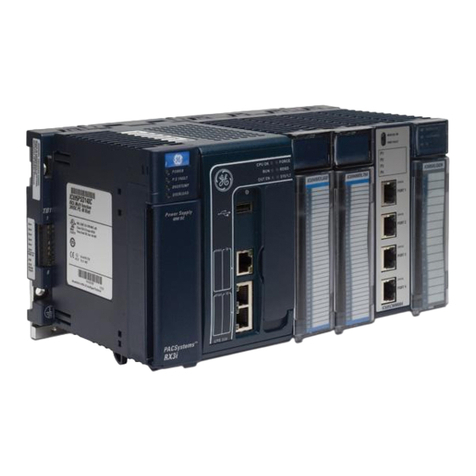
GE PACSystems RXi User manual

GE
Intelligent Platforms
g
Programmable Control Products
PACSystems* RXi
Distributed IO Controller
ICRXICTL000
User Manual
GFK-2816F
August 2015

Legal Information
Warnings, Cautions, and Notes as Used in this Publication
Warning
Warning notices are used in this publication to emphasize that hazardous
voltages, currents, temperatures, or other conditions that could cause
personal injury exist in this equipment or may be associated with its use.
In situations where inattention could cause either personal injury or damage
to equipment, a Warning notice is used.
Caution
Caution notices are used where equipment might be damaged if care is
not taken.
Note: Notes merely call attention to information that is especially significant to understanding
and operating the equipment.
These instructions do not purport to cover all details or variations in equipment, nor to provide for every
possible contingency to be met during installation, operation, and maintenance. The information is supplied
for informational purposes only, and GE makes no warranty as to the accuracy of the information included
herein. Changes, modifications, and/or improvements to equipment and specifications are made periodically
and these changes may or may not be reflected herein. It is understood that GE may make changes,
modifications, or improvements to the equipment referenced herein or to the document itself at any time. This
document is intended for trained personnel familiar with the GE products referenced herein.
GE may have patents or pending patent applications covering subject matter in this document. The furnishing
of this document does not provide any license whatsoever to any of these patents.
GE PROVIDES THE FOLLOWING DOCUMENT AND THE INFORMATION INCLUDED THEREIN AS IS AND
WITHOUT WARRANTY OF ANY KIND, EXPRESSED OR IMPLIED, INCLUDING BUT NOT LIMITED TO ANY
IMPLIED STATUTORY WARRANTY OF MERCHANTABILITY OR FITNESS FOR PARTICULAR PURPOSE.
This manual includes screenshots taken of UaExpert, a Windows-based OPC UA client that is a product of Unified
Automation GmbH, http://www.unified-automation.com/products/development-tools/uaexpert.html.
* indicates a trademark of General Electric Company and/or its subsidiaries. All other trademarks
are the property of their respective owners.
Copyright © 2013-2015 by General Electric Company
All Rights Reserved


Contact Information
If you purchased this product through an Authorized Channel Partner, please contact the seller directly.
General Contact Information
Online technical support and GlobalCare
http://support.ge-ip.com
Additional information
http://www.ge-ip.com/
Solution Provider
solutionprovid[email protected]
Technical Support
If you have technical problems that cannot be resolved with the information in this guide, please contact us by
telephone or email, or on the web at http://support.ge-ip.com
Americas
Online Technical Support
http://support.ge-ip.com
Phone
1-800-433-2682
International Americas Direct Dial
1-780-420-2010 (if toll free 800 option is unavailable)
Technical Support Email
support.ip@ge.com
Customer Care Email
customercare[email protected]
Primary language of support
English
Europe, the Middle East, and Africa
Online Technical Support
http://support.ge-ip.com
Phone
+800-1-433-2682
EMEA Direct Dial
+420-23-901-5850 (if toll free 800 option is unavailable or
dialing from a mobile telephone)
Technical Support Email
support.emea[email protected]
Customer Care Email
customercare[email protected]m
Primary languages of support
English, French, German, Italian, Czech, Spanish
Asia Pacific
Online Technical Support
http://support.ge-ip.com
Phone
+86-400-820-8208
+86-21-3217-4826 (India, Indonesia, and Pakistan)
Technical Support Email
support.cn.ip@ge.com (China)
support.jp.ip@ge.com (Japan)
support.in.ip@ge.com (remaining Asia customers)
Customer Care Email
customercare[email protected]


Contents
GFK-2816F August 2015 i
Chapter 1 Introduction...................................................................................... 1
1.1 Specifications .............................................................................................................2
1.1.1 Part Numbers...................................................................................................2
1.1.2 Mechanical Specifications................................................................................2
1.1.3 RXi Controller Environmental Specifications...................................................2
1.1.4 Power Requirements .......................................................................................3
1.1.5 CPU Performance Specifications.....................................................................3
1.1.6 Communications Support.................................................................................3
1.2 System Version Information.......................................................................................5
1.3 RXi Controller User Features.....................................................................................6
1.3.1 Indicator and Port Locations............................................................................6
1.3.2 Status LED Operation......................................................................................6
1.3.3 PROFINET and GbE Port LEDs......................................................................7
1.4 Additional Information.................................................................................................8
1.5 Revisions in this Manual.............................................................................................9
Chapter 2 Installation...................................................................................... 11
2.1 Mounting Options .................................................................................................... 11
2.2 Installation Guidelines ............................................................................................. 11
2.2.1 Grounding for Direct Connection to 24Vdc....................................................11
2.2.2 Mounting Orientation......................................................................................12
2.2.3 Dimensions and Clearances for Installation ..................................................13
2.3 Mounting Procedures .............................................................................................. 14
2.3.1 Mounting the RXi Controller Directly on a Panel ...........................................14
2.3.2 Mounting the RXi Controller on a DIN Rail ....................................................15
2.3.3 Mounting the RXi Controller on a Panel Using a Backplate ..........................17
2.3.4 Installing the IDM on the RXi Controller.........................................................18
2.3.5 Installing the Energy Pack .............................................................................18
2.4 Connectors and Cabling.......................................................................................... 19
2.4.1 Connecting Input Power using the Energy Pack ...........................................19
2.4.2 Connecting the RXi Controller Directly to 24Vdc Input Power.......................19
2.4.3 Connecting to the GbE Port...........................................................................20
2.4.4 Connecting to a PROFINET Network ............................................................22
2.4.5 USB Ports ......................................................................................................22
2.4.6 Serial Communication Port............................................................................22
2.4.7 Micro USB (Type B) Port ...............................................................................22
2.4.8 SD (Secure Digital) Card Slot........................................................................23
2.4.9 DISPLAY PORT.............................................................................................23
2.5 Replacing the RTC Battery...................................................................................... 24
Chapter 3 Getting Started: Initial Power-up and Configuration................... 27

Contents
ii PACSystems* RXi Distributed IO Controller User Manual GFK-2816F
3.1 Connecting Input Power and the GbE Cable.......................................................... 28
3.2 Initial Power-up........................................................................................................ 28
3.3 Establishing Programmer Communications with the Unit and Downloading a Project
29
3.4 Configuring the Embedded PROFINET IO-Controller and its IO Devices on a
PROFINET Network ........................................................................................................... 31
3.5 Intelligent Display Module (IDM) - Basic Operations............................................... 32
3.6 IDM Operational Notes............................................................................................ 33
Chapter 4 Configuration................................................................................. 35
4.1 Configuring Controller Operation............................................................................. 36
4.1.1 Controller Settings Parameters......................................................................37
4.1.2 Controller Scan Parameters...........................................................................38
4.1.3 Controller Memory Parameters......................................................................41
4.1.4 Fault Parameters ...........................................................................................44
4.1.5 Scan Sets Parameters...................................................................................44
4.1.6 Modbus TCP Address Map............................................................................45
4.1.7 Access Control...............................................................................................46
4.2 Configuring the Embedded PROFINET IO-Controller (PNC) ................................. 47
4.2.1 System Planning for PROFINET Networks ...................................................47
4.2.2 Basic Configuration Steps..............................................................................48
4.2.3 Configuring the Embedded PNC ...................................................................48
4.2.4 Configuring PROFINET LANs........................................................................54
4.2.5 Adding a GE Intelligent Platforms PROFINET Scanner to a LAN.................56
4.2.6 Adding a Third-Party IO-Device to a LAN......................................................59
4.2.7 Viewing / Editing IO-Device Properties..........................................................63
4.2.8 Assigning IO-Device Names..........................................................................65
4.2.9 After the Configuration is Stored to the RXi CPU..........................................67
4.3 Configuring the Embedded Ethernet Interface........................................................ 68
4.3.1 Ethernet Interface Configuration Parameters................................................68
4.3.2 Pinging TCP/IP Ethernet Interfaces on the Network .....................................69
4.3.3 Terminals Tab................................................................................................69
4.4 Storing (Downloading) Hardware Configuration...................................................... 70
Chapter 5 CPU Operation............................................................................... 71
5.1 CPU Sweep............................................................................................................. 72
5.1.1 Parts of the CPU Sweep................................................................................73
5.1.2 CPU Sweep Modes........................................................................................75
5.2 Program Scheduling Modes.................................................................................... 78
5.3 Window Modes........................................................................................................ 78
5.4 Data Coherency in Communications Windows....................................................... 79
5.5 Run/Stop Operations............................................................................................... 80

Contents
GFK-2816F August 2015 iii
5.5.1 CPU Stop Modes ...........................................................................................81
5.5.2 Stop-to-Run Mode Transition.........................................................................82
5.6 Flash Memory Operation......................................................................................... 83
5.7 Logic/Configuration Source and CPU Operating Mode at Power-up...................... 84
5.8 Clocks and Timers................................................................................................... 86
5.8.1 Elapsed Time Clock.......................................................................................86
5.8.2 Time of Day Clock..........................................................................................86
5.8.3 Watchdog Timers...........................................................................................87
5.8.4 Timed Contacts..............................................................................................88
5.9 System Security....................................................................................................... 89
5.9.1 Passwords and Privilege Levels –Legacy Mode ..........................................89
5.9.2 OEM Protection –Legacy Mode....................................................................90
5.9.3 Enhanced Security for Passwords and OEM Protection ...............................91
5.9.4 Legacy/Enhanced Security Comparison........................................................92
5.10 PACSystems I/O System ........................................................................................ 93
5.10.1 I/O System Diagnostic Data Collection..........................................................93
5.11 Power-Up and Power-Down Sequences................................................................. 94
5.11.1 Power-Up Sequence......................................................................................94
5.11.2 Power-Down Sequence.................................................................................94
5.11.3 Retention of Data Memory across Power Failure..........................................95
Chapter 6 Program Organization ................................................................... 97
6.1 Structure of a PACSystems Application Program................................................... 98
6.1.1 Blocks.............................................................................................................98
6.1.2 Functions and Function Blocks......................................................................98
6.1.3 How Blocks Are Called ..................................................................................98
6.1.4 Nested Calls...................................................................................................99
6.1.5 Types of Blocks..............................................................................................99
6.1.6 Local Data....................................................................................................110
6.1.7 Parameter Passing Mechanisms.................................................................111
6.1.8 Languages ...................................................................................................112
6.1.9 RXi Controller Instruction Set.......................................................................112
6.2 Controlling Program Execution.............................................................................. 115
6.3 Interrupt-Driven Blocks.......................................................................................... 116
6.3.1 Interrupt Handling ........................................................................................116
6.3.2 Configuring Timed Interrupts .......................................................................117
6.3.3 Interrupt Block Scheduling...........................................................................117
Chapter 7 CPU Program Data....................................................................... 119
7.1 Variables................................................................................................................ 120
7.1.1 Mapped Variables........................................................................................120
7.1.2 Symbolic Variables ......................................................................................120

Contents
iv PACSystems* RXi Distributed IO Controller User Manual GFK-2816F
7.1.3 I/O Variables ................................................................................................121
7.1.4 Arrays...........................................................................................................123
7.1.5 Variable Indexes and Arrays........................................................................123
7.1.6 Ensuring that a Variable Index does not Exceed the Upper Boundary of an
Array.............................................................................................................125
7.2 Reference Memory................................................................................................ 126
7.2.1 Word (Register) References........................................................................126
7.2.2 Bit (Discrete) References.............................................................................128
7.3 User Reference Size and Default.......................................................................... 129
7.3.1 %G User References and CPU Memory Locations.....................................129
7.4 Transitions and Overrides..................................................................................... 130
7.5 Retentiveness of Logic and Data .......................................................................... 131
7.6 Data Scope............................................................................................................ 132
7.7 System Status References.................................................................................... 133
7.7.1 %S References............................................................................................133
7.7.2 %SA, %SB, and %SC References ..............................................................134
7.8 How Program Functions Handle Numerical Data ................................................. 136
7.8.1 Data Types...................................................................................................136
7.8.2 Floating Point Numbers ...............................................................................137
7.9 User Defined Types:.............................................................................................. 139
7.9.1 Working with UDTs ......................................................................................139
7.9.2 UDT Properties ............................................................................................139
7.9.3 UDT Limits ...................................................................................................140
7.9.4 Run Mode Store of UDTs.............................................................................140
7.9.5 UDT Operational Notes................................................................................140
7.10 Operands for Instructions...................................................................................... 141
7.11 Word-for-Word Changes....................................................................................... 142
Chapter 8 Gigabit Ethernet (GbE) Interface Overview and Operation....... 143
8.1 PACSystems Ethernet Interface Communications Features ................................ 144
8.2 Station Manager.................................................................................................... 144
8.3 IP Addressing........................................................................................................ 144
8.4 SRTP Server Operation ........................................................................................ 145
8.4.1 SRTP Inactivity Timeout ..............................................................................145
8.5 Modbus TCP Server Operation............................................................................. 146
8.5.1 Modbus Conformance Classes....................................................................146
8.5.2 Server Protocol Services .............................................................................146
8.5.3 Station Manager Support.............................................................................146
8.5.4 Reference Mapping......................................................................................146
8.5.5 Address Configuration .................................................................................148
8.5.6 Modbus Function Codes..............................................................................149
Contents
GFK-2816F August 2015 v
8.6 Client Communications via the Ethernet Interface................................................ 150
8.6.1 Structure of the Communications Request..................................................150
8.6.2 Controlling Communications in the Ladder Program...................................153
8.6.3 Monitoring the Communications Channel....................................................154
8.6.4 Troubleshooting a Ladder Program.............................................................155
8.6.5 Major and Minor Error Codes in the COMMREQ Status Word ...................156
8.7 Modbus TCP Client (Channels) Operation............................................................ 164
8.7.1 Operation of the Communications Request for Modbus Channels .............165
8.7.2 Modbus TCP Channel Commands..............................................................166
8.7.3 COMMREQ Example –Modbus TCP Channels .........................................182
8.7.4 PACSystems Modbus Client Endian Conversion Example.........................186
8.8 Ethernet Interface Diagnostics.............................................................................. 187
8.8.1 Diagnostics Tools.........................................................................................187
8.8.2 Troubleshooting Common Ethernet Difficulties ...........................................193
8.8.3 COMMREQ Flooding Can Interrupt Normal Operation ...............................196
8.8.4 Channels Operation Depends Upon Controller Input Scanning..................196
Chapter 9 PROFINET IO-Controller Overview............................................. 197
9.1 Ethernet Network Ports......................................................................................... 197
9.2 PROFINET Networks for PACSystems................................................................. 198
9.2.1 Basic System: One RXi Controller using a single port ................................198
9.2.2 Basic System: One RXi Controller using Multiple Ports ..............................199
9.2.3 Basic System: Third-Party Devices and Proficy Machine Edition Programmer200
9.3 Glossary of PROFINET Terms.............................................................................. 201
Chapter 10 PROFINET IO-Controller Operation............................................ 203
10.1 PROFINET Operation Overview ........................................................................... 204
10.1.1 PROFINET Communications.......................................................................204
10.1.2 Application Relationships.............................................................................204
10.1.3 Types of PROFINET Communications........................................................205
10.1.4 External Switch VLAN Priority Settings .......................................................205
10.2 Operations of the PROFINET IO-Controller in the RXi System............................ 206
10.2.1 Duplicate PROFINET Device IP Address....................................................206
10.2.2 Duplicate PROFINET IO-Controller IP Address ..........................................207
10.3 I/O Scanning.......................................................................................................... 208
10.4 Data Coherency..................................................................................................... 209
10.5 Performance Factors............................................................................................. 210
10.6 PROFINET IO Update Rate Configuration............................................................ 211
10.7 RXi CPU Operations for PROFINET..................................................................... 212
10.7.1 Reference ID Variables for the RXi Application...........................................212
10.7.2 PNIO_DEV_COMM Function Block.............................................................213
10.7.3 DO I/O for Remote IO Modules....................................................................214

Contents
vi PACSystems* RXi Distributed IO Controller User Manual GFK-2816F
10.7.4 Scan Set I/O for Remote I/O Modules .........................................................214
10.7.5 I/O Defaults Operation .................................................................................214
10.8 PROFINET IO-Controller Diagnostics................................................................... 215
10.8.1 Power-up and Reset....................................................................................215
10.8.2 PROFINET IO-Controller Status Reporting.................................................215
10.8.3 PROFINET IO Alarms..................................................................................216
10.8.4 PROFINET IO-Controller Faults in the Fault Tables ...................................216
Chapter 11 PROFINET Redundant Media...................................................... 217
11.1 PROFINET Media Redundancy Protocol.............................................................. 218
11.2 MRP Failover Performance................................................................................... 219
11.2.1 Guidelines for Update Rates for Bumpless Operation during MRP Ring
Recovery......................................................................................................219
11.2.2 Effect of MRC LinkUp/LinkDown Detection on Failover Performance.........220
11.2.3 Test Packet Timeout Interval.......................................................................220
11.3 Ring Topology with One Controller ....................................................................... 221
11.4 Ring Topology with Multiple Controllers................................................................ 222
11.5 Setting Up Media Redundancy Protocol ............................................................... 223
11.5.1 Media Redundancy Setup for a PROFINET IO-Controller ..........................223
11.5.2 Sequence for Enabling Media Redundancy ................................................223
11.6 Sequence for Replacing a Media Redundancy Manager ..................................... 224
11.7 Procedure for Disabling Media Redundancy......................................................... 224
Chapter 12 PROFINET Network Management............................................... 225
12.1 SNMP .................................................................................................................... 226
12.1.1 Overview of SNMP.......................................................................................226
12.1.2 Supported SNMP Features..........................................................................226
12.1.3 SNMP Read Access ....................................................................................227
12.1.4 SNMP Write Access.....................................................................................227
12.1.5 MIB-II Groups Supported.............................................................................227
12.1.6 MIB-II System Group Values .......................................................................228
12.2 LLDP...................................................................................................................... 229
12.2.1 Overview of LLDP........................................................................................229
12.2.2 LLDP Operation ...........................................................................................229
12.2.3 LLDP TLVs...................................................................................................230
Chapter 13 OPC UA Server............................................................................. 233
13.1 Application Logic to Control RXi OPC UA Server................................................. 234
13.1.1 OPC UA Server Service Request................................................................234
13.1.2 OPC UA Server Subroutine.........................................................................243
13.2 Connect OPC UA Client to OPC UA Server ......................................................... 245
13.3 OPC UA Client Authentication Settings ................................................................ 248

Contents
GFK-2816F August 2015 vii
13.3.1 Anonymous Authentication..........................................................................248
13.3.2 Username/Password Authentication............................................................249
13.3.3 RXi OPC UA Security Settings ....................................................................250
13.4 OPC UA Address Space....................................................................................... 251
13.5 Publish RXi Application Variables to OPC UA Address Space............................. 252
13.6 RXi OPC UA Server Information in Address Space.............................................. 254
13.6.1 RXi OPC UA Server –Application Information............................................255
13.6.2 OPC UA Server –GE Device Information ...................................................257
13.7 RXi OPC UA Automatic Restart Function ............................................................. 258
13.8 RXi OPC UA Server Certificates........................................................................... 259
13.9 OPC UA Performance Considerations.................................................................. 260
Chapter 14 Diagnostics .................................................................................. 261
14.1 Fault Handling Overview: ...................................................................................... 262
14.1.1 System Response to Faults.........................................................................262
14.1.2 Fault Tables .................................................................................................262
14.1.3 Fault Actions and Fault Action Configuration...............................................263
14.2 Using the Fault Tables .......................................................................................... 264
14.2.1 Controller Fault Table ..................................................................................264
14.2.2 I/O Fault Table .............................................................................................266
14.3 System Handling of Faults .................................................................................... 268
14.3.1 System Fault References.............................................................................268
14.3.2 Using Fault Contacts....................................................................................271
14.3.3 Using Point Faults........................................................................................271
14.3.4 Using Alarm Contacts..................................................................................271
14.4 Controller Fault Details.......................................................................................... 272
14.4.1 Controller Fault Groups................................................................................272
14.4.2 Controller Fault Descriptions and Corrective Actions..................................274
14.4.3 Controller Fault Notes..................................................................................279
14.4.4 Energy Pack Diagnostics (Error Code 18-1, Low Battery Fault) .................282
14.5 I/O Fault Details..................................................................................................... 283
14.5.1 I/O Fault Groups ..........................................................................................283
14.5.2 I/O Fault Categories.....................................................................................284
14.5.3 I/O Fault Descriptions and Corrective Actions.............................................286
Appendix A. CPU Performance Data................................................................ 293
A.1 Boolean Execution Times...................................................................................... 294
A.2 Instruction Timing.................................................................................................. 295
A.2.1 Execution Times ..........................................................................................295
A.2.2 RXi Incremental Times.................................................................................295
A.3 PROFINET IO-Controller and PROFINET IO Sweep Impact ............................... 302

Contents
viii PACSystems* RXi Distributed IO Controller User Manual GFK-2816F
Appendix B. PROFINET IO Performance Examples........................................ 303
B.1 System Descriptions.............................................................................................. 304
B.1.1 1ms PROFINET Update Rate Systems.......................................................304
B.1.2 16ms PROFINET Update Rate Systems.....................................................305
Appendix C. User Memory Allocation.............................................................. 307
C.1 Items that Count Against User Memory................................................................ 307
C.2 User Program Memory Usage............................................................................... 308
C.2.1 %L and %P Program Memory .....................................................................308
C.2.2 Program Logic and Overhead......................................................................308
Appendix D. Product Certifications and Standards........................................ 309
D.1 Agency Approvals ................................................................................................. 309
D.2 Standards Overview.............................................................................................. 310
D.3 Government Regulations....................................................................................... 311

Chapter 1. Introduction
GFK-2816F August 2015 1
Chapter 1 Introduction
The RXi Controller combines the PACSystems control engine with PROFINET-based
distributed I/O and gigabit Ethernet (GbE) communications into a single package.
An Intelligent Display Module (IDM) with a resistive touch panel display is mounted on the
RXi Controller for enhanced operator usability.
■Dual-core COMExpress CPU architecture provides high performance in rugged
applications.
■Integrated redundant PROFINET I/O interface provides a Gigabit/100 Megabit
Ethernet I/O network connection with built-in Media Redundancy Protocol (MRP)
delivering IO cabling redundancy with no external switches.
■Built-in data storage –Internal industrial grade SSD drive provides long-term data
retention.
■High performance industrial control platform incorporates patented thermal
monitoring technology and sophisticated passive cooling techniques that eliminate
reliance on fans for cooling.
■Embedded Ethernet interface supports up to 48 simultaneous Service Request
Transport Protocol (SRTP) user connections. One of these channels is reserved for
the IDM. All other channels are shared among all other protocols. For example if 16
simultaneous Modbus TCP Server connections are used, 31 connections are
available for other uses, including a programmer connection, other SRTP Server
connections, and Modbus TCP Client channels.
Note: A given feature may not be implemented on earlier versions of the RXi
Controller. To determine whether a feature is available in a given version,
refer to the Controller’s Important Product Information (IPI) documents, which
are available on the Support website.
RXi Controller (shown with Intelligent Display Module)

Chapter 1. Introduction
2 PACSystems* RXi Distributed IO Controller User Manual GFK-2816F
1.1 Specifications
1.1.1 Part Numbers
ICRXICTL000
RXi Controller
ICRXIACCIDM01
Intelligent Display Module (IDM)
ICRXIACCBPL
(rev B or later required)
Optional Backplate for DIN rail mounting
IC690ACC001
Real Time Clock (RTC) battery, replacement
ICRXIACCEPK01A
Energy Pack. Includes base, CapPack module and Energy Pack to
Controller cable.
ICRXIACCCPK01A
Replacement CapPack module
ICRXIACCCBL01A
Replacement 0.3m (12”) Energy Pack to Controller cable
1.1.2 Mechanical Specifications
Dimensions (L×W×D):
RXi Controller with lid
Backplate
191.8 mm × 115.6 mm × 78.7 mm
(7.55”× 4.55”× 3.1”)
223.5 mm ×115.6 mm × 17.8 mm
(8.80”× 4.55”× 0.7”)
Weight:
RXi Controller with lid
Backplate
1.814 Kg (4 lbs.)
0.908 Kg (2 lbs.)
1.1.3 RXi Controller Environmental Specifications
Note: The RXi Controller shall be installed in a location that is not exposed to
corrosive gases or liquids, rain, or direct sunlight, and that meets the
environmental specifications listed below.
Description
Comments
Vibration
10 - 57 Hz, 0.006 in. displacement peak-peak
57 - 500 Hz, 1.0 g acceleration
Shock
15G, 11ms
Ambient Operating Temperature
Version ICRXICTL000-EH and later:
Panel mount (metal panel): -25C to +55C: [inlet] (-13°F to 131°F)
DIN rail mount: -25C to +50C: [inlet] (-13°F to 122°F)
Version ICRXICTL000-DH and earlier:
Panel mount (metal panel): -25C to +50C: [inlet] (-13°F to 122°F)
DIN rail mount: -25C to +45C: [inlet] (-13°F to 113°F)
Storage Temperature
-40C to +85C (-40°F to 185°F)
Humidity
5% to 95%, non-condensing
Environment
Pollution Degree 2 as defined below.
Altitude
0–2000 m
A Pollution Degree 2 environment:
Pollution Degree 2 applies where there is only non-conductive pollution that might
temporarily become conductive due to occasional condensation.

Chapter 1. Introduction
GFK-2816F August 2015 3
1.1.4 Power Requirements
RXi Controller with IDM
1.5 A at 24Vdc (18–30 Vdc)
36 Watts minimum power supply recommended
RXI Controller with IDM and
Energy Pack
3 A at 24Vdc (18–30 Vdc)
72 Watts minimum power supply recommended
1.1.5 CPU Performance Specifications
Processor
1.0 GHz
Program storage
10 MB of user memory and 10MB of user flash storage
Non-volatile storage
Non-volatile storage (NVS) can retain data indefinitely without loss
of data integrity. An optional Energy Pack powers the CPU long
enough to write its user memory contents to non-volatile storage
during a system power loss.
Note: To use the Energy Pack with the RXi Controller, you will
need controller firmware version 7.75 or later.
Boolean execution speed, typical
0.052 ms per 1000 Boolean instructions1
Time of day clock (RTC) accuracy
Maximum drift of ±2 seconds/day at 25°C
Real Time Clock battery
Estimated life of 5 years; must be replaced every 5 years on a
regular maintenance schedule.
Elapsed time clock (internal
timing) accuracy
±0.01% maximum
Floating point
64 bit
Program Blocks
Up to 512 program blocks. Maximum size for a block is 128KB.
Memory
%I and %Q: 32Kbits for discrete
%AI and %AQ: configurable up to 32Kwords
%W: configurable up to the maximum available user memory
Symbolic: configurable up to the maximum available user memory
1.1.6 Communications Support
Gigabit Ethernet Interface Specifications
Port connector
RJ-45 Port: 8-pin female shielded RJ-45 with 10/100/1000 Mbps
LAN
IEEE 802.2 Logical Link Control Class I
IEEE 802.3 CSMA/CD Medium Access Control 10/100 Mbps
Number of IP addresses
One
User connections
Available through the front panel GbE port. Any given channel can
be assigned to only one protocol at a time.
47 maximum, shared among all supported protocols Includes:
▪A maximum of 16 Modbus/TCP Server connections
▪A maximum of 16 Modbus/TCP Client channels.
Remote Station Manager
over UDP
Monitor mode commands only. Refer to the PACSystems TCP/IP
Ethernet Communications Station Manager User Manual,
GFK-2225 for command operation.
Configurable Advanced User
Parameters
Not supported in initial releases.
1
Refer to Appendix A, CPU Performance Data, for complete details.

Chapter 1. Introduction
4 PACSystems* RXi Distributed IO Controller User Manual GFK-2816F
PROFINET Controller (PNC) Specifications
PROFINET version
PROFINET Version 2.2 General Class A IO-Controller
Port connectors
Two RJ-45 with 10/100/1000 Mbps.
Supports PROFINET and Media Redundancy Protocol
(MRP).
LAN
IEEE 802.2 Logical Link Control Class I
IEEE 802.3 CSMA/CD Medium Access Control 10/100/1000
Mbps
Maximum I/O Memory
128 Kbytes of combined input/output memory
CPU status bits
32
PROFINET IO-Device data update
rates on the PROFINET network
Configurable: 1ms, 2ms, 4ms, 8ms, 16ms, 32ms, 64ms,
128ms, 256ms and 512ms
Number of IP addresses
One
Number of MAC addresses
Seven. One per external port and four internal.
System maximum limits
IO-Devices per IO-Controller
128 per PNC at 16–512ms update intervals. For limits at
shorter update intervals, refer to Section 4.2.1, System
Planning for PROFINET Networks
IO-Devices per network
255 per network
IO-Devices per RXi CPU
128 per RXi Controller
IO-Controllers per network
8
Number of PROFINET slots per device
256
Number of PROFINET subslots per
slot
256
Number of PROFINET submodules
per RXi CPU
2048
Programmer Limits
PROFINET IO networks
16
Number of IO-Controllers
128
Number of IO-Devices
4080 (255 per network × 16 PROFINET networks)
Total number of devices
4208

Chapter 1. Introduction
GFK-2816F August 2015 5
1.2 System Version Information
The RXi Controller’s web page can be viewed using standard web browsers. It displays
component serial number and version information, and provides access to firmware updates
via the Internet.
Note: The following example shows an optional ICRXIACCEPK01A Energy Pack.
Sample Controller Home Page

Chapter 1. Introduction
6 PACSystems* RXi Distributed IO Controller User Manual GFK-2816F
1.3 RXi Controller User Features
1.3.1 Indicator and Port Locations
1.3.2 Status LED Operation
LED State
RXi Controller State
Blue, blinking
Power on
Green, blinking
Operating system initialization complete/Jump to Application
Blue, solid
Stop mode
Green, solid
Run mode
Red, solid
Stop Fault
Red, steady blink
Stop-Halt
Red, blink code
Critical Failure

Chapter 1. Introduction
GFK-2816F August 2015 7
1.3.3 PROFINET and GbE Port LEDs
Each port has two LED indicators, ACTIVITY and LINK.
ACTIVITY
LED
LINK
LED
LED
LED State
Operating State
ACTIVITY
Blinking, Amber
10/100/1000 activity
LINK
On, Green
Gigabit link status
This manual suits for next models
1
Table of contents
Other GE Controllers manuals

GE
GE EntelliPro ES Series Quick guide

GE
GE T60 User manual

GE
GE ACT17CWA User manual

GE
GE IC3645SR4R404U2 User manual

GE
GE D.20 RIO Instructions for use

GE
GE PACSystems* RX3i User guide

GE
GE IC3645SH7R354D1 User manual

GE
GE PACSystems RX3i IC695ACC403 User manual

GE
GE IC3645SR4R333AS1 User manual

GE
GE IC3645SR7A353T4 User manual