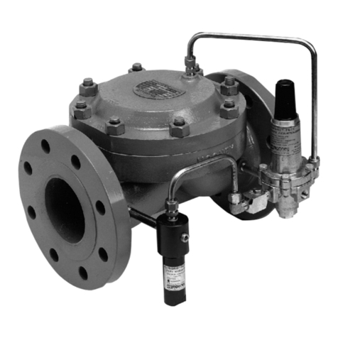
GE Masoneilan 173 Series User manual

GE Oil & Gas
Masoneilan*
173 Series
Self Operating Pressure Regulators
Instruction Manual
GE Data Classification : Public

ii | GE Oil & Gas
© 2016 General Electric Company. All rights reserved.
THESE INSTRUCTIONS PROVIDE THE CUSTOMER/OPERATOR WITH IMPORTANT PROJECT-SPECIFIC
REFERENCE INFORMATION IN ADDITION TO THE CUSTOMER/OPERATOR’S NORMAL OPERATION
AND MAINTENANCE PROCEDURES. SINCE OPERATION AND MAINTENANCE PHILOSOPHIES VARY,
GE (GENERAL ELECTRIC COMPANY AND ITS SUBSIDIARIES AND AFFILIATES) DOES NOT ATTEMPT
TO DICTATE SPECIFIC PROCEDURES, BUT TO PROVIDE BASIC LIMITATIONS AND REQUIREMENTS
CREATED BY THE TYPE OF EQUIPMENT PROVIDED.
THESE INSTRUCTIONS ASSUME THAT OPERATORS ALREADY HAVE A GENERAL UNDERSTANDING
OF THE REQUIREMENTS FOR SAFE OPERATION OF MECHANICAL AND ELECTRICAL EQUIPMENT
IN POTENTIALLY HAZARDOUS ENVIRONMENTS. THEREFORE, THESE INSTRUCTIONS SHOULD
BE INTERPRETED AND APPLIED IN CONJUNCTION WITH THE SAFETY RULES AND REGULATIONS
APPLICABLE AT THE SITE AND THE PARTICULAR REQUIREMENTS FOR OPERATION OF OTHER
EQUIPMENT AT THE SITE.
THESE INSTRUCTIONS DO NOT PURPORT TO COVER ALL DETAILS OR VARIATIONS IN EQUIPMENT
NOR TO PROVIDE FOR EVERY POSSIBLE CONTINGENCY TO BE MET IN CONNECTION WITH
INSTALLATION, OPERATION OR MAINTENANCE. SHOULD FURTHER INFORMATION BE DESIRED
OR SHOULD PARTICULAR PROBLEMS ARISE WHICH ARE NOT COVERED SUFFICIENTLY FOR THE
CUSTOMER/OPERATOR’S PURPOSES THE MATTER SHOULD BE REFERRED TO GE.
THE RIGHTS, OBLIGATIONS AND LIABILITIES OF GE AND THE CUSTOMER/OPERATOR ARE STRICTLY
LIMITED TO THOSE EXPRESSLY PROVIDED IN THE CONTRACT RELATING TO THE SUPPLY OF THE
EQUIPMENT. NO ADDITIONAL REPRESENTATIONS OR WARRANTIES BY GE REGARDING THE
EQUIPMENT OR ITS USE ARE GIVEN OR IMPLIED BY THE ISSUE OF THESE INSTRUCTIONS.
THESE INSTRUCTIONS ARE FURNISHED TO THE CUSTOMER/OPERATOR SOLELY TO ASSIST IN THE
INSTALLATION, TESTING, OPERATION, AND/OR MAINTENANCE OF THE EQUIPMENT DESCRIBED.
THIS DOCUMENT SHALL NOT BE REPRODUCED IN WHOLE OR IN PART WITHOUT THE WRITTEN
APPROVAL OF GE.

Masoneilan 173 Series Pressure Regulator Instruction Manual | iii
© 2016 General Electric Company. All rights reserved.
Table of Contents
Safety Information......................................................................................................................................................................1
About this Manual.......................................................................................................................................................................1
Warranty ......................................................................................................................................................................................... 1
1. General Information ............................................................................................................................... 2
2. Transport, Storage and Handling ........................................................................................................ 2
3. Installation and Assembly Instructions 173 Series Pressure Regulator
3.1 Cross-Section Drawing............................................................................................................................................... 3
3.2 Installation........................................................................................................................................................................ 4
3.3 Start-Up and Calibration............................................................................................................................................4
3.4 Maintenance ...................................................................................................................................................................5
4. Installation and Assembly Instructions – 173-50 Differential Pressure Regulator
4.1 Cross-Section Drawing – 173-50 Single Diaphragm....................................................................................6
4.2 Cross-Section Drawing – 173-50 Double Diaphragm ................................................................................. 7
4.3 Installation........................................................................................................................................................................ 8
4.4 Start-Up and Calibration............................................................................................................................................8
4.5 Maintenance ..................................................................................................................................................................8

Masoneilan 173 Series Pressure Regulator Instruction Manual | 1
© 2016 General Electric Company. All rights reserved.
Safety Information
Important - Please Read Before Installation
GE’sMasoneilan173SeriesPressureRegulator instructionscontain
DANGER, WARNING, and CAUTION labels, where necessary, to
alert you to safety related or other important information. Read
the instructions carefully before installing and maintaining your
control valve. DANGER and WARNING hazards are related to
personal injury. CAUTION hazards involve equipment or property
damage. Operation of damaged equipment can, under certain
operational conditions, result in degraded process system
performance that can lead to injury or death. Total compliance
with all DANGER, WARNING, and CAUTION notices is required
for safe operation.
This is the safety alert symbol. It alerts you to potential
personal injury hazards. Obey all safety messages that
follow this symbol to avoid possible injury or death.
Indicates a potentially hazardous situation which, if not avoided,
could result in death or serious injury.
Indicates a potentially hazardous situation which, if not avoided,
could result in serious injury.
Indicates a potentially hazardous situation which, if not avoided,
could result in minor or moderate injury.
When used without the safety alert symbol indicates a
potentially hazardous situation which, if not avoided, could
result in property damage.
Note: Indicates important facts and conditions.
About this Manual
• The information in this manual is subject to change without
prior notice.
• The information contained in this manual, in whole or part,
shall not be transcribed or copied without GE’s written
permission.
• Please report any errors or questions about the information in
this manual to your local supplier.
• These instructions are written specifically for the 173 Series back
pressure regulators, and do not apply to other regulators
outside of this product line.
Warranty
Items sold by General Electric are warranted to be free from
defects in materials and workmanship for a period of one
year from the date of shipment provided said items are used
according to GE recommended usages. GE reserves the right
to discontinue manufacture of any product or change product
materials, design or specifications without notice.
This instruction manual applies to the Masoneilan 173 Series
back
pressure regulators.
Note:
• The regulator MUST BE installed, put into
service and maintained by qualified and
competent professionals who have undergone
suitable training.
• Under certain operating conditions, the use of damaged
equipment could cause a degradation of the performance
of the system which may lead to personal injury or death.
• Changes to specifications, structure, and components used
may not lead to the revision of this manual unless such
changes affect the function and performance of the product.
• All surrounding pipe lines must be thoroughly flushed to
ensure all entrained debris has been removed from the
system.

2 | GE Oil & Gas
© 2016 General Electric Company. All rights reserved.
1. General Information
The following instructions are designed to assist maintenance
personnel in performing most of the maintenance required on
the 173 Series regulators, and if followed carefully, will reduce
maintenance time.
GE has highly skilled Service Engineers available for start-up,
maintenance and repair of our regulators and component
parts. In addition, regularly scheduled training programs are
conducted to train customer service and instrumentation
personnel in the operation, maintenance and application
of our control valves, regulators and instrumentation.
Arrangements for these services can be made through your GE
Representative or District Office. When performing maintenance
,use only genuine GE replacement parts. Parts are obtainable
through your local GE Representative or District Office. When
ordering parts always include the MODEL and SERIAL NUMBER of
the unit being repaired.
2. Transport, Storage and Handling
Transport
Depending on their size, regulators can be transported loose or
packed, in cardboard boxes or in wooden crates.
All the regulator ends are fitted with covers to prevent dirt from
entering. Units can be placed on pallets if required. Follow all
instructions noted on the packaging.
Operators moving loads must take all necessary precautions to
prevent accidents.
Storage
Regulators must be kept in a dry place to protect them from
atmospheric conditions. They may only be removed from their
crates or packing immediately prior to installation.
The end protections and covers must be kept on until installation.
Regulators, whether packed or not, must not be subject to impact.
Regulators, whether packed or not, must always be kept
upright, that is, never lying on one side, in order to prevent
distortion and damage to internal parts.
Handling
When unpacking the regulators and removing the end protectors
immediately prior to installation, take great care to make sure
that foreign material does not enter the regulator inlet and outlet
ports while it is being connected.
When handling the regulator, make sure the work area is
kept clear in order to prevent injury to people and damage to
property.
1st
1
2nd
7
3rd
3
1st
X
2nd
X
3rd
X
4th
X
Option
X
Regulator Series Action
1 Relieving
Metal Seat
2 Relieving
Soft Seat
Action
50 Differential
Pressure
Diaphragm
1 Metal
Diaphragm
2 Elastomeric
Diaphragm
Trim Size
01
05
08
10
12
16
20
35
45

Masoneilan 173 Series Pressure Regulator Instruction Manual | 3
© 2016 General Electric Company. All rights reserved.
3. Installation and Assembly Instructions - 173 Series Pressure Regulator
3.1 Cross-section Drawing
Figures 1 through 5 below show the cross-sectional view of the
173 Series regulators along with part names and versions.
ATEX Construction Gr. II Cat. 2
Ref. Part Name
1 Blindhead
*2 Gasket Set
3 Body
4 Guide
5 Diaphragm Case
6 Ball
7 Diaphragm Plate (Upper)
*8 Diaphragm
*9 Protector - optional
*10 O-Ring
11 Spring Case
12 Spring
13 Adjusting Screw
14 Lock Nut
15 Spring Button
16 Nut
17 Spring Guide
18 Screw
19 Nut
20 Diaphragm Plate - Lower
21 Screw
*22 Plug
*23 Ring
*24 Disc
*25 Seat
*26 Screw
*27 Gasket Plate
28 Cap
*Recommended spare parts.
Figure 1
Figure 5
Figure 3 Figure 4
*9 - (only on request)
Figure 2

4 | GE Oil & Gas
© 2016 General Electric Company. All rights reserved.
made from carbon and stainless steel (as shown in Fig-
ure 4), the hole (5) (as shown in Figures 6 and 7) is al-
ways threaded ¼"NPT and must be connected to the pipe
conveying the discharge to a suitable place (safely and
constantly at atmospheric pressure).
3.2.4 Bear in mind that the regulated pressure sensing port is
located inside the regulator, therefore the pressure drops in the
inter-connecting piping between the regulator and the point of
use will affect the accuracy of the maintained set pressure. This
pressure drop must be considered when calculating the size of
the connection piping.
3.2.5 When it is essential to avoid pressure variations at the point
of use, the regulators are fitted with an external sensing line con-
nection, as shown in Fig 8. The 1/8" female threaded port must
be connected to a nipple as near as possible to the point of use.
Figure 8
External sensing line (only on request)
3.3 Start-Up and Calibration
3.3.1 The 173 Series pressure regulators are shipped with a
pressure setting at the low end of the adjustable range un-
less otherwise specified by the customer. The pressure setting
can be changed to any value within the adjustable range by
loosening the adjusting screw locknut (14) and turning the
adjusting screw (13) clockwise to increase the pressure setting or
counterclockwise to decrease the pressure setting.
During regulator start-up or operation, do not touch any part of
the regulator as this can conduct heat if the fluid used is at a high
temperature.
3.2 Installation
3.2.1 173 Series regulators must be installed with the actuator
(2) facing upwards and the diaphragm perfectly horizontal, as
shown in Fig.6.
In pressure reducing applications regulating very low down-
stream pressures (normally lower than 100 mm water column),
the regulator must be installed with the actuator facing down-
wards and perfectly horizontal (below pipeline) as indicated by
the nameplate orientation as shown in Fig. 7.
3.2.2 Before installation, ensure that the piping is clean and free
of any debris (machining chips, weld slag, etc). Contaminants
remaining in the piping system can damage internal compo-
nents of the regulator.
When welding piping, do not attach the earth connector to the
regulator as this may damage important sliding parts.
Figure 6
1) Adjustment screw (spring holder)
2) Actuator
3) Pressure gauge
4) Regulator body
5) Drain hole
Figure 7
3.2.3 WARNING/CAUTION ON ATEX USAGE: When handling or
working with harmless fluids (for instance, inert gases, like nitrogen,
carbon dioxide and noble gases) the spring cover is not normally
airtight (ATEX construction, Group II- Cat.2), and has a hole (5) (as
shown in Figure 6) that prevents it from pressurizing if the
diaphragm breaks. If the spring cover is airtight, and
This pipe shall be linked in
case of ATEX construction
Gr. II Cat.2 for flammable
fluids, and must convey to a
suitable place.
Diameter 1/8”
screwed BSP
Pressure
sensing

Masoneilan 173 Series Pressure Regulator Instruction Manual | 5
© 2016 General Electric Company. All rights reserved.
3.4.2.4 Reassembly
Carry out the disassembly operations in reverse order.
Push the stem of the plug into body and push it into its guide.
Tighten the seat (25), making sure the washer is new and cor-
rectly positioned. Replace the small retention ring (10) after thor-
oughly cleaning its seat.
Install the diaphragm, taking care to install the protector (9), if
applicable, underneath, towards the regulator body on top of the
lower diaphragm plate (20). Install the upper diaphragm plate (7)
and the spring guide (17) and fully tighten the nut (16).
Align the holes of the diaphragm with those in the actuator
flange and install the spring, spring holder and spring case.
Install the blindhead (1). Return the adjusting screw (13) to the
position marked by the nut (14) or the position noted (see 3.4.2.1).
Exact adjustment must be checked when the regulator is returned
to service.
3.4.2.5 Diaphragm Replacement
The diaphragm may require replacement without having
to make other repairs. If the regulator is easy to access and
isolate, it can be replaced while leaving the regulator installed in
the piping. In this case, isolate the regulator and vent all pressure.
To prevent accidental pressurization while working on the regu-
lator, make sure that the isolation valves are locked. Remove the
actuator following the instructions in section 3.4.1.2.
Replace and install the diaphragm and reassemble the actuator
as shown in section 3.4.2.4. Check calibration once more when
the regulator is returned to service.
When welding piping, do not attach the earth connector to the
regulator as this may damage important sliding parts.
3.4 Maintenance
3.4.1 The required maintenance interval varies depending on
application. The user must establish a suitable interval based on
the operating conditions. Prior to disassembly, remove all system
pressure from the regulator.
Before starting the above operation, make sure the recommend-
ed spare parts are available (refer to the parts list indicated in
Figures 1 through 5).
3.4.2 Disassembly
Refer to Figures 1 through 5 while completing the following dis-
assembly procedures.
3.4.2.1 Actuator Disassembly
Remove spring compression by turning the adjustment screw
(13) counterclockwise after loosening the locknut (14). The posi-
tion of the locknut should be noted to allow closer preliminary
adjustment when reassembling. If the regulator is equipped with
a sealed cap (as shown in Figure 4), first remove the cap (28) and
gasket.
Remove the spring case (11) by loosening the nuts (19).
Note: It is not necessary to remove the housings on actuator siz-
es 220 and 360.
Remove the spring. Unscrew the nut (16).
Remove the diaphragm and washers.
3.4.2.2 Body Disassembly
Unscrew and remove the blindhead (1) with gasket. Unscrew the
seat (25) with a screwdriver (refer to Figures 1, 2, and 5).
Pull the plug off its guide and remove it from the body.
3.4.2.3 Parts Inspection
All the components are now ready to be inspected. Replace any
worn items. Clean all parts.
Pay particular attention to the condition of the disk and plug,
both elastomeric and metal, and the seat.
If the seat is worn, it may be able to be restored by lapping
using a metal disk and abrasive paste.
The diaphragm should be replaced if it shows any damage. The
same applies to the Teflon diaphragm protector (if included).
Gaskets should not be reused.
If preferred, the regulator may be returned to one of GE’s autho-
rized Masoneilan repair centers (MARC) repair center to be recon-
ditioned.

6 | GE Oil & Gas
© 2016 General Electric Company. All rights reserved.
Figure 9
4. Installation and Assembly Instructions - 173-50 Differential Pressure Regulator
There are two distinct types of 173-50 Series differential pressure regulators – those with a single diaphragm and those with a
double diaphragm.
4.1 Cross-Section Drawing 173-50 Single Diaphragm
In regulators with a single diaphragm (as shown in Figure 9), one of the controlled pressures acts under the diaphragm
through an internal sensing line connection on the spring housing. The plug is kept closed by the spring.
Ref. Part Name
1 Blindhead
*2 Gasket Set
3 Body
4 Guide
5 Diaphragm Case
6 Diaphragm Plate (Upper)
*7 Diaphragm
*8 O-Ring
9 Spring Case
10 Spring
11 Nut
12 Screw
*13 Gasket
14 Lock Nut
15 Packing Gland
*16 Bearing
17 Spring Button
18 Adjusting Screw
19 Spring Guide
20 Screw
21 Nut
22 Screw
*23 Plug
*24 Ring
*25 Disc
*26 Seat
*27 Screw
28 Gasket Plate
*Recommended spare parts.

Masoneilan 173 Series Pressure Regulator Instruction Manual | 7
© 2016 General Electric Company. All rights reserved.
4.2 Cross-Section Drawing 173-50 Double Diaphragm
These regulators shown in Figure 10 have two diaphragms separated by a chamber that communicates with the outside.
The controlled pressures act under the lower diaphragm (through an internal sensing line connection) and over the upper
diaphragm (through a sensing line nipple on the spring housing). The plug is kept closed by the spring.
Figure 10
Ref. Part Name
1 Blindhead
*2 Gasket Set
3 Body
4 Guide
5 Diaphragm Case
6 Diaphragm Plate (Upper)
*7 Diaphragm
*8 O-Ring
9 Spring Case
10 Spring
11 Nut
12 Screw
*13 Gasket
14 Packing Gland
15 Lock Nut
*16 Bearing
17 Spring Button
18 Adjusting Screw
19 Spring Guide
20 Screw
21 Nut
22 Screw
*23 Plug
*24 Ring
*25 Disc
*26 Seat
*27 Screw
28 Gasket Plate
29 Nute
30 Actuator Ring
31 Intermediate
*Recommended spare parts.

8 | GE Oil & Gas
© 2016 General Electric Company. All rights reserved.
4.3 Installation
4.3.1 Positioning
All 173-50 regulators must be installed with the actuator facing
upwards and the diaphragm horizontal.
4.3.2 Installation Diagrams
In most cases the flow crosses the regulator as shown by the
arrow in Figures 9 and 10.
The installation diagrams are therefore as follows:
Figure 11
Example of installation layout for 173-50 single diaphragm
regulators
Figure 12
Example of installation layout for 173-50 double diaphragm
regulators
4.3.3 Isolation Valves and Filter/Pressure Gauges
Install an isolation valve upstream, downstream and on the
sensing and discharge line connection piping, in order to service
the regulator (if necessary) while the plant is pressurized.
Install one filter or pressure gauge upstream from the regulator
and another one on the sensing line connection (as shown in
Figures 11 and 12) in order to calibrate the differential pressure
and keep it constantly under control.
4.3.4 Contamination
Prior to installing the regulator in the piping, make sure the inside
of the pipes are clean and free of any debris (machining cuttings,
weld slag, etc.), especially the upstream section; blow down the
piping if possible to eliminate any remaining dirt: small drops of
weld slag may seriously damage the regulator.
4.3.5 Double Diaphragm Discharge Venting
In double diaphragm regulators, the chamber between the two
diaphragms must be connected to piping to vent the discharge
to a suitable place, safely and constantly at atmospheric
pressure. This hole can be closed with a plug or pressure gauge
with an electrical contact for the remote signaling that the
diaphragm has broken, as long as the downstream plant is
protected (as shown in Figure 12).
4.3.6 Safety Relief
If there is any chance that an overflow regulator failure could
cause the pressure upstream from the reduction regulator to
exceed the maximum admissible pressure for the installation,
a safety relief valve must be installed upstream – without an
isolation valve in between – in order to discharge the entire flow
crossing the differential pressure regulator.
4.3.7 Pressure Drops
Because the regulated pressure sensing port is located inside
the regulator, the pressure drops in the inter-connecting piping
between the regulator and the point of use will affect the
accuracy of the maintained set pressure. This pressure drop
must be considered when calculating the size of the connection.
4.3.8 Pressure Variation
When it is essential to avoid pressure variations at the point
of use, the regulators are fitted with an external sensing line
connection that replaces the internal connection and is fitted
to the lower flange of the actuator. This connection must be
connected as near as possible to the point of use where the
installation of a pressure gauge is also recommended.
4.4 Startup and Calibration
(Refer to Figures 9 and 10)
4.4.1 Pressure Difference
This operation is similar for both single diaphragm and double
diaphragm regulators. The sensing line connection regulator and
the upstream and downstream isolation valves must be closed.
Slightly open the downstream valve and then the upstream
valve together with the sensing line connection, making sure
that the pressure difference read on the pressure gauges is
correct. If necessary, to reduce the pressure difference, turn the
adjustment screw (18) clockwise to increase differential pressure
and counterclockwise to decrease.
4.1.2 Calibration
When the required value is reached, fully open all the valves.
When the downstream system is working at full power, calibrate
by adjusting the screw (18).
4.5 Maintenance
(Refer to Figures 9 and 10)
4.5.1 Maintenance Interval
The required maintenance interval will vary depending on
application. The user must establish a suitable maintenance
schedule depending on the operating conditions. Prior to
disassembly, remove all system pressure from the regulator.
Before starting the above operation, make sure the recommended
spare parts are available (See the parts listed in Figures 9 and 10).

Masoneilan 173 Series Pressure Regulator Instruction Manual | 9
© 2016 General Electric Company. All rights reserved.
4.5.2 Disassembly
Disassembling and reassembling operations for all types of
173-50 regulators as long as the diaphragms are considered.
These are:
- 1 single elastomeric diaphragm for 173-50 single diaphragm
regulators;
- 2 elastomeric diaphragms (one per side) for 173-50 double
diaphragm regulators.
Make sure the spares match the above and take great care
when mounting the diaphragm assembly.
4.5.2.1 Actuator Disassembly
Release the spring compression by turning the adjustment
screw counterclockwise, counting and noting the number of
turns in order to restore calibration after reassembly. Remove
the spring housing (9) by loosening the nuts (21). It is not
necessary to remove the housings of the 220 and 360 actuators.
Remove the spring.
- For single diaphragm regulators: unscrew the nut (11) and
remove the diaphragm with the diaphragm plate (6) and
spring guide (19). (See Figure 9)
- For double diaphragm regulators: unscrew the lock nut (11)
and nut (29) and remove the double diaphragm assembly
with ring (30), intermediate plate (31), diaphragm plate (6) and
spring guide (19). (See Figure 10)
4.5.2.2 Body Disassembly
Unscrew and remove the cover with relevant gasket. Unscrew
the seat with a screwdriver. (See Figures 9 and 10)
Pull the plug off its guide and remove it from the body.
4.5.3 Parts Inspection
(Refer to Figures 9 and 10)
All of the components are now ready to be inspected. Replace
any worn items. Clean all parts.
Pay particular attention to the condition of the disc of the plug
(24), both elastomeric and metal, and the seat.
If the seat is worn, it may be able to be restored by lapping using
a metal disc and abrasive paste.
The diaphragm should be replaced if it shows any damage. The
same applies to the Teflon diaphragm protector (if included).
Gaskets should not be reused.
If preferred, the regulator may be returned to an authorized GE
repair center to be reconditioned.
4.5.4 Reassembly
Carry out the disassembly operations in reverse order. Push the
stem of the plug into its guide and tighten the seat (26). Screw
the cover (1) back on. Install the diaphragm/s (see section 4.5)
taking care to properly arrange the Teflon protectors. Make sure
the seats of the O-rings are perfectly clean before mounting
them. Assemble:
- For single diaphragm regulators: plug assembly, diaphragm
plate, diaphragm and spring guide (with gaskets), and nut.
- For double diaphragm regulators: plug assembly, diaphragm
plate, lower diaphragm, intermediate plate and actuator ring,
upper diaphragm, spring guide (with gaskets), nut and lock nut.
Match the holes of the diaphragm/s with the holes in the
actuator flange and install the spring, spring holder and housing.
Turn the adjustment screw the number of turns noted during
dismounting. Exact calibration must then be checked when the
regulator is placed back into service.
4.5.5 Replacing the Diaphragm
The diaphragm may require replacement without having to
make other repairs. If the regulator is easy to access and
isolate, it can be replaced while leaving the regulator installed
in the piping. In this case, isolate the regulator and vent all
pressure. To prevent accidental pressurization while working
on the regulator, make sure that the isolation valves are locked.
Remove the actuator following the instructions in section 4.5.2.
Replace and install the diaphragm and reassemble
the actuator as shown in section 4.5, 4.5.3 and 4.5.6. Check
calibration once more when the regulator is returned
to service.

10 | GE Oil & Gas
© 2016 General Electric Company. All rights reserved.

Masoneilan 173 Series Pressure Regulator Instruction Manual | 11
© 2016 General Electric Company. All rights reserved.

12 | GE Oil & Gas
© 2016 General Electric Company. All rights reserved.

DISTRIBUTOR
* Trademark of the General Electric Company.
Other company names and product names used in this document are
the registered trademarks or trademarks of their respective owners.
© 2014 General Electric Company. All rights reserved.
Visit our web-site:
www.fr-eps.com
E.P. & S. - FRANCE
24 bis rue de Picpus
75012 PARIS
Tel: +33 (0) 762 682 291
Tel: +33 (0) 650 590 965
ventes@fr-eps.com
E.P. & S. - CAMEROON
Immeuble Carré d’Or
Rue Soppo Priso Côté Chococho, Bonapriso
DOUALA
Tel: +237 6 52 12 70 95
Tel: +33 (0) 782 006 276
ventes@fr-eps.com
Table of contents
Other GE Controllers manuals
Popular Controllers manuals by other brands

GREISINGER
GREISINGER gir 2000Pt Mounting and operating manual

Mitsubishi Electric
Mitsubishi Electric MELSEC iQ-R Series user manual

Eaton
Eaton EDS Series Installation & maintenance information

Emerson
Emerson Dixell XR44CH Installing and operating instructions

TECshow
TECshow NAVIGATOR 24 MKII user manual

Bartec
Bartec MAK 3003 manual