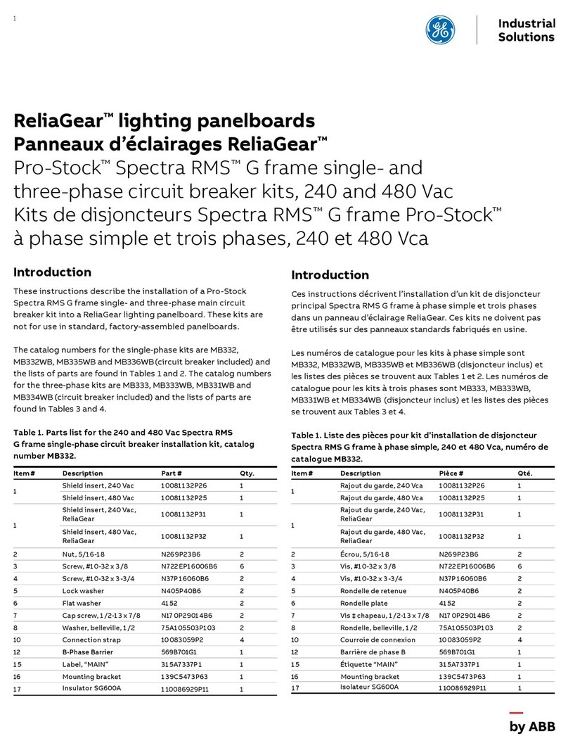
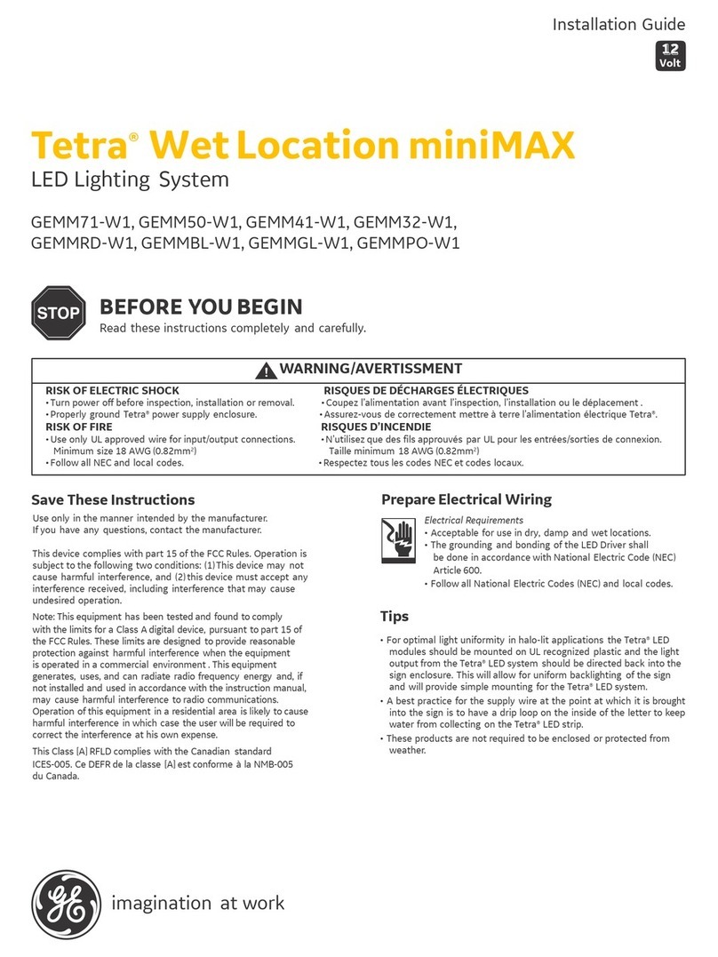
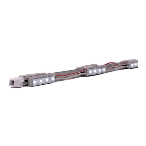
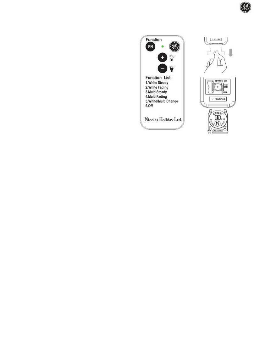
GE Tetra miniMAX User manual

GE
Lumination
Installation Guide Installation Guide
12
Volt
1
23
45
1
2
3
4
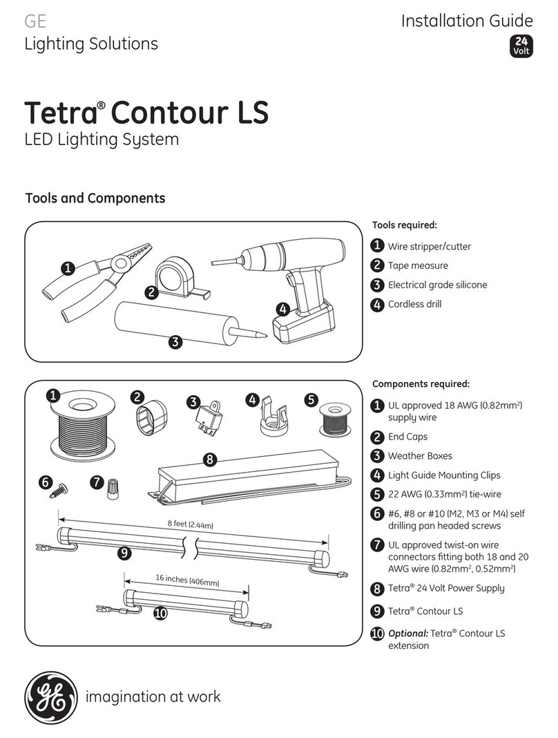
Components:
5
UL approved 18 AWG (0.82 mm2)
supply wire
UL approved 22-14 AWG
(0.33-2.08 mm2) wire connectors
or 22-18 AWG (0.33-0.82 mm2)
in-line/IDC connectors
#6 or #8 (M3 or M4) screws or
1/8 inch (3.2 mm) rivets
Power Supply (GEPS12-20,
GEPS12-60 or GEPS12-60U)
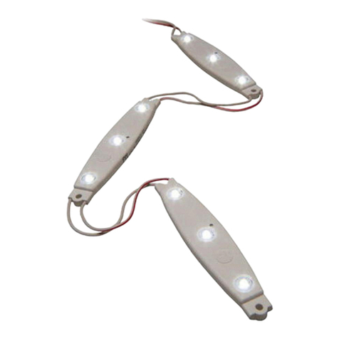
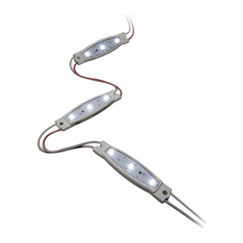
Tetra® miniMAX LED modules
Components
imagination at work
Tetra® miniMAX
LED Lighting System
Symptom Solution
All letters are OFF • Check AC input connetion and/or check circuit breaker.
• Check wire connection(s) at the Tetra® LED System and power supply for improper
termination(s) or short circuits. Properly terminate or replace the wire connection(s).
• Check that connections are the red striped wire (+) of the LED strip to the red wire (+) of the
power supply and the white wire (-) of the LED strip to the black wire (-) of the power supply.
Some LEDs appear dim • Ensure the overall length of the Tetra® LED System does not exceed the maximum load.
• Ensure the length of supply wire is equal to or below the recommended remote mounting
distance.
Some of the letters are
not illuminated
• Check wire connection(s) at the Tetra® LED System and power supply for improper
termination(s) or short circuits. Properly terminate or replace the wire connection(s).
• Check that connections are the red striped wire (+) of the LED strip to the red wire (+) of the
power supply and the white wire (-) of the LED strip to the black wire (-) of the power supply.
Shadows • Re-route supply wire and secure to the back of the can with silicone. Adjust wire
connector orientation so that it does not cover any LEDs.
• Adjust LED layout to ensure uniformity of illumination on the face of the letter.
Troubleshooting
SIGN055-R082409
(GEWHMMS5, GEWWMMS5, GERDMMS5, GEGLMMS5, GEBLMMS5)
RISK OF ELECTRIC SHOCK:
• Turn power OFF before inspection, installation
or removal.
• Properly ground Tetra Power Supply enclosure.
RISK OF FIRE:
• Follow all NEC and local codes.
• Use only UL approved wire for input/output
connections. Minimum size 18 AWG (0.82 mm2)
WARNING!
BEFORE YOU BEGIN
Read these instructions completely and carefully.
Prepare Electrical Wiring
Electrical Requirements
• Do not use in wet locations.
• The grounding and bonding of the LED Driver
shall be
done in accordance with National Electric
Code (NEC)
Article 600.
• Follow all National Electric Codes (NEC) and local codes.
Risk of electrical shock. Disconnect power before servicing or
installing product.
Risque de choc électrique. Couper l’alimentation avant
le dépannage ou avant l’installation du produit.
WARNING / AVERTISSMENT
6180 Halle Drive • Valley View, Ohio 44125-4635 • USA
P: 216.606.6555 • F: 216.606.6599 • www.lumination.com • info@lumination.com
Lumination, LLC is a subsidiary of the General Electric Company. Tetra is a trademark of Lumination, LLC. The GE brand, logo, and ecomagination are trademarks of the General Electric Company.
© 2009 Lumination, LLC. Information provided is subject to change without notice. All values are design or typical values when measured under laboratory conditions.
For customer service & technical support, contact:
1-888-MY-GE-LED (1.888.694.3533)
Tips
• Tetra LED systems are rated for damp location use by UL, and should be protected from direct exposure to moisture
(i.e., rain & snow).
• For optimal light uniformity in halo-lit applications the Tetra LED modules should be mounted on UL recognized plastic
and the light output from the Tetra LED system should be directed back into the sign enclosure. This will allow for
uniform backlighting of the sign and will provide simple mounting for the Tetra LED system.
• When mounting LED modules for halo-lit applications the clear acrylic should be recessed into the body of the sign or
a bead of silicone should be applied to provide a barrier against the elements.
• A best practice for the supply wire at the point at which it is brought into the sign is to have a drip loop on the inside of
the letter to keep water from collecting on the Tetra LED strip.
IP66 rated: separate enclosure required for outdoor use, UL damp location rated
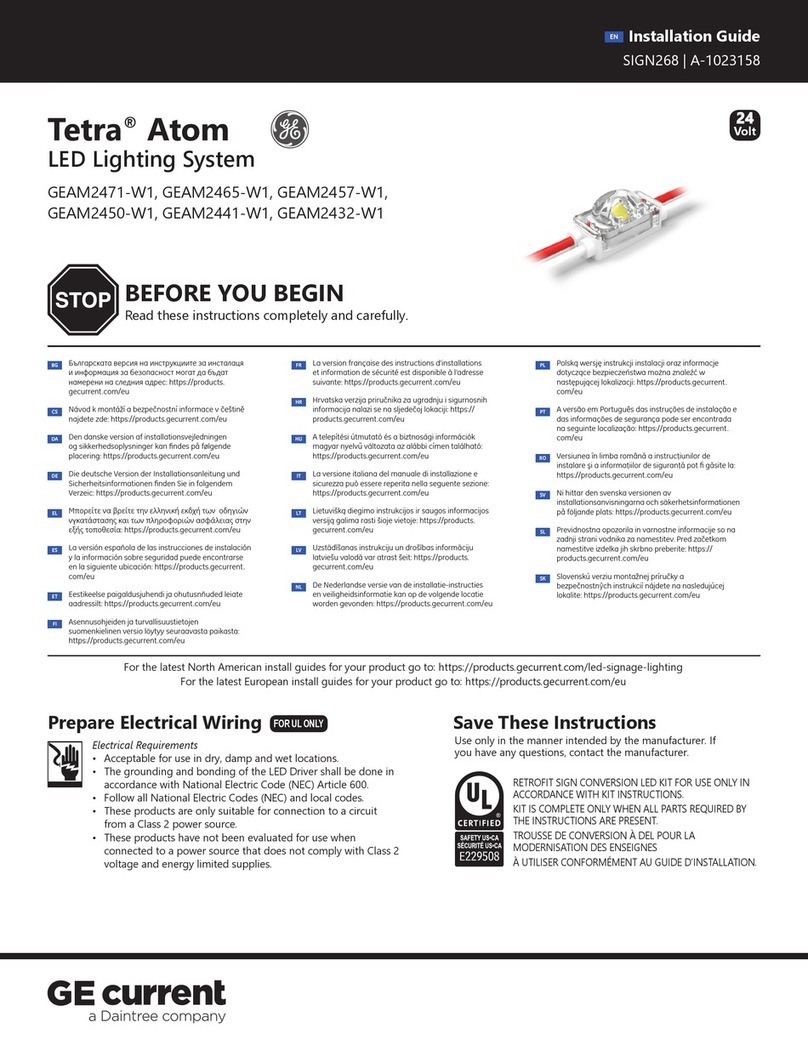
Conforms to the following standards:
Installation GuideInstallation Guide
Connect LED strips using in-line (IDC) connectors
or twist-on wire connectors.
Must cap all exposed wires with appropriate wire
connectors.
Run a wire from the Power Supply to each
channel letter and connect to the first LED
module on the strip.
Must be used with the GEPS12-20, GEPS12-60 or
GEPS12-60U Power Supplies (12-Volt).
NOTE: Refer to the Power Supply Installation
Instructions for loading and remote mounting
information.
1 2
3
Measure and cut Tetra LED strip to the appropriate
length for each letter.
Cuts can be made between any of the modules.
Remove tape backing and stick LED modules
into place.
Continue until you have reached the end of the
strip.
2
3
Clean & remove all debris from the inside of the
channel letter. Replace sign face.
NOTE: For halo-lit applications LED modules should
be mounted on UL recognized clear acrylic or
polycarbonate. The light output from the LED system
should be directed back into the sign enclosure. This will
allow for uniform backlighting of the sign and will provide
simple mounting and protection against moisture.
Drill a 1/4-inch (6.4 mm) hole near the LED strip
and grommet the hole for supply wire access.
Use rivets or screws to secure the LED strip within
the channel letter.
Use #6 (M3) or #8 (M4) pan headed metal screws
or 1/8-inch (3.2 mm) rivets.
4
5 6
Clean & remove all debris from the inside of the
channel letter before you begin.
1
To power supply
Red (+)
Red stripe (+)
White (-)
Black (-)
Connect the red stripe wire (+) of the LED strip to
the red wire (+) of the power supply. Connect the
white wire (-) of the LED strip to the black wire (-) of
the power supply.
NOTE: All electrical connections should be made
within the letter.
4
Power
Supply
To Tetra LED System
Red (+)
Black (-)
Red stripe (+)
White (-)
Step 1: Layout Modules Step 2: Electrical Connections

GE
Lumination
Installation Guide Installation Guide
12
Volt
1
23
45
1
2
3
4
Components:
5
UL approved 18 AWG (0.82 mm2)
supply wire
UL approved 22-14 AWG
(0.33-2.08 mm2) wire connectors
or 22-18 AWG (0.33-0.82 mm2)
in-line/IDC connectors
#6 or #8 (M3 or M4) screws or
1/8 inch (3.2 mm) rivets
Power Supply (GEPS12-20,
GEPS12-60 or GEPS12-60U)
Tetra® miniMAX LED modules
Components
imagination at work
Tetra® miniMAX
LED Lighting System
Symptom Solution
All letters are OFF • Check AC input connetion and/or check circuit breaker.
• Check wire connection(s) at the Tetra® LED System and power supply for improper
termination(s) or short circuits. Properly terminate or replace the wire connection(s).
• Check that connections are the red striped wire (+) of the LED strip to the red wire (+) of the
power supply and the white wire (-) of the LED strip to the black wire (-) of the power supply.
Some LEDs appear dim • Ensure the overall length of the Tetra® LED System does not exceed the maximum load.
• Ensure the length of supply wire is equal to or below the recommended remote mounting
distance.
Some of the letters are
not illuminated
• Check wire connection(s) at the Tetra® LED System and power supply for improper
termination(s) or short circuits. Properly terminate or replace the wire connection(s).
• Check that connections are the red striped wire (+) of the LED strip to the red wire (+) of the
power supply and the white wire (-) of the LED strip to the black wire (-) of the power supply.
Shadows • Re-route supply wire and secure to the back of the can with silicone. Adjust wire
connector orientation so that it does not cover any LEDs.
• Adjust LED layout to ensure uniformity of illumination on the face of the letter.
Troubleshooting
SIGN055-R082409
(GEWHMMS5, GEWWMMS5, GERDMMS5, GEGLMMS5, GEBLMMS5)
RISK OF ELECTRIC SHOCK:
• Turn power OFF before inspection, installation
or removal.
• Properly ground Tetra Power Supply enclosure.
RISK OF FIRE:
• Follow all NEC and local codes.
• Use only UL approved wire for input/output
connections. Minimum size 18 AWG (0.82 mm2)
WARNING!
BEFORE YOU BEGIN
Read these instructions completely and carefully.
Prepare Electrical Wiring
Electrical Requirements
• Do not use in wet locations.
• The grounding and bonding of the LED Driver
shall be
done in accordance with National Electric
Code (NEC)
Article 600.
• Follow all National Electric Codes (NEC) and local codes.
Risk of electrical shock. Disconnect power before servicing or
installing product.
Risque de choc électrique. Couper l’alimentation avant
le dépannage ou avant l’installation du produit.
WARNING / AVERTISSMENT
6180 Halle Drive • Valley View, Ohio 44125-4635 • USA
P: 216.606.6555 • F: 216.606.6599 • www.lumination.com • inf[email protected]
Lumination, LLC is a subsidiary of the General Electric Company. Tetra is a trademark of Lumination, LLC. The GE brand, logo, and ecomagination are trademarks of the General Electric Company.
© 2009 Lumination, LLC. Information provided is subject to change without notice. All values are design or typical values when measured under laboratory conditions.
For customer service & technical support, contact:
1-888-MY-GE-LED (1.888.694.3533)
Tips
• Tetra LED systems are rated for damp location use by UL, and should be protected from direct exposure to moisture
(i.e., rain & snow).
• For optimal light uniformity in halo-lit applications the Tetra LED modules should be mounted on UL recognized plastic
and the light output from the Tetra LED system should be directed back into the sign enclosure. This will allow for
uniform backlighting of the sign and will provide simple mounting for the Tetra LED system.
• When mounting LED modules for halo-lit applications the clear acrylic should be recessed into the body of the sign or
a bead of silicone should be applied to provide a barrier against the elements.
• A best practice for the supply wire at the point at which it is brought into the sign is to have a drip loop on the inside of
the letter to keep water from collecting on the Tetra LED strip.
IP66 rated: separate enclosure required for outdoor use, UL damp location rated
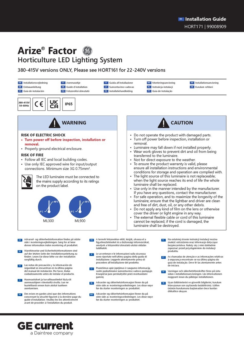
Conforms to the following standards:
Other GE Lighting Equipment manuals

GE
GE HO HO HO User manual

GE
GE Arize Element L1000 Gen2 User manual

GE
GE ReliaGear 400 A User manual

GE
GE Tetra EdgeStrip HO User manual

GE
GE LED 100 C5 LIGHTS User manual

GE
GE 19005LO User manual

GE
GE Albeo ABR2 User manual

GE
GE Tetra Contour LS User manual

GE
GE 79556 User manual

GE
GE 3LED-C5-50 User manual
Popular Lighting Equipment manuals by other brands

Light Emotion
Light Emotion LX90SPOT user manual

Rollei
Rollei Lumen Pro RGB 50 W / 100 W manual

MELINERA
MELINERA Z30893A Operation and safety notes

IMRELAX
IMRELAX IM-MH0610 user manual

GREENLED
GREENLED PHI ARROW 1245 Installation instruction

Mega LED Lighting
Mega LED Lighting LED COB PAR LIGHT-100 user manual