manuals.online logo
Brands
  1. Home
  2. •
  3. Brands
  4. •
  5. GE
  6. •
  7. Lighting Equipment
  8. •
  9. GE current Tetra miniMAX GEMM71-W1 User manual

GE current Tetra miniMAX GEMM71-W1 User manual

Installation Guide
12
Volt
Tetra® Wet Location miniMAX
LED Lighting System
GEMM71-W1, GEMM50-W1, GEMM41-W1, GEMM32-W1,
GEMMRD-W1, GEMMBL-W1, GEMMGL-W1, GEMMPO-W1
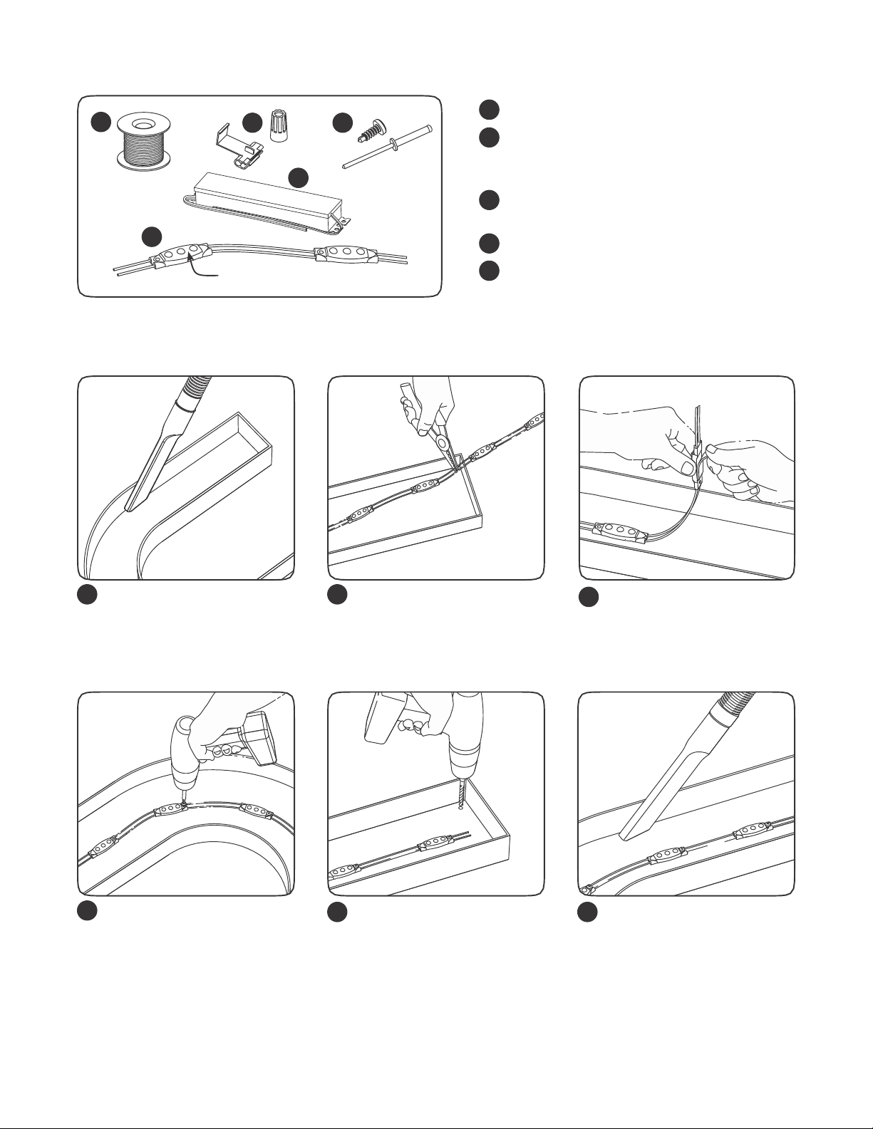
BEFORE YOU BEGIN
Read these instructions completely and carefully.
Save These Instructions
Use only in the manner intended by the manufacturer.
If you have any questions, contact the manufacturer.
Prepare Electrical Wiring
Electrical Requirements
•Acceptable for use in dry, damp and wet locations.
•The grounding and bonding of the LED Driver shall
be done in accordance with National Electric Code (NEC)
Article 600.
•Follow all National Electric Codes (NEC) and local codes.
This device complies with part 15 of the FCC Rules. Operation is
subject to the following two conditions: (1)This device may not
cause harmful interference, and (2)this device must accept any
interference received, including interference that may cause
undesired operation.
Note: This equipment has been tested and found to comply
with the limits for a Class A digital device, pursuant to part 15 of
the FCC Rules. These limits are designed to provide reasonable
protection against harmful interferencewhenthe equipment
is operated in a commercial environment . This equipment
generates, uses, andcan radiate radio frequency energy and, if
not installed and used in accordance with theinstruction manual,
may cause harmful interference to radio communications.
Operation of this equipment in a residential area is likely to cause
harmful interference in which case the user will be required to
correcttheinterference at his own expense.
This Class [A] RFLD complies with the Canadian standard
ICES-005. Ce DEFR de la classe [A]est conforme à la NMB-005
du Canada.
Tips
•For optimal light uniformity in halo-lit applications the Tetra® LED
modules should be mounted on UL recognized plastic and the light
output from the Tetra® LED system should be directed back into the
sign enclosure. This will allow for uniform backlighting of the sign
and will provide simple mounting for the Tetra® LED system.
•A best practice for the supply wire at the point at which it is brought
into the sign is to have a drip loop on the inside of the letter to keep
water from collecting on the Tetra®LED strip.
•These products are not required to be enclosed or protected from
weather.
imagination at work
WARNING/AVERTISSMENT
RISK OF ELECTRIC SHOCK RISQUES DE DÉCHARGES ÉLECTRIQUES
•Turn power off before inspection, installation or removal. •Coupez l’alimentation avant l’inspection, l’installation ou le déplacement .
•Properly ground Tetra® power supply enclosure. •Assurez-vous de correctement mettre à terre l’alimentation électrique Tetra®.
RISK OF FIRE RISQUES D’INCENDIE
•Use only UL approved wire for input/output connections. •N’utilisez que des fils approuvés par UL pour les entrées/sorties de connexion.
Minimum size 18 AWG (0.82mm2) Taille minimum 18 AWG (0.82mm2)
•Follow all NEC and local codes. •Respectez tous les codes NEC et codes locaux.
Components
1
2
UL approved 18 AWG (0.82 mm2) supply wire
UL approved 22-14 AWG (0.33-2.08 mm2)wire
connectors or 22-18 AWG (0.33-0.82 mm2)
in-line/IDC connectors
#6 or #8 (M3 or M4) screws, 1/8 inch (3.2 mm)
rivets, or electronic grade silicone or equivalent
Tetra®12 Volt Power Supply
Tetra®Wet Location miniMAX LED modules
12 3
4
3
54
5
T Measure Point
C
Layout Modules
1 2
Clean and remove all debris
from the inside of the channel
letter before you begin.
Measure and cut Tetra LED
strip to the appropriate length
for each letter. Cuts can be
made between any of the
modules.
3Remove tape backing and
stick LED modules into place.
Continue until you have
reached the end of the strip.
45 6
Use rivets, screws, or silicone
to secure at least every fifth
LED module within the channel
letter. Use #6 (M3) or #8 (M4)
pan headed metal screws,
1/8-inch (3.2 mm) rivets, or
silicone.
Drill a 1/4-inch (6.4 mm)
hole near the LED strip and
grommet the hole for supply
wire access.
Clean and remove all debris
from the inside of the channel
letter. Replace sign face.
NOTE: For halo-lit applications LED modules should be mounted on UL
recognized clear acrylic or polycarbonate. The light output from the LED
system should be directed back into the sign enclosure. This will allow for
uniform backlighting of the sign and will provide simple mounting.
Electrical Connections
Red stripe (+)
Cap wires
1 2
Connect LED strips using in-line (IDC) connectors
or twist-on wire connectors.
Must cap all exposed wires with appropriate wire
connectors.
To Tetra LED System Black or blue (-)
To power
supply
Black or blue (-)
Red (+)
Red (+)
White (-)
Red Stripe (+)
Power
Supply
3 4
Run a wire from the Power Supply to each
channel letter and connect to the first LED
module on the strip.
Must be used with Tetra® 12 Volt Power
Supplies.
Connect the red stripe wire (+) of the LED strip to
the red wire (+) of the power supply. Connect the
white wire (-) of the LED strip to the black or blue
wire (-) of the power supply.
NOTE: All electrical connections should be made
within the letter.
Retrofit Instructions
1. (Existing Signs Only) Prior to installation, survey the site for information regarding power and accessibility inside and outside the building. Ensure
that the branch circuit supplying the existing transformer or ballast will be within the voltage ratings of the new LED power supply, and have
a current rating not exceeding 20A, or that permitted by applicable local, state, or country electrical codes (whichever is less).
(Existing Signs Only) Remove the existing lighting equipment to be replaced, such as neon tubing or fluorescent tubes; and associated
transformers and ballasts. Care should be taken not to break the existing neon or fluorescent tubes.
NOTE: Follow all federal and local regulations when disposing of neon tubing, fluorescent tubes, transformers and ballasts.
(Existing Signs Only) If removal of the existing lighting equipment eliminates the disconnect switch, as required by applicable local, state, or
country electrical codes; a new disconnect switch must be installed.
(Existing Signs Only) Make sure the removal of lighting equipment does not compromise the integrity of the sign body (i.e. water intrusion). Fill in
all holes 0.5 in. (13 mm) or smaller with the appropriate amount of rated caulk or sealant . For holes greater than 0.5 in. (13 mm), use an aluminum
or zinc coated steel patch with rivets and sealant .
(Existing Signs Only) A clean and dry mounting surface ensures optimum adhesion if the self-adhesive method of mounting is chosen. Follow
the manufacturer ’s directions when using a non-oil based solvent, such as rubbing alcohol to clean the surface area where you intend to mount
the module. Before installing, ensure the surface is dry.
Using the layout guidelines above, determine required number of LED modules required to illuminate the sign.
A Tetra® 12VDC Class 2 Power Supply, as listed below, must be used with this retrofit kit. Using the Maximum Loading chart below, determine the
number of Tetra® Class 2 Power Supplies required to power the number of LED modules required to illuminate the sign, so as not to overload
the Tetra® Class 2 Power Supply chosen.
Follow the instructions above to properly mount the LED modules.
Connect the DC output of the power supply to the LED modules using the Electrical Connections instructions above.
2.
3.
4.
5.
6.
7.
8.
9.
10. Connect the power unit to the supply in accordance with the applicable local, state, and country electrical codes, and the instructions found in the
power supply installation guide.
11. If required, the disconnect switch shall be installed by qualified personnel, in accordance with applicable local, state, and country electrical codes.
White (-)
Troubleshooting
Symptom Solution
All letters are OFF •Check AC input connection and/or check circuit breaker.
•Check wire connection(s) at the Tetra®LED System and power supply for improper
termination(s) or short circuits. Properly terminate or replace the wire connection(s).
•Check that connections are the red striped wire (+) of the LED strip to the red wire (+)of
the power supply andthe white wire (-) of the LED strip to the black or bluewire (-) of the power supply.
Some LEDs
appear dim
•Ensure the overall length of the Tetra®LED System does not exceed the maximum load.
•Ensure the length of supply wire is equal to or below the recommended remote mounting distance.
Some of the letters are
not illuminated
•Check wire connection(s) at the Tetra®LED System and power supply for improper
termination(s) or short circuits. Properly terminate or replace the wire connection(s).
•Check that connections are the red striped wire (+)of the LED strip to the red wire (+)of the
power supply andthe white wire (-)of theLED strip to theblack or bluewire (-)of thepower supply.
Shadows •Re-route supply wire and secure to the back of the can with silicone. Adjust wire connector
orientation so that it does not cover any LEDs.
•Adjust LED layout to ensure uniformity of illumination on the face of the letter.
Specifications
65 modules/26 ft. (7.92 m) 170 modules/68 ft. (20.73 m)
GEMM41-W1 0.324W/module 510 modules/204 ft. (62.18 m)
per output channel
55 modules/22ft .(6.7m)) 150 modules/60ft .(18.29m)
GEMMGL-W1 0.312W/module
45 modules/18ft .(5.48m) 120 modules/48ft .(14.63m)
0.48W/module 360 modules/144ft . (43.89m)
This product is intended solely for the use of non-residential signage lighting and is not intended for use in any other applications.
Conforms to the following standards: IP66 rated
www.currentbyge.com, www.gelighting.com
All trademarks are the property of their respective owners. Information provided is subject to change without notice. All values
are design or typical values when measured under laboratory conditions. Current,powered by GE is a business of the General
Electric Company.
©2017
SIGN176 (Rev 12/07/17)
GE2027-0684
Maximum Remote Mounting Distance
18 AWG/0.82 mm2 16 AWG/0.82 mm2 14 AWG/0.82 mm2 12 AWG/0.82 mm2
Supply Wire Supply Wire Supply Wire Supply Wire
25W Power Supply 120 ft./36.6 m - - -
60W Power Supply 15 ft./4.6 m 23 ft./7.0 m 38 ft./11.6 m 65 ft./19.8 m
180W Power Supply 15 ft./4.6 m 23 ft./7.0 m 38 ft./11.6 m 65 ft./19.8 m
NOTE: For linear runs longer than 40ft, center connection to the LED strip is recommended to minimize voltage drop.
Maximum Loading per Tetra 12 VDC Power Supply
180W Power Supply
25W Power Supply 60W Power Supply Note: Load shall not exceed
SKU Rating Note: Load shall not exceed 2A Note: Load shall not exceed 5A 5A per each (of 3) output channels
GEMM71-W1 170 modules/68 ft. (20.73 m)
GEMM50-W1 12VDC, 27mA/module per output channel
GEMM32-W1 per power supply
GEMMRD-W1 12VDC, 32mA/module
GEMMBL-W1 0.384W/module 150 modules/60ft . (18.29m)
450 modules/180ft . (54.86m)
per power supply
12VDC, 26mA/module
120 modules/48ft . (14.63m)
GEMMPO-W1 12VDC, 40mA/module per output channel
per power supply

This manual suits for next models

7

Other GE Lighting Equipment manuals

GE Tetra Stick User manual

GE

GE Tetra Stick User manual

GE Evolve GEH-6014B User manual

GE

GE Evolve GEH-6014B User manual

GE Arize Element Top Light User manual

GE

GE Arize Element Top Light User manual

GE 23653a User manual

GE

GE 23653a User manual

GE GEMX2471-W1 User manual

GE

GE GEMX2471-W1 User manual

GE Tetra miniMAX MS GEMS71-1 User manual

GE

GE Tetra miniMAX MS GEMS71-1 User manual

GE LED 100 C5 LIGHTS User manual

GE

GE LED 100 C5 LIGHTS User manual

GE LED Puck Lights User manual

GE

GE LED Puck Lights User manual

GE Tetra PowerGrid-Gen 3 User manual

GE

GE Tetra PowerGrid-Gen 3 User manual

GE STANDING REINDEER User manual

GE

GE STANDING REINDEER User manual

GE 73014LO User manual

GE

GE 73014LO User manual

GE Tetra GETP35-2 User manual

GE

GE Tetra GETP35-2 User manual

GE Tetra Contour LS User manual

GE

GE Tetra Contour LS User manual

GE Tetra PowerMAX GEPM71-W1 User manual

GE

GE Tetra PowerMAX GEPM71-W1 User manual

GE 79556 User manual

GE

GE 79556 User manual

GE 77006LO User manual

GE

GE 77006LO User manual

GE 78966a User manual

GE

GE 78966a User manual

GE Lumination 93047465 User manual

GE

GE Lumination 93047465 User manual

GE 82055LO User manual

GE

GE 82055LO User manual

GE ProSys DEH40212 User manual

GE

GE ProSys DEH40212 User manual

GE Tetra PowerStrip GEWHSSP3-65K User manual

GE

GE Tetra PowerStrip GEWHSSP3-65K User manual

GE SNOWMAN User manual

GE

GE SNOWMAN User manual

GE Arize Factor HORT171 User manual

GE

GE Arize Factor HORT171 User manual

GE Cync CFIXCNLR4S1 User manual

GE

GE Cync CFIXCNLR4S1 User manual

Popular Lighting Equipment manuals by other brands

Hess LEDIA GL D Installation and operating instructions

Hess

Hess LEDIA GL D Installation and operating instructions

Soundoff Signal EFL1 5 Series quick start guide

Soundoff Signal

Soundoff Signal EFL1 5 Series quick start guide

Tranberg TEF 2502 user manual

Tranberg

Tranberg TEF 2502 user manual

Berker 2949 Operation and assembly instructions

Berker

Berker 2949 Operation and assembly instructions

American DJ Revo III User instructions

American DJ

American DJ Revo III User instructions

DÖRR MVL-77 instruction manual

DÖRR

DÖRR MVL-77 instruction manual

Life CIRCOLINA G10q T9 instructions

Life

Life CIRCOLINA G10q T9 instructions

Verbatim HB-110W-C50-MS installation guide

Verbatim

Verbatim HB-110W-C50-MS installation guide

UFO Quasar UFOQUA3080-A user guide

UFO

UFO Quasar UFOQUA3080-A user guide

Sunny TM Series user manual

Sunny

Sunny TM Series user manual

Blizzard Lighting BladeRunner RGBW user guide

Blizzard Lighting

Blizzard Lighting BladeRunner RGBW user guide

EuroLite FLASHLIGHT TUBE user manual

EuroLite

EuroLite FLASHLIGHT TUBE user manual

Kartell Taj Assembly instructions

Kartell

Kartell Taj Assembly instructions

PROEL PLLED105N user manual

PROEL

PROEL PLLED105N user manual

Micro Detectors LS4 Series manual

Micro Detectors

Micro Detectors LS4 Series manual

Sagitter SG BLKARROW user manual

Sagitter

Sagitter SG BLKARROW user manual

Trilux Actison 110N Mounting instructions

Trilux

Trilux Actison 110N Mounting instructions

TRQ L-500 E LED AT manual

TRQ

TRQ L-500 E LED AT manual

manuals.online logo
manuals.online logoBrands
  • About & Mission
  • Contact us
  • Privacy Policy
  • Terms and Conditions

Copyright 2025 Manuals.Online. All Rights Reserved.