manuals.online logo
Brands
  1. Home
  2. •
  3. Brands
  4. •
  5. Rae
  6. •
  7. Measuring Instrument
  8. •
  9. Rae microrae User manual

Rae microrae User manual

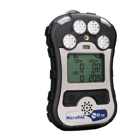
MicroRAETM
QuickStart Guide
WARNINGS
Read Before Operating
TheMicroRAE User’s Guide must be carefully read by
all individuals who have orwill have the responsibility
ofusing, maintaining, orservicing thisproduct. The
product will performas designedonly if it is used,
maintained, andservicedinaccordance with the manu-
facturer’s instructions.
CAUTION!
Neveroperate the monitor when the rear coverisre-
moved. Remove rear cover, sensors, and/or batteryor
chargethe batteryonly inanareaknown tobe non-
hazardous. Never use the instrument withthe calibration
adapterinstalled,asthiscancausedistortedreadings,a
potentialsafetythreat.
User Interface
Functions are controlled via the [MODE] and [Y/+]
keys. The display shows information such as
monitored threats, real-time readings and measure-
ment units, alarm type (when inalarm, including cal.
overdue), battery status, datalog (if on), GPS status,
and radio and connection quality (if available).
Turning The MicroRAE On
With the instrument turned off, press andhold the
[MODE] key until the audible alarm stops,and then
release.During startup,it teststhebattery,buzzer,
vibration alarm, LEDs, andinternalfunctions.Thenthe
main readingscreen is shown.
Note: If thebatteryiscompletelyempty,thenthe
display briefly shows the message “LowBattery,” and
theMicroRAEshuts off.Youshouldchargethe battery
beforeturningit onagain.
Note:It takes 45 seconds for some sensors to show
a reading, so if any have not warmed up by the
time the main screen is shown, you will see “- -”
instead of a numerical value.
Note: If Fast Startup is enabled on the instrument,
fewer screens are shown during startup, compared
to Normal Startup sequence.
Charging The MicroRAE
Always fullychargethe battery before use. Contacts on
the bottom of the MicroRAE meet the Travel Charger’s
or Charging Cradle’s contact pins, transferringpower.
Makesurethe chargerand MicroRAE arefirmly
attached. Then connect the AC Adapter’s plug to the
charger,andplugitstransformer intoanACoutlet.
While charging, the LED on thecradle glows red.When
the battery isfully charged, the LED glows green.
Turning The MicroRAE Off
Pressandhold [MODE]. A5-secondcountdownto shut-
offbegins.Youmustcontinuepressingonthekeyforthe
entireshutoffprocess.Ifyouremoveyourfingerfromthe
keyduringthecountdown,theshutoffoperationis
canceledandtheMicroRAE continues normal operation.
When the countdown ends and the screen displays “Unit
Off,” release your finger from the [MODE] key. The
MicroRAEisnowoff.
Testing The Alarms
Under normal-operation mode and non-alarm condi-
tions, the buzzer, vibration alarm, and LEDcan be
tested anytime by pressing [Y/+] once. If any alarm
does not respond, check the Alarm Settings in
Programming Mode or in ProRAE Studio II to make
sure all alarms are enabled. If any alarms are enabled
but are not functional, do not use the instrument.
Phone: 408-952-8200 Fax: 408-952-8480
Email: RAE-[email protected]m
www.raesystems.com
RAE Systems by Honeywell
3775 N. First St.
San Jose, CA 95134-1708 USA
AC Adapter
Plug
Cable from
AC adapter
Charger
Charging
status LED
LEDs
LEDs
Alarm
Buzzer
[MODE] key
[Y/+] key
Gas
Inlets
Gas
Inlets
Charging and
Communication
Contacts on bottom
Display
[N/-] key
Alarm
Buzzers
LEDs
[Y/+] key
Charging and
Communication
Contacts
[Y/+] key[Y/+] key
Bump Testing and Calibration Setup
Important! Test the alarms prior to performing a
bump or span calibration test.
Manuallycalibrate the MicroRAEusing afixed-flow
regulator(refer to User’s Guide for moredetails)andthe
suppliedspecialcalibrationadapterthatcoversthe gas
inlet:
1. Connectthegascylinder,flowregulator,tubing,and
calibrationadapter totheMicroRAE.
2. With the MicroRAE in Normal Mode, enter
ProgrammingModebypressingandholding both
[MODE]and[Y/+] until thepassword screen
appears.
3.Input the 4-digit password. (The default password is
“0000”.)Thenfollowthe menusto selectsingle-or
multi-sensor bumptest,zero,orspancalibration.
Important!Aftera bumptestor calibration, removethe
calibrationadapter toensurecorrectreadings.
Bump (Functional) Testing
Bump test toconfirm that the sensors and alarms are
functional.
Important! Make sure all sensors have warmed up
before performing the bump test.
With the MicroRAE in Programming Mode:
1.Enter the BumpTest or Multi Bump menu. The
calibration gas value for each sensor is shown.
2.In Single Bump, select the sensor to bump test. In
Multi Bump, you do not need to select a sensor.
3.Connect calibration gas to the instrument and start
the flow.
4.Press [Y/+] to start the bump test.
5.After the countdown, the result is shown.
6.Exit bump testing.
Zero & Fresh Air Calibration
Before othercalibrations are performed, the MicroRAE
should be fresh-air calibrated in clean air with 20.9%
oxygen or with a cylinder of clean zero air. The oxygen
sensorshould be calibrated withnitrogen (N2). In
Programming Mode, select “Fresh Air.” Then:
Press [Y/+]tostart a FreshAircalibrationforthelisted
sensors. All are fresh-aircalibratedat once.
Toindividuallyzero calibratesensors:
1. Select “SINGLE ZERO” and select a sensor.
2. Press[Y/+] to select a sensor to zero calibrate.
3. Start the flow of the zero gas, if used, and press
[Y/+].
4. The screen says, “CAL” and counts down.
5. When done, it says, “PASS” (the reading should be
0 or very close to it for combustible and toxic gas
sensors, and 0% Vol. for an oxygen sensor).
6. Shut off the flow of zero air (if used) and remove
the calibration adapter.
Span Calibration
SpanCalibrationdetermines the second point of the
sensor calibration curve for the sensor.
Important! Make sure all sensors have warmed up
before performing a span calibration.
With the MicroRAE in Programming Mode:
1.Enter the Single Span or Multi Span menu. The
calibration gas value for each sensor is shown.
2.In Single Span, select the sensor to calibrate. In
Multi Span, you do notneed to select a sensor.
3.Connect calibration gas to theinstrument and start
the flow.
4.Press [Y/+] to start calibration.
5.After the countdown, the result is shown.
6.Exit span calibration.
Rev. A P/N: M03-4002-000
Menu Navigation
Pressing [MODE] repeat-
edly allows you to step
through the screens as
shown here.
Note: The gray boxes
Indicate optional func-
tions. These depend on
the instrument’s config-
uration and settings.
Consult the MicroRAE
User’s Guide for more
detailed descriptions.

Other manuals for microrae

1

Other Rae Measuring Instrument manuals

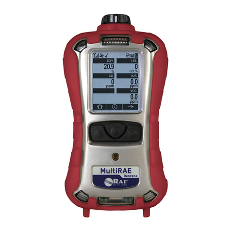
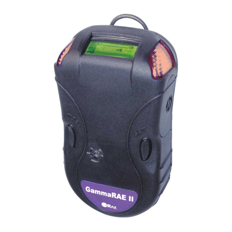
Rae GammaRAE II Responder User manual

Rae

Rae GammaRAE II Responder User manual

Rae UltraRAE PGM-7200 User manual

Rae

Rae UltraRAE PGM-7200 User manual

Rae AutoRAE Lite User manual

Rae

Rae AutoRAE Lite User manual

Rae IAQRAE PGM-5210 Manual

Rae

Rae IAQRAE PGM-5210 Manual

Rae ToxiRAE Pro User manual

Rae

Rae ToxiRAE Pro User manual

Rae UltraRAE 3000 User manual

Rae

Rae UltraRAE 3000 User manual

Rae AreaRAE Installation guide

Rae

Rae AreaRAE Installation guide

Rae MiniRAE Lite User manual

Rae

Rae MiniRAE Lite User manual

Rae MiniRAE 2000 PGM-7600 User manual

Rae

Rae MiniRAE 2000 PGM-7600 User manual

Rae Q-RAE User manual

Rae

Rae Q-RAE User manual

Rae ppbRAE 3000 User manual

Rae

Rae ppbRAE 3000 User manual

Rae QRAE 3 User manual

Rae

Rae QRAE 3 User manual

Rae ppbRAE 3000 User manual

Rae

Rae ppbRAE 3000 User manual

Rae microrae User manual

Rae

Rae microrae User manual

Rae MeshGuard User manual

Rae

Rae MeshGuard User manual

Rae TN-204 User manual

Rae

Rae TN-204 User manual

Rae UltraRAE 3000 Assembly instructions

Rae

Rae UltraRAE 3000 Assembly instructions

Rae ToxiRAE Pro PID User manual

Rae

Rae ToxiRAE Pro PID User manual

Rae MultiRAE Plus PGM-50/4 User manual

Rae

Rae MultiRAE Plus PGM-50/4 User manual

Rae VRAE PGM-7800 User manual

Rae

Rae VRAE PGM-7800 User manual

Rae GammaRAE II Installation guide

Rae

Rae GammaRAE II Installation guide

Rae GammaRAE II User manual

Rae

Rae GammaRAE II User manual

Rae DoseRAE 2 User manual

Rae

Rae DoseRAE 2 User manual

Rae DoseRAE 2 User manual

Rae

Rae DoseRAE 2 User manual

Popular Measuring Instrument manuals by other brands

Rigol DSA1000 Series Accessories User Guide

Rigol

Rigol DSA1000 Series Accessories User Guide

AlphaLab TriField EM100 quick start guide

AlphaLab

AlphaLab TriField EM100 quick start guide

Hioki L2003 user manual

Hioki

Hioki L2003 user manual

DANOPLUS DP-101 user manual

DANOPLUS

DANOPLUS DP-101 user manual

Eleaf LCD Meter user manual

Eleaf

Eleaf LCD Meter user manual

Megger TM1700 Series user manual

Megger

Megger TM1700 Series user manual

BIOS dry-cal dc-lite user manual

BIOS

BIOS dry-cal dc-lite user manual

Megaimpulse NRG1001 user manual

Megaimpulse

Megaimpulse NRG1001 user manual

IET Labs 1565-E User and service manual

IET Labs

IET Labs 1565-E User and service manual

ICS Schneider Messtechnik GA35 operating instructions

ICS Schneider Messtechnik

ICS Schneider Messtechnik GA35 operating instructions

Carel boss micro BMBST00DP0 Hardware guide

Carel

Carel boss micro BMBST00DP0 Hardware guide

Powerfix Profi Z22855 Operation and safety notes

Powerfix Profi

Powerfix Profi Z22855 Operation and safety notes

LIMIT 7000 operating manual

LIMIT

LIMIT 7000 operating manual

Sierra HART 600 Series instruction manual

Sierra

Sierra HART 600 Series instruction manual

Sensor Electronics AirDistSys 5000 Operator's manual

Sensor Electronics

Sensor Electronics AirDistSys 5000 Operator's manual

Kessel SonicControl Installation, operation and maintenance instructions

Kessel

Kessel SonicControl Installation, operation and maintenance instructions

TESTO 557 quick start guide

TESTO

TESTO 557 quick start guide

Endress+Hauser Proline Prowirl D 200 Brief operating instructions

Endress+Hauser

Endress+Hauser Proline Prowirl D 200 Brief operating instructions

manuals.online logo
manuals.online logoBrands
  • About & Mission
  • Contact us
  • Privacy Policy
  • Terms and Conditions

Copyright 2025 Manuals.Online. All Rights Reserved.