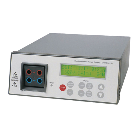
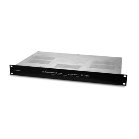
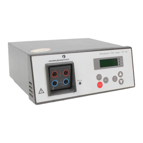
GE EPS 301 User manual

Electrophoresis Power Supply
EPS 301
GE Healthcare
User Manual
Manuel d’Utilization
Bedienungsanleitung
Manual del usuario
Manuale dell’operatore

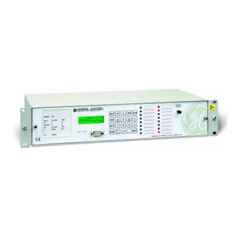
Fig 1. The front panel of the EPS 301.
Fig 1. Le panneau avant de l’EPS 301.
Abb 1. Die Fronttafel des EPS 301.
Fig 1. Panel frontal de la EPS 301.
Fig 1. Pannello anteriore dell’EPS 301.
Fig 2. The rear panel of the EPS 301.
Fig 2. Le panneau arrière de l’EPS 301.
Abb 2. Die Rückwand des EPS 301.
Fig 2. Panel posterior de la EPS 301.
Fig 2. Pannello posteriore dell’EPS 301.
100-120 220-240
Voltage
Frequency
Power
100-120/220-240 V AC
50/60 Hz
120W 1.5 A MAX
Certified in accordance with IEC 1010-1
by SEMKO AB, Sweden
MAINS
Disconnect before servicing
HV on
Electrophoresis Power Supply - EPS 301
view
STOP
run
set
enter

Important user information
All users must read this entire manual to fully understand the
safe use of EPS 301.
WARNING!
The WARNING! sign highlights instructions that must
be followed to avoid personal injury. It is important
not to proceed until all stated conditions are met and
clearly understood.
CAUTION!
The CAUTION! sign highlights instructions that must be followed
to avoid damage to the product or other equipment. It is
important not to proceed until all stated conditions are met and
clearly understood.
Note
The Note sign is used to indicate information important for
trouble-free and optimal use of the product.
CE Certifying
This product meets the requirements of applicable CE-directives.
A copy of the corresponding Declaration of Conformity is
available on request.
The CE symbol and corresponding declaration of conformity, is
valid for the instrument when it is:
– used as a stand-alone unit, or
– connected to other CE-marked GE Healthcare instruments, or
– connected to other products recommended or described in
this manual, and
– used in the same state as it was delivered from GE Healthcare
except for alterations described in this manual.
Recycling
This symbol indicates that the waste of electrical
and electronic equipment must not be disposed
as unsorted municipal waste and must be
collected separately. Please contact an authorized
representative of the manufacturer for information
concerning the decommissioning of your equipment.
ITALIANOESPAÑOLDEUTCHFRANCEENGLISH ITALIANOESPAÑOLDEUTCHFRANCEENGLISH
Safety Standards
This product meets the requirement of the Low Voltage Directive
(LVD) 73/23/EEC through the following harmonized standards:
• EN 61010-1
• IEC 61010-1
• CAN/CSA-C22.2 No. 61010-1
• UL61010-1
EMC Standards
This device meets the requirements of the EMC Directive 89/336/
EEC through the following harmonized standards:
• EN 61326 (emission and immunity)
• EN 55011, GR 1, Class A (emission)
• This device complies with part 15 of the FCC rules (emission).
Operation is subject to the following two conditions:
1 This device may not cause harmful interference.
2 This device must accept any interference received,
including interference that may cause undesired
operation.
4Electrophoresis Power Supply EPS 301 User Manual 18-1130-18 Edition AC
ENGLISHFRANCEDEUTCHESPAÑOLITALIANO
Contents
ENGLISHFRANCEDEUTCHESPAÑOLITALIANO
Contents
1 Introduction
2 Safety information
2.1 Safety precautions........................................................................................................................ 6
2.2 Built-in safety features................................................................................................................ 6
3 Unpacking and installation
3.1 Unpacking ......................................................................................................................................... 7
3.2 Mains connection........................................................................................................................... 7
3.3 Connection of the electrophoresis unit(s)........................................................................... 7
4 Technical description
4.1 Materials............................................................................................................................................. 9
4.2 Front panel........................................................................................................................................ 9
4.3 Display................................................................................................................................................. 9
4.4 Keyboards ......................................................................................................................................... 9
4.5 Output sockets ..............................................................................................................................10
4.6 Rear panel .......................................................................................................................................10
5 Operation
5.1 Connecting the electrophoresis unit(s) ..............................................................................11
5.2 Programming.................................................................................................................................11
5.3 Running.............................................................................................................................................11
5.4 Short instructions.........................................................................................................................12
6 Maintenance
6.1 Recycling..........................................................................................................................................14
7 Trouble shooting
7.1 Mains power failure ....................................................................................................................15
7.2 Serious error...................................................................................................................................15
7.3 Recycling..........................................................................................................................................15
8 Technical specifications
9 Ordering information

ITALIANOESPAÑOLDEUTCHFRANCEENGLISH
Introduction 1
5
Electrophoresis Power Supply EPS 301 User Manual 18-1130-18 Edition AC
The GE Healthcare Electrophoresis Power Supply EPS 301 is a high quality, high precision
and safe power supply for electrophoresis applications that require a maximum of
300 volts, 400 mA and 80 W.
EPS 301 is primarily designed for the following techniques:
1. Submarine DNA electrophoresis
2. Electroblotting
3. Immuno electrophoresis
4. Mini polyacrylamide gel electrophoresis
Electrophoresis separations can be controlled by voltage or current. The EPS 301
automatically switches over the controlling parameter according to programmed limits
and conductivity variations in the system.
Two electrophoresis units can be connected to the EPS 301 and run with the same
programmed method at one time.
1 Introduction

6Electrophoresis Power Supply EPS 301 User Manual 18-1130-18 Edition AC
2 Safety information
ENGLISHFRANCEDEUTCHESPAÑOLITALIANO
2.1 Safety precautions
WARNING! Because this instrument can develop sufficient voltage and current to
produce a lethal shock, extreme caution should be exercised in its operation.
The power supply should only be used by properly trained operators. Read this entire
manual before using this power supply and use only according to the manufacturer’s
instructions.
1. This instrument is designed for indoor use only.
2. The instrument must always be used with the earth lead of the power cord correctly
grounded to earth at the mains outlet.
3. To permit sufficient cooling, ensure that the vents in the rear and sides of the
instrument are not covered.
4. Do not operate the instrument in extreme humidity (above 95%). Avoid
condensation by letting the unit equilibrate to ambient temperature when taking
the power supply from a colder to a warmer environment.
5. Keep the instrument as dry and clean as possible. Wipe regularly with a soft damp
cloth. Let the power supply dry completely before use. If wetted, unplug the power
supply until the instrument is dry.
6. Use only undamaged electrical wire and equipment specified for the voltages you
will use. High voltage electrical wires should be in accordance with IEC 1010-2-
031:1993. All equipment connected to high voltage should be in accordance with
IEC 1010-1:1993.
2.2 Built-in safety features
The EPS 301 has been tested and complies with the IEC 61010-1 (EN 61010-1) electrical
safety standard.
2 Safety information

ITALIANOESPAÑOLDEUTCHFRANCEENGLISH
Unpacking and installation 3
7
Electrophoresis Power Supply EPS 301 User Manual 18-1130-18 Edition AC
3.1 Unpacking
Check the contents against the packing list supplied. Inspect for any damage that may
have occurred during transit. Report any damage immediately to your local
GE Healthcare representative and to the transport company concerned.
3.2 Mains connection
Select the appropriate voltage range, 100–120 or 220–240 V. See fig 2 inside front cover.
WARNING! If the power supply is connected to 220–240 V with the range set to
100–120 V, the instrument can be severely damaged.
WARNING! Only use mains cables delivered or approved by GE Healthcare.
WARNING! Do not block the rear panel of the system. The mains power switch must
always be easy to access.
Select the appropriate mains cable and connect one end to the mains socket on the
EPS 301 power supply, see fig 2 inside front cover, and the other end to an AC grounded
outlet.
Switch on the power. Each time the instrument is turned on a self diagnostic test is done.
If an error is detected during the test a message will appear on the display and an alarm
will sound.
3.3 Connection of the electrophoresis unit(s)
Connect the leads from the electrophoresis unit (red to red, and black or blue to blue).
The red lead is the positive and black or blue is the negative.
WARNING! Use only undamaged electrical cables and equipment approved for the
voltage you will use. High voltage electrical cables should be in accordande with
IEC 1010–2–031:1993. All equipment connected to high voltage electrical cables
should be in accordance with IEC 1010-1:1993.
3 Unpacking and installation

8Electrophoresis Power Supply EPS 301 User Manual 18-1130-18 Edition AC
3 Unpacking and installation
ENGLISHFRANCEDEUTCHESPAÑOLITALIANO
Local regulation for Great Britain
IMPORTANT WARNING
This appliance must be earthed.
The wires in the mains lead are coloured in accordance with the following code:
Green and yellow Earth
Blue Neutral
Brown Live
If the plug provided is unsuitable for your socket outlets, the plug must be cut off
and a suitable plug fitted. The cut-off plug should be disposed of and must not be
inserted into any socket as this can result in electric shock. The plug or adapter or
the distribution panel should be provided with a 13 amp fuse. As the colours of the
wires in the mains lead of this appliance may not correspond with coloured markings
identifying the terminals in your plug, proceed as follows:
The green and yellow wire must be connected to the terminal in the plug which is
marked with the letter E or by the earth symbol, or coloured green, or green and
yellow.
The blue wire must be connected to the terminal which is marked with the letter N or
coloured black.
The brown wire must be connected to the terminal which is marked with the letter L
or coloured red.
Note: After replacing or changing a fuse, the fuse cover in the plug must be replaced
with a fuse cover which corresponds to the colour of the insert in the base
of the plug or the word that is embossed on the base of the plug, and the
appliance must not be used without a fuse cover.
Only 13 Amp fuses approved to B.S. 1362 A.S.T.A. should be used.

ITALIANOESPAÑOLDEUTCHFRANCEENGLISH
Technical description 4
9
Electrophoresis Power Supply EPS 301 User Manual 18-1130-18 Edition AC
4.1 Materials
The main components in the EPS 301 power supply are made of the following materials.
Instrument box Aluminium
Display holder Polypropene (PP). UL94V0
Keyboard Polyester
Output sockets Acetalplastic (POM). UL94V0
Rubber feet Polyurethane
4.2 Front panel
On the front panel there is a numerical display illustrated with the symbols, V, mA, and
h.m., a keyboard with six membrane keys, a light emitting diode that lights when voltage
is applied (HV on) and output sockets for two electrophoresis units.
4.3 Display
A four digit numeric display guides you through the programming, shows actual
parameter values during the electrophoresis and final parameter values afterwards. It
also shows error messages.
Figure 1, inside front cover, shows the display in the End position when power is switched
on.
4.4 Keyboards
SET/ENTER
Puts the instrument into its program mode. Pressing SET/ENTER in the program mode
enters a value, if valid, and moves the program to the next parameter.
In the RUN mode, pressing SET/ENTER allows you to make changes in the program
during a run.
Valid values are: voltage 5–300 V, current 10–400 mA, time 0.01–23.59 h, or timer
off - - - -.
UP/DOWN
Changes the parameter value V, mA, and h.m. when the display is flashing. Numerical
values are changed in an accelerating manner when the key is held down. Clicking /
changes the value in pre-set increments. The values will automatically change from
maximum to minimum value or vice versa, except for the time (h.m.) where the
signs - - - - are placed between the minimum and maximum values indicating that the
timer is switched off.
4 Technical description
set
enter
/

10 Electrophoresis Power Supply EPS 301 User Manual 18-1130-18 Edition AC
4 Technical description
ENGLISHFRANCEDEUTCHESPAÑOLITALIANO
RUN
Starts the run and puts the program into RUN mode. The light (HV on) is switched on.
VIEW
In run mode, VIEW switches between the actual values for voltage, current and elapsed
time. Pressing VIEW for more than three seconds starts automatic switching between the
actual values for voltage, current and elapsed time. This automatic switching is stopped
by pressing VIEW or RUN.
In End mode, VIEW switches between the end parameter values.
STOP
Stops the run and puts the instrument in End mode. The voltage and the light (HV on) are
switched off. By pressing VIEW the end parameter values are displayed.
4.5 Output sockets
There are two sets of output sockets connected in parallel to allow two electrophoresis
units to be connected and run at the same time, see fig. 1 inside front cover.
4.6 Rear panel
The rear panel is shown in fig 2, see inside front cover. On the rear panel there is:
1. A mains switch. Press in I to switch on the power to the power supply. Press 0 to
switch off the power.
2. A socket for the mains cable.
3. A switch for voltage range. The left position corresponds to 100–120 V and the right
to 220–240 V.
4. Vents.
run
view
STOP

ITALIANOESPAÑOLDEUTCHFRANCEENGLISH
11
Electrophoresis Power Supply EPS 301 User Manual 18-1130-18 Edition AC
Operation 5
5.1 Connecting the electrophoresis unit(s)
Connect the leads from the electrophoresis unit (red to red, and black or blue to blue).
Red is positive and black or blue negative. Two electrophoresis units can be run at the
same voltage simultaneously. When two electrophoresis units are run at the same time,
double the current. Voltage will be the same whether one or two units are run.
5.2 Programming
Programming
Enter the program mode by pressing SET/ENTER. When the display is flashing and one of
the parameters V, mA or h.m. is lit, the program is ready for setting the values by using
the /buttons.
Confirm and go to the next parameter by pressing SET/ENTER.
Pressing STOP in program mode saves the displayed value and puts the program in End
mode. When the EPS 301 power supply is switched on, the programmed values from the
last run can be used directly by pressing run.
Set limits for voltage, current and time
The flashing display and the lighted symbol V indicates that the voltage limit can be set.
Using the /buttons, select the maximum voltage desired for the run. Confirm with
SET/ENTER. Repeat the same procedure to set current and time limits. If no time limit is
used, switch the timer off by setting the time to zero. This is indicated by - - - -. Confirm
with SET/ENTER. Programmable values are: voltage, 5-300 V, current, 10-400 mA, time,
0.01-23.59 h or timer off (- - - -).
Alarm
When the programmed time has elapsed, the program will enter the End mode and the
alarm will sound. You can stop the alarm by pressing any key. The timer and alarm are
switched off by adjusting the time to zero.
5.3 Running
Run
Press RUN to start the electrophoresis. A light emitting diode shows when voltage is
applied (HV on). The display will show one of the actual values. If no current is displayed,
please check the electrical connections to the electrophoresis equipment.
View actual values
Press VIEW in Run mode to change between the actual values for voltage, current or
elapsed time. Press VIEW for more than three seconds to switch automatically between
these values. Stop the automatic switching by pressing VIEW or RUN.
5 Operation

12 Electrophoresis Power Supply EPS 301 User Manual 18-1130-18 Edition AC
ENGLISHFRANCEDEUTCHESPAÑOLITALIANO
5 Operation
View programmed values
Press SET/ENTER to view the programmed values during a run. If the keyboard is idle for
4 seconds or you press RUN the display goes back to the actual values.
Change parameters during a run
When the method is running, changes can be introduced in the program by pressing
SET/ENTER and using /. Confirm by pressing SET/ENTER or RUN
Stop the run
When the programmed time has elapsed, the program will enter the End mode and the
alarm will sound. You can stop the alarm by pressing any key. It is also possible to break
the run manually by pressing STOP. In both cases, the values for voltage and current will
go to zero, as indicated by the light emitting diode switching off.
View end parameter values
Display the end parameter values by pressing VIEW.
Post electrophoresis
Disconnect the leads and proceed with post-electrophoretic techniques. Since the quality
of your separation will deteriorate due to diffusion, you should remove the gel and begin
staining or blotting immediately.
5.4 Short instructions
This section summarises the main points covered earlier in this chapter. Use it as a
check list once you are familiar with the detailed programming and running instructions.
Refer also to the separate short instruction EPS 301 included with the power supply. We
recommend you keep this separate short instruction close by the instrument.
1. Turn mains power ON. The program enters the End mode. If the programmed values
from the last run are to be used again, go to point 4 below. To change the program,
press SET/ENTER to enter the program mode. The voltage symbol V is lit and the
value for voltage flashes. The programmed value from the last run is displayed.
Use /to set to the desired voltage. Press SET/ENTER to confirm. If the voltage
value is correct from the beginning just press SET/ENTER to confirm.
2. The display shows the last programmed value for current flashing. Press /until
the desired value is reached. Confirm by pressing SET/ENTER.
3. The value for time is now flashing. Use /to set the time. To switch off the timer,
set the time to zero. Indicated by - - - -. Confirm by pressing SET/ENTER.
4. When programming is completed, connect your electrophoresis unit to the output(s),
and press RUN.
5. Press VIEW to display actual voltage, current and elapsed time. Press VIEW for
more than three seconds to start automatic switching of actual values.
6. Press SET/ENTER during the run to check the programmed parameters and change
the values by pressing /. Confirm by SET/ENTER.
7. The program stops automatically on completion or on STOP being pressed.
8. Press VIEW after the run to check the end parameters.

ITALIANOESPAÑOLDEUTCHFRANCEENGLISH
13
Electrophoresis Power Supply EPS 301 User Manual 18-1130-18 Edition AC
Operation 5
run
STOP
view
set
enter
view
view
view
view
view
view 1.05
28
120
End
0.23
40
120
1.05
400
120 V
mA
h.m.
V
mA
h.m.
V
mA
h.m.
set
enter
set
enter
set
enter
1. Set voltage limit.
5–›200 V
2. Set current limit.
10–›400 mA
3. Set tim 0.01–23.59 h.
(timer OFF=- - - -)
4. Start the run
5. View voltage, current
and elapsed time.
6. Stop the run
automatically or
manually.
7. View end parameters.
View and step by
Step by
Start by
Select by Confirm and
Step by
Confirm and
Step by
Confirm and
Step by
Select by
Select by
Enter
program
mode by
0
.
2
3
E
n
d
1
2
0
28
1
.05
40
1
2
0
1
.05
400
12
0
Fig 3. Step-by-step summary of programming and running.

14 Electrophoresis Power Supply EPS 301 User Manual 18-1130-18 Edition AC
ENGLISHFRANCEDEUTCHESPAÑOLITALIANO
6 Maintenance
Wipe the instrument regularly with a damp cloth. Let the instrument dry completely
before use. All servicing should be entrusted to qualified personnel only. Please contact
your local GE Healthcare representative for more service information.
6.1 Recycling
This symbol indicates that the waste of electrical and electronic equipment must not
be disposed as unsorted municipal waste and must be collected separately. Please
contact an authorized representative of the manufacturer for information concerning the
decommissioning of your equipment.
6 Maintenance

ITALIANOESPAÑOLDEUTCHFRANCEENGLISH
15
Electrophoresis Power Supply EPS 301 User Manual 18-1130-18 Edition AC
Trouble shooting 7
If an error occurs, either during a run or when switching on the power supply, the
output is switched off if necessary and an error message will be displayed. The following
messages can be displayed.
7.1 Mains power failure
The program continues when power is resumed. The display switches between PF and
the actual parameter value. The message -PF- is removed by pressing any key. No
special action is needed.
7.2 Serious error
If a serious error occurs, the program enters the FAIL mode. The output is switched off
and FAIL is shown in the display.
Please contact your GE Healthcare representative.
7.3 Recycling
This symbol indicates that the waste of electrical and electronic equipment must not
be disposed as unsorted municipal waste and must be collected separately. Please
contact an authorized representative of the manufacturer for information concerning the
decommissioning of your equipment.
7 Trouble shooting
-PF-
FAIL

16 Electrophoresis Power Supply EPS 301 User Manual 18-1130-18 Edition AC
ENGLISHFRANCEDEUTCHESPAÑOLITALIANO
8 Technical specifications
Regulation Maximum voltage and current with automatic cross-over
at preset limits
Output mode Contante Voltage: 0–300 V DC,
Contante Current: 0–400 mA
Maximum Power Output 80 W
Programming range Voltage: 5–300 V DC
Current: 10–400 mA
Time: 00.01–23.59 h or off (- - - -)
Output resolution Voltage: 1 V
Current: 1 mA
Programming resolution Voltage: 1 V
Current: 1 mA
Time: 1 min
Accuracy Voltage: 4%, ± 2 V
Current: 4%, ± 4 mA
Timer: 0.1% ± 1 min
Line regulation < 0.5%
Load regulation < 1% at load change 10–90% of maximum load
Ripple < 3% at 300 V
Short term stability < 0.2% /10 h after warm up
Long term stability < 1% /year
Output protection Fully protected against any overload conditions
Recovery after power failure The program continues automatically
Ambient operating temperature 4–40 °C
Ambient operating humidity 0–95%
Ambient operating pressure 68–106 kPa, maximum altitude of 2000 m
Mains requirements 100–120 V/220–240 V; 50/60 Hz
Power consumption Max 120 W
Dimensions (WxDxH) 250 x 215 x 95 mm
Weight 3.0 kg
8 Technical specifications

ITALIANOESPAÑOLDEUTCHFRANCEENGLISH
17
Electrophoresis Power Supply EPS 301 User Manual 18-1130-18 Edition AC
Ordering information 9
Designation Code No.
Electrophoresis Power Supply – EPS 301 18-1130-01
9 Ordering information


ITALIANOESPAÑOLDEUTCHFRANCEENGLISH ITALIANOESPAÑOLDEUTCHFRANCEENGLISH
Renseignements importants d’utilisation
Veuillez lire manuel entièrement pour une compréhension totale
de l’usage de EPS 301.
AVERTISSEMENT!
Le signe d’avertissement souligne une instruction
qui doit être scrupuleusement suivie afin d’éviter des
blessures corporelles. Ne pas poursuivre tant que
les instructions n’ont pas été entièrement assimilées
et que toutes les conditions indiquées n’ont pas été
réunies.
PRECAUTION!
Le signe de précaution est utilisé pour attirer l’attention sur
les instructions ou conditions devant être suivies, afin d’éviter
d’endommager le produit ou autre équipement. Ne pas
poursuivre tant que les instructions n’ont pas été entièrement
assimilées et que toutes les conditions indiquées n’ont pas été
réunies.
Remarque
Le symbole « Remarque » sert à indiquer des informations
importantes pour une utilisation sans problème et optimale du
produit.
Certification CE
Ce produit est conforme aux exigences des directives CE
applicables.
Une copie de la Déclaration de conformité correspondante est
disponible sur demande.
Le symbole CE et la déclaration de conformité correspondante
sont valides pour l’instrument lorsque celui-ci est :
– utilisé comme unité autonome, ou
– connecté à d’autres instruments de santé portant la marque
CE, ou
– connecté à d’autres produits recommandés ou décrits dans
le présent manuel, et
– utilisé dans le même état que celui dans lequel il a été fourni
par GE Healthcare hormis les modifications décrites dans le
présent manuel.
Recyclage
Ce symbole indique que les déchets relatifs à
l’équipement électrique et électronique ne doivent
pas être jetés comme les ordures ménagères non-
triées et doivent être collectés séparément. Contactez
un représentant agréé du fabricant pour obtenir
des informations sur la mise au rebut de votre
équipement.
Normes de securité
Ce produit répond aux exigences de la directive sur les basses
tensions (LVD) 73/23/CEE par le biais des normes harmonisées
suivantes:
• EN 61010-1
• IEC 61010-1
• CAN/CSA-C22.2 No. 61010-1
• UL61010-1
Normes CEM
Cet appareil répond aux exigences de la directive CEM 89/336/
CEE par le biais des normes harmonisées suivantes:
• EN 61326 (émission et immunité)
• EN 55011, GR 1, Classe A (émission)
• Cet appareil est conforme à la partie 15 de la réglementation
FCC (émission). Le fonctionnement est soumis aux deux
conditions suivantes:
1 Cet appareil ne peut pas causer d’interférence nocive.
2 Cet appareil doit accepter toute interférence reçue, y
compris celles pouvant entraîner un fonctionnement
indésirable.

2Electrophoresis Power Supply EPS 301 Manuel d’Utilization 18-1130-18 Edition AC
ENGLISHFRANCEDEUTCHESPAÑOLITALIANO
Table des matières
Table des matières
ENGLISHFRANCEDEUTCHESPAÑOLITALIANO ENGLISHFRANCEFRANCEESPAÑOLITALIANO
1 Introduction
2 Renseignements concernant la sécurité
2.1 Précautions....................................................................................................................................... 4
2.2 Caractéristiques de sécurité intrinsèques.......................................................................... 4
3 Reception et installation
3.1 Réception........................................................................................................................................... 5
3.2 Branchement sur l’alimentation secteur............................................................................ 5
3.3 Branchement d’unité(s) d’électrophorèse........................................................................... 5
4 Description technique
4.1 Panneau avant................................................................................................................................ 6
4.2 Ècran d’affichage........................................................................................................................... 6
4.3 Clavier.................................................................................................................................................. 6
4.4 Prises (connecteurs) de sortie .................................................................................................. 7
4.5 Panneau arrière.............................................................................................................................. 7
4.6 Èquipements..................................................................................................................................... 7
5 Utilisation
5.1 Instructions simplifiées............................................................................................................................ 8
Other manuals for EPS 301
1
Table of contents
Languages:
Other GE Power Supply manuals

GE
GE Infinity S User manual

GE
GE RAK315D User manual

GE
GE Tetra GEPS12-60U-NA User manual

GE
GE EPS 601 User manual

GE
GE DEH-40417 Operating instructions

GE
GE Tetra GEPS24W-80M Manual

GE
GE Current Tetra GEPS12W-60 Manual

GE
GE Current Tetra GEPS12-25U-EU Manual

GE
GE GEPS12-25U-NA User manual

GE
GE Tetra Series User manual

GE
GE Tetra GEPS24-100U-GL User manual

GE
GE LED 55 CC 1.4A TBDL 1-10V User manual

GE
GE Tetra GEPS24-300U-GL User manual

GE
GE SERIES B 480 User manual

GE
GE Tetra GEXLPS21 User manual

GE
GE Tetra GEPS24-100U-GLX Manual

GE
GE Tetra GEPS24-180U User manual

GE
GE RAK3152 User manual

GE
GE Digital Energy User manual

GE
GE GEPS24-180U Manual