1
1. Introduction. . . . . . . . . . . . . . . . . . . . . . 2
2. Safety information . . . . . . . . . . . . . . . . . 2
2.1 Safety precautions . . . . . . . . . . . . . . 2
2.2 Built-in safety features . . . . . . . . . . . 2
3. Unpacking and installation. . . . . . . . . . . 3
4. Technical description . . . . . . . . . . . . . . . 4
4.1 Materials . . . . . . . . . . . . . . . . . . . . . 4
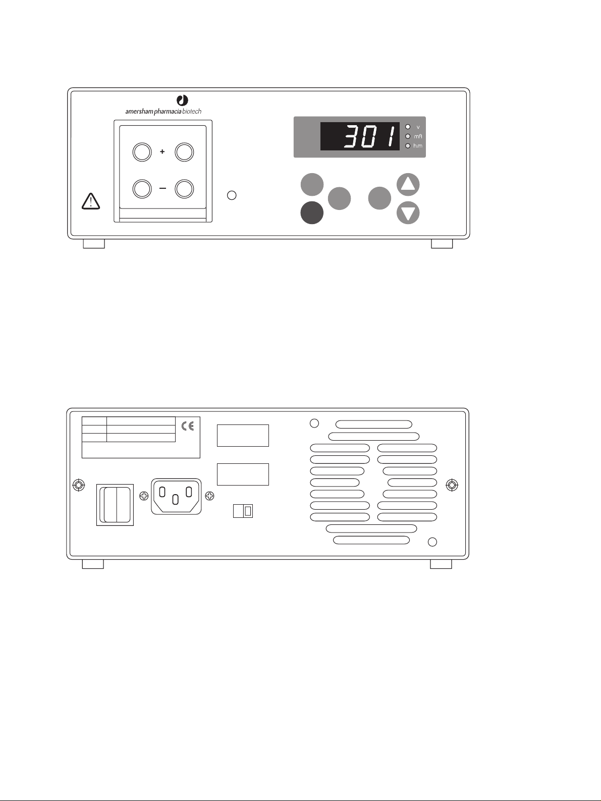
4.2 Front panel . . . . . . . . . . . . . . . . . . . 4
4.3 Display. . . . . . . . . . . . . . . . . . . . . . . 4
4.4 Keyboard. . . . . . . . . . . . . . . . . . . . . 4
4.5 Output sockets. . . . . . . . . . . . . . . . . 5
4.6 Rear panel . . . . . . . . . . . . . . . . . . . . 5
5. Operation. . . . . . . . . . . . . . . . . . . . . . . . 5
5.1 Connecting the . . . . . . . . . . . . . . . . .
electrophoresis unit(s) . . . . . . . . . . . 5
5.2 Programming. . . . . . . . . . . . . . . . . . 5
5.3 Running. . . . . . . . . . . . . . . . . . . . . . 5
5.4 Short instructions. . . . . . . . . . . . . . . 6
6. Maintenance . . . . . . . . . . . . . . . . . . . . . 8
7. Trouble shooting . . . . . . . . . . . . . . . . . . 8
8. Technical specifications . . . . . . . . . . . . . 9
9. Ordering information. . . . . . . . . . . . . . . 9
Contents
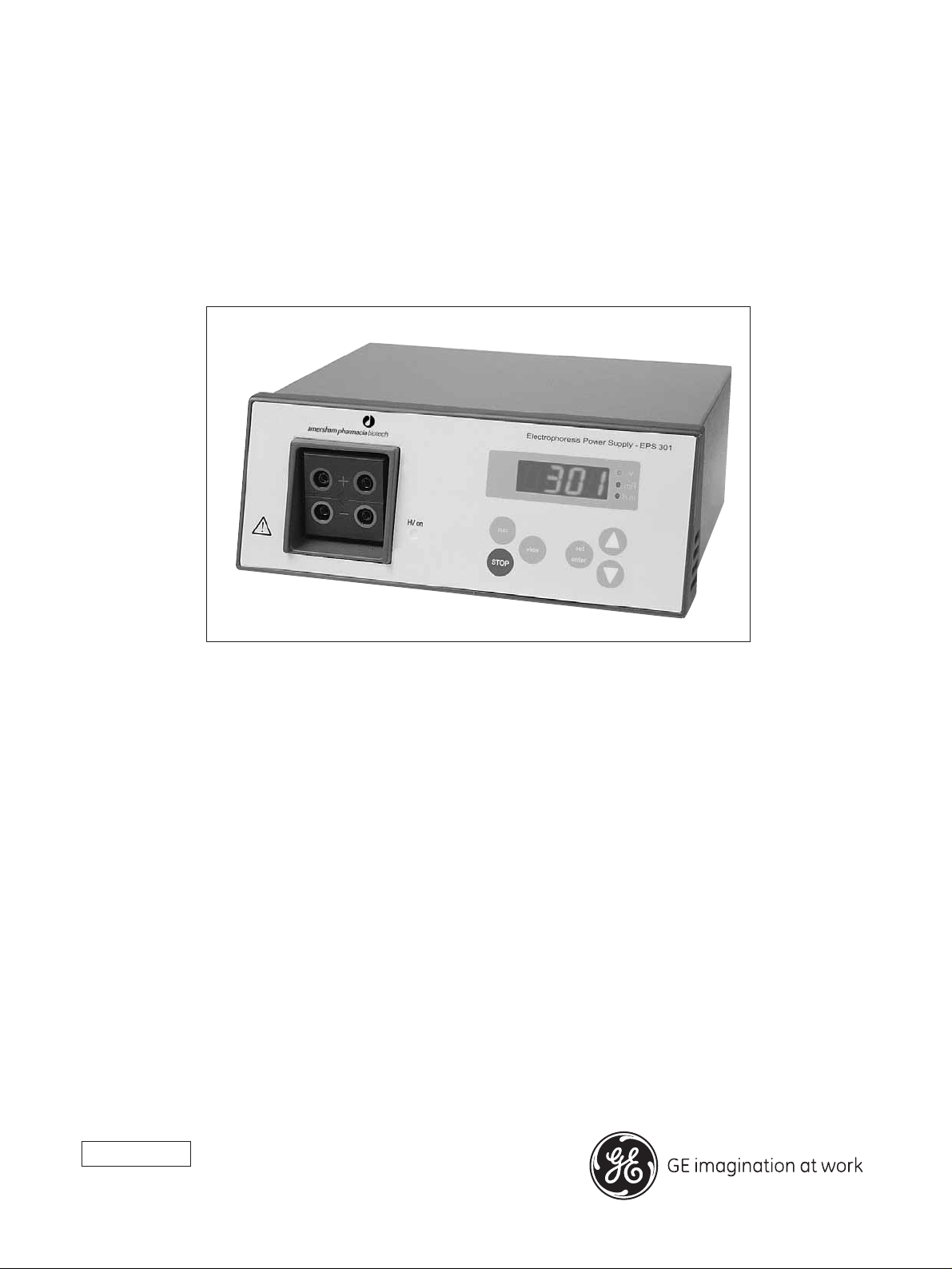
EPS 301 - User Manual
Please read this entire manual to
fully understand the safe use of
EPS 301
WARNING!
The Warning sign
highlights an instruction
that must be strictly
followed in order to
avoid personal injury. Be sure not to
proceeed until the instructions are
clearly understood and all stated
conditions are met.
Declaration of conformity
Safety Standards
This product meets the requirement
of the Low Voltage Directive (LVD)
73/23/EEC through the harmonized
standard EN 61010-1, 1993+ A1,
1992.
Important user information
EMC Standards
This product meets the requirement
of the EMC Directive 89/336/EEC
through the harmonized standards
EN 50081-1 (emission) and EN
50082-1 (immunity).
The CE symbol, and corresponding
declaration of conformity, is valid
for the instrument when it is.
– used as a “stand alone” unit or
– connected to other CE marked
GE Healthcare
instruments, or
– connected to other products
recommended or described in
this manual and
– is used in the same state as it was
delivered from GE Healthcare
except for alterations
described in this manual.
Terms and Conditions of Sale
All goods and services are sold
subject to the terms and conditions
of sale of the company within the
General Electric Company group which
supplies them. A copy of these terms
and conditions is available on
request.
Should you have any comments on
this product, we will be pleased to
receive them at:
Hoefer Biosciences Inc.
654 Minnesota Street
San Francisco, CA 94107 USA
Trademarks
GE Healthcare is a trademark of
General Electric Company.
Pharmacia and Drop Design are
trademarks of Pharmacia & Upjohn
Inc.
Office Addresses
GE Healthcare Bio-Sciences AB
SE-751 84 Uppsala
Sweden
GE Healthcare UK Ltd
GE Healthcare Place Little Chalfont
Buckinghamshire
England HP7 9NA
GE Healthcare Bio-Sciences Inc.
800 Centennial Avenue
P.O. Box 1327
Piscataway N.J. 08855-1327
USA