GE SuperBus 2000 User manual

466-2185 Rev. A (March 2005)
Copyright © 2005, GE Security Inc.
SuperBus 2000 2-Amp Power Supply • 600-1019
Installation Instructions
Description
The power supply provides an additional 12 VDC, 2 amps
(current limited) for Concord 4 system devices and is supervised
via the SuperBus®2000 digital data bus.
Note: For 24 hour backup, external power drain is limited to
95mA (during normal standby conditions) using a 4.5 Ah
battery, or 190mA continuous using a 7.0 Ah battery.
The power supply uses a 24 VAC, 50 VA power transformer. In
case of an AC power failure, a 12 VDC, 4.5 or 7 Ah backup
battery (not included) provides power to connected devices. The
battery is tested by the power supply on power up, every two
minutes afterward, and whenever the panel tests its own backup
battery.
The power supply also includes a hardwire zone input that
accepts normally open (NO) or normally closed (NC) intrusion
detection devices. The power supply can be located inside the
Concord 4/Concord Express V4 cabinet or it can be mounted in a
separate Concord Residential Enclosure (444-1700 and 444-1711
ordered as a separate kit) or Concord Commercial Expansion
Enclosure (444-1391 ordered as 60-816). See Mounting inside
panel cabinet on page 2, Mounting inside Concord residential
enclosure on page 2, and Mounting inside Concord Commercial
enclosure on page 3 for more information on mounting in a sepa-
rate enclosure.
Figure 1 describes the power supply main components.
Figure 1. Power supply main components
Installation
Use the following guidelines for installing the power supply.
Guidelines
• Up to 16 SuperBus 2000 devices can be connected to
Concord 4/Concord Express V4 panels (touchpads,
receivers, transceivers, HIMs, HOMs, ESMs, etc.).
• The power supply AC transformer must be plugged into an
AC outlet that is not a ground fault interrupt circuit (GFIC)
or controlled by a switch.
• When mounting the power supply inside the panel cabinet,
the backup battery can also be stored inside the panel
cabinet.
• When mounting the power supply in a separate enclosure,
the maximum wire length from the power supply bus and
power connections to the panel is 4,000 feet.
• When mounting the power supply in a separate enclosure,
the power supply mounting location should be determined
by the wire runs needed to provide power to devices with
minimal loss on the +12V OUT wire. Table 1 shows the
maximum wire runs between the power supply +12V OUT
terminal and the devices it will power.
• For UL installations, the +12V OUT is not fully supervised
for open circuits. Therefore, sirens cannot be connected
directly to the output.
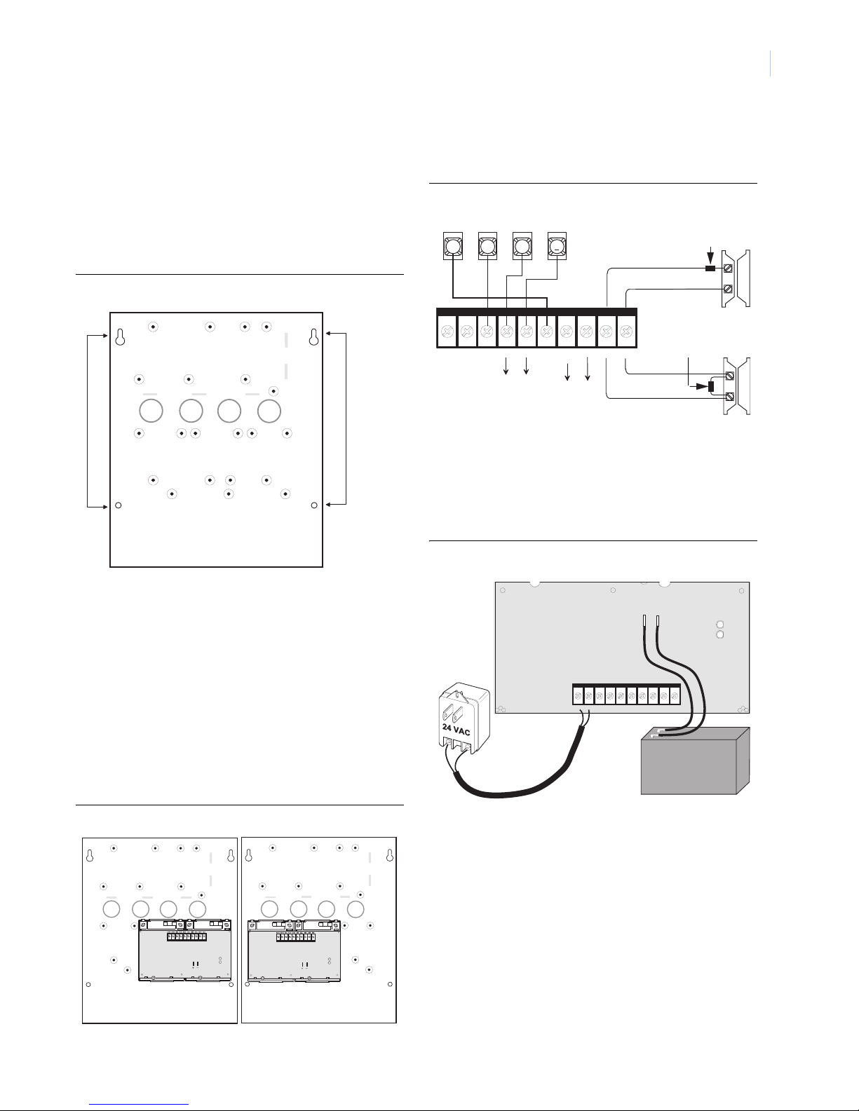
• For large installations with long wire runs, power supply
location is important. The total system wiring length (all
partitions) for all bus devices connected to a Concord 4/
Concord Express V4 panel must not exceed 4,000 feet. This
not only includes the power supply bus and power connec-
tions to the panel, but also any bus devices you may connect
to the power supply. For example, touchpads and other bus
devices in a remote partition should be connected to the
power supply rather than running the wires all the way to
the panel (Figure 2).
Figure 2. Bus device wiring example for remote partitions
Tools and Supplies
• 12 V backup battery (4.5 Ah part no. 60-681 or 7 Ah part
no. 60-680)
• Screwdrivers
• Separate enclosure—if not mounting power supply inside
panel cabinet
• Mounting screws
• Support Standoffs (included with panel)
• 4-conductor, 22- or 18-gauge stranded wire
• 2-conductor, 18-gauge wire (for AC transformer)
Mounting
Note: (A) Class 2, Class 3, and power-limited fire alarm circuits
must be installed using FPL, FPLR, FPLP, or substitute cable
2 4 V A C 2 4 V A C + 1 2 V B U S A B U S B G N D + 1 2 V
O U T
Z O N EG N D G N D
+_
Backup Red LED-bus
Terminal Strip
communication
Green LED-
power status
status
Battery
Connections
Table 1. Maximum +12V OUT wire length
Wire Gauge
Maximum wire length from power
supply +12V OUT terminal
22 100 feet
18 200 feet
16 350 feet
14 550 feet
CAUTION
CAUTION To prevent damaging the panel or power
supply, remove the panel AC power trans-
former and disconnect the backup battery
before installation.
You must be free of static electricity before
handling circuit boards. Wear a grounding
strap or touch a bare metal surface to
discharge static electricity.
+ 1 2 V B U S A B U S B G N D + 1 2 V
O U T
G N D
3456
+ 1 2 V AB
G N D B U S
Bus devices
connected to
panel Power
supply
Panel Bus devices
connected to
power supply

SuperBus 2000 2-Amp Power Supply
Installation Instructions
2
permitted by the National Electrical Code ANSI/NFPA 70.
Wire that extends beyond the cable jacket must be
separated from all other conductors by a minimum of 0.25
in. or by a nonconductive barrier.
OR
(B) Class 2, Class 3, and power-limited fire alarm circuit
conductors must be installed as Class 1 or higher circuits.
Mounting inside panel cabinet
1. Unplug the panel AC power transformer and disconnect the
backup battery.
2. Install the support standoffs (included with panel) at the
panel locations shown in Figure 3.
Figure 3. Installing panel support standoffs
3. Slide the top of the backplates onto the left and center
module mounting clips on the panel cabinet (Figure 4), then
snap the backplates on to the support standoffs (Detail in
Figure 4).
Figure 4. Mounting power supply inside panel cabinet
Mounting inside Concord residential enclosure
Note: This module is UL listed as a subassembly and must be
mounted in the same enclosure as the Concord 4 in UL
systems.
1. Unplug the panel AC power transformer and disconnect the
backup battery.
2. Place the cabinet at the desired location and mark the
cabinet mounting holes and knockouts (Figure 5).
Figure 5. Residential enclosure mounting holes and knockouts
3. Drill holes and insert the appropriate anchors where studs
are not present.
4. Run wires from all devices to be powered, to the power
supply.
5. Run a 4-conductor, 22-gauge or larger stranded wire from
the power supply to the panel.
6. Run a 2-conductor, 18-gauge stranded wire from the power
supply to the AC transformer location.
7. Feed all wires through the knockouts and secure the cabinet
to the wall with the included screws.
8. Remove the power supply circuit board from the plastic
mounting plates.
9. Position the plastic mounting plates in the cabinet on the
top-left or top-right side and secure them with the six self-
tapping screws included with the power supply (Figure 6).
Figure 6. Power supply mounting positions in residential enclosure (arrows
indicate screw locations)
10. Re-install the power supply circuit board on the plastic
mounting plates.
Mounting
Clips
Power Supply
on Backplates
Detail
Knockout Knockout
Cabinet
Mounting
Holes (4)

3
Mounting inside Concord Commercial enclosure
Note: This module is UL listed as a subassembly and must be
mounted in the same enclosure as the Concord 4 in UL
systems.
1. Unplug the panel AC power transformer and disconnect the
backup battery.
2. Remove the necessary knockouts for wire access (Figure 7).
3. Place the cabinet at the desired location and mark the
cabinet mounting holes and knockouts (Figure 7).
Figure 7. Commercial enclosure power supply mounting holes and knockouts
4. Drill holes and insert the appropriate anchors where studs
are not present.
5. Run wires from all devices to be powered, to the power
supply.
6. Run a 4-conductor, 22-gauge or larger stranded wire from
the power supply to the panel.
7. Run a 2-conductor, 18-gauge stranded wire from the power
supply to the AC transformer location.
8. Feed all wires through the knockouts and secure the cabinet
to the wall with the included screws.
9. Secure the power supply to the cabinet using either the right
side or left side power supply mounting holes, with the six
self-tapping screws included with the power supply (Figure
8).
Figure 8. Power supply mounted in commercial enclosure
Wiring
Connect the power supply to the panel terminals and devices as
shown in Figure 9.
Figure 9. Power supply wiring connections to panel and devices
Power Up
Use the following procedure for powering up the power supply
and panel to verify bus communication.
1. Verify that all wiring at the panel and devices are correct.
2. Connect the power supply backup battery to the battery
terminals on the power supply board (Figure 10).
Figure 10. Power supply AC and DC power connections
3. Wire the power supply AC transformer to the power supply
board, then plug in the transformer (Figure 10).
The green LED should turn on to indicate power is present.
The red LED should be off for the moment.
Note: If the green LED is not on, unplug the power supply AC
power transformer, disconnect the backup battery, and
proceed to Table 2 in “Troubleshooting”.
4. Connect the panel backup battery and plug in the panel AC
power transformer.
The panel should automatically scan for new bus devices
and the red LED on the power supply board should flicker
to indicate bus communication with the panel.
5. If using the optional zone input, learn the zone into panel
memory (see panel installation instructions).
Cabinet
Mounting
Holes (4)
Knockouts (4)
Power Supply
Mounting
Holes
Right Side Mounting Left Side Mounting
2 4 V A C 2 4 V A C + 1 2 V B U S A B U S B G N D + 1 2 V
O U T
Z O N EG N D G N D
3 4 5 6
+ 1 2 V AB
G N D B U S
To power
N/O circuit with2k Ohm
inputs on
devices
Resistor (49-454)
N/C circuit with 2k Ohm
Resistor (49-454)
To bus
devices
2 4 V A C 2 4 V A C + 1 2 V B U S A B U S B G N D + 1 2 V
O U T
Z O N EG N D G N D
+_
+
_
RED BLACK

SuperBus 2000 2-Amp Power Supply
Installation Instructions
4
Troubleshooting
Trademark/disclaimer
SuperBus is a registered trademark of GE Security. Concord is a trademark of GE
Security. All other trademarks are property of their owners.
FCC compliance
This device complies with FCC Rules Part 15. Operation is subject to the
following two conditions.
This device may not cause harmful interference.
This device must accept any interference that may be received, including inter-
ference that may cause undesired operation.
Changes or modifications not expressly approved by GE Security can void the
user’s authority to operate the equipment.
Specifications
Problem Action
Green LED is off 1. Check that power supply transformer is
plugged into outlet.
2. Check that transformer is not plugged into
an outlet controlled by a switch.
3. Check outlet circuit breaker/fuse. Reset/
replace as needed.
Red LED is off. Check/correct bus (A & B) wiring connections
at module and panel.
System touchpads display AUX
POWER FAIL.
1. Check for shorts on wire connected to
power supply +12V OUT terminal.
2. Verify that devices connected to power
supply +12V OUT terminal are not drawing
more than 2 amps.
System touchpads display AUX
POWER BATT trouble.
1. Check that power supply battery is
connected.
2. Power supply battery needs charging.
Battery may need at least 4 hours to fully
charge.
System touchpads display AUX
AC POWER trouble.
1. Check that power supply transformer is
plugged into outlet.
2. Check that power supply transformer is
not plugged into an outlet controlled by a
switch.
3. Check outlet circuit breaker/fuse. Reset/
replace as needed.
Panel compatibility Concord 4 series control panels
Power input required 24 VAC, 50 VA class II power transformer
Power output 9 to 14 VDC, 2.0 amps maximum, current
limited
Battery type 12V, 4.5Ah or 7Ah lead acid
Recommended Battery Manu-
facturer
Portalac Model # PE12V7 (7Ah), PE12V4.5 (4.5
Ah)
Maximum load for UL installa-
tions
95 mA (4.5Ah battery), 190 mA (7 Ah battery)
Operating temperature 32°to 120°F (0°to 49°C)
Storage temperature -30°to 140°F (-34°to 60°C)
Max. relative humidity 85%, non-condensing
Dimensions (LxWxD) 5.125 in. x 7.85 in. x 1.0 in. (13 cm x 20 cm x
2.5 cm)
UL 985, 1023, and 1610
cUL C1023-1974, S545-M89
GE Security
1275 Red Fox Road
Arden Hills, MN 55112
Technical Support
T: 800.gesecurity
F: xxx.xxx.xxxx
www.gesecurity.com
Table of contents
Other GE Power Supply manuals

GE
GE RAK315D User manual

GE
GE Tetra GEPS24-100U-GL User manual

GE
GE Mastr II 19E501149G1 User manual

GE
GE Tetra GEPS12-180U User manual

GE
GE Simon 3 Guide

GE
GE 517EPS1 User manual

GE
GE Tetra GEPS24-300U-GL User manual

GE
GE LED 55 CC 1.4A ESRDL 1-10V 220-240 User manual

GE
GE Tetra GEXLPS21 User manual

GE
GE Tetra GEPS12-25U-EU User manual

GE
GE Tetra GEPS24W-80M Manual

GE
GE CS300 User's guide User manual

GE
GE Current Tetra GEPS12-25U-EU Manual

GE
GE Tetra GEPS24D-80U User manual

GE
GE Digital Energy LP 31 Series Technical specifications

GE
GE Current Tetra GEPS12W-60 Manual

GE
GE Tetra GEPS24-100U-GLX2 User manual

GE
GE Tetra Series User manual

GE
GE EPS 301 User manual

GE
GE LED 55 CC 1.4A TBDL 1-10V User manual