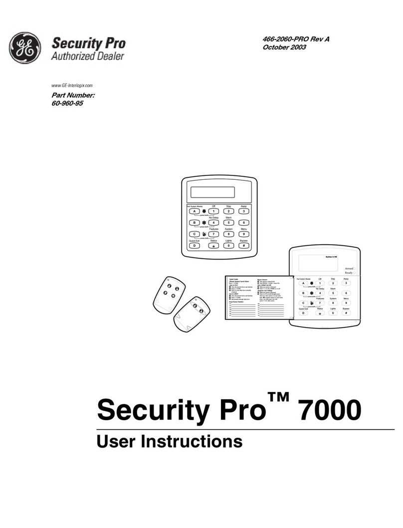
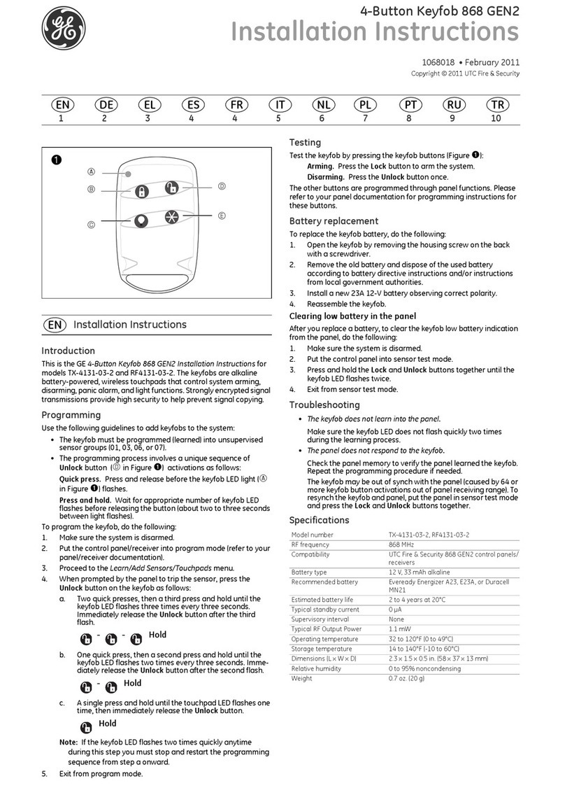
GE Euro Simon User manual

)
*(,QWHUORJL[
Part No:
60-911
ZZZ*(,QWHUORJL[6HFXULW\FRP
CODE
EMERGENCY
HOME CONTROL
HOME SECURITY
Bypass
System
Status
Doors &
Windows Motion
Sensors
Arm Disarm
9/05/63/4 7/81/2
On OffSensorMotion TimeDoors
Lights
Chime
AUX
Test Weekly
POLICEFIRE
Installation Instructions
466-1873-EUR Rev B
August 2002
Euro Simon
®
Security
System
ZZZ*(,QWHUORJL[6HFXULW\FRP

Declaration of Conformity
Manufacturer’s Name & Address: GE Interlogix, Inc.
2266 North Second Street
North St. Paul, MN, USA
55109
EU Representative:Interlogix Europe & Africa
Excelsiorlaan 28
B-1930 Zaventem
Belgium
Product Identification
Product: Simon 3 Security Panels
Model Numbers: 60-911-010-4-IE, 60-911-011-4-IE, 60-911-010-4-IT, 60-911-011-4-IT
Brand: GE Interlogix
R&TTE Directive
See EMC and LVD tests below
EMC Directive
TUV Product Services & GE Interlogix
Reports: CEQP 60-911 Simon 3 Euro Rev. C
EN 50130-4 (1995), EN 61000-3-2 (1995), EN 61000-3-3 (1995), EN 55022 (1998), EN 300220-3 (2000)
LVD Directive
GE Interlogix
Report: CEQP 60-911 Simon 3 Euro Rev. C
EN 60950: 1999-4 3rd edition
Means of Conformity
We declare under our sole responsibility that this product is in conformity with Directive 1999/5/EC (R&TTE); Directive 73/23/EEC (LVD); and Directive 89/
336/EEC (EMC) and based on test results using (non)-harmonized standards in accordance with the Directives mentioned.
Additional Tests: This equipment has been tested and found to comply with the following standards (which are no longer required for compliance).
Tested by
Interlogix
CTR21 (1998) +EG201 121 (1998)
TÜV
Report: TBR21/110501/01
TBR21
Network Compatibility Declaration
We declare under our sole responsibility that this product is designed to work with the networks in the countries marked with a check (
9
) and may have network-
ing problems with the countries that are not checked.
Due to the inherent differences in the individual PSTNs, certain software settings may need to be adjusted on a country to country basis. If it is desired to use this
equipment on a network other than the one on which it was originally installed, you should contact your equipment supplier.
Telecom Approval Notice
This equipment has been approved in accordance with the Council Decision 98/482/EC for pan-European, single terminal connection to the public switched tele-
phone network (PSTN). However, due to the differences between the individual PSTNs provided in different countries, the approval does not, of itself, give an
unconditional assurance of successful operation on every PSTN network termination point. In the event of problems, you should contact your equipment supplier
in the first instance.
Electrical Requirements
This device automatically adjusts to voltages within the range of 220 - 240 V 50 Hz.
Fuse: T 2A 250 VAC
Technical Service and Repair
If you experience trouble with this equipment, please contact your installer for service and repair information. Changes or modifications not expressly approved
can void the user’s authority to operate the equipment.
(
) Austria (
) Denmark (
) Germany (
9
) Ireland (
)Luxembourg (
) Poland (
)Sweden
(
) Belgium (
) Finland (
) Greece (
9
) Italy (
)Netherlands (
)Portugal (
)Switzerland
(
) France (
) Iceland (
) Liechtenstein (
)Norway (
)Spain (9)United Kingdom
6HFRQG6WUHHW1RUWK
1RUWK6DLQW3DXO01
3KRQH
86$&DQDGD
7HFKQLFDO6HUYLFH
)
*(,QWHUORJL[
*(,QWHUORJL[6LPRQ7RROER[DQG,QWHUURJDWRUDUHWUDGH
PDUNVRI*(,QWHUORJL[,QF$OORWKHUWUDGHPDUNVDUHSURSHUWLHVRI
WKHLUR QHUV

Euro
S
imon
S
ecurit
y
Sy
ste
m
Contents y
Contents
About This Manual ................................................................................................................1
Planning the Installation .........................................................................................................1
Panel Inputs/Outputs .......................................................................................................................... 1
Installing the System ..............................................................................................................1
System Components .......................................................................................................................... 1
Control Panel ................................................................................................................................. 2
System Devices .............................................................................................................................. 2
Planning Sensor Types & Locations ......................................................................................2
Device Locations ............................................................................................................................... 3
Control Panel ................................................................................................................................. 4
Remote Handheld Touchpad .......................................................................................................... 4
Keychain Touchpad ....................................................................................................................... 4
X-10 Modules .................................................................................................................................... 4
House Code and Unit Numbers ..................................................................................................... 4
Installing the System ..............................................................................................................5
Materials Needed ............................................................................................................................... 5
Opening the Panel Cover and Chassis ............................................................................................... 5
Mounting the Panel ............................................................................................................................ 6
Connecting Hardwire Devices ........................................................................................................... 7
AC Terminals ................................................................................................................................. 7
HWIN1, HWIN2, and DCOUT Terminals .................................................................................... 7
Wiring Interior Sirens ........................................................................................................................ 7
Hardwire Interior Siren .................................................................................................................. 7
Wiring Exterior Sirens ....................................................................................................................... 8
Hardwire Exterior Siren with Supervision ..................................................................................... 8
Hardwire Exterior Siren without Supervision ............................................................................... 8
Wiring Hardwire Contacts ................................................................................................................. 8
Wiring a Phone Line to the Panel ...................................................................................................... 9
Full Line Seizure ............................................................................................................................ 9
Connecting and Applying Power...................................................................................................11
AC Power Connections .................................................................................................................11
Installing X-10 Modules .................................................................................................................. 12
Lamp and Appliance Modules .....................................................................................................12
Universal Module ........................................................................................................................ 12
Sensor Installation ............................................................................................................................ 13
Programming ........................................................................................................................13
Entering Program Mode ................................................................................................................... 13
Exiting Program Mode ..................................................................................................................... 13
Reset Memory to the Factory Defaults ............................................................................................ 13
Set the Clock .................................................................................................................................... 13
Adding (Learning) Sensors .............................................................................................................. 14
Deleting Sensors .......................................................................................................................... 15
X-10 Module Operation ................................................................................................................... 15
Numbered Options ........................................................................................................................... 16
Option 01: Panel Piezo Beeps ...................................................................................................... 17
Option 02: Panel Voice ................................................................................................................ 17
Option 03: Latchkey .................................................................................................................... 17
Option 04: Primary Phone Number ............................................................................................. 18
Option 05: Secondary Phone Number ......................................................................................... 18
Option 06: Downloader Phone Number ...................................................................................... 18

Euro Simon Security System
Contents y
Option 07: Account Number ........................................................................................................ 18
Option 08: Phone Lock ................................................................................................................ 18
Option 09: Downloader Code ...................................................................................................... 19
Option 10: Entry Delay ................................................................................................................ 19
Option 11: Exit Delay .................................................................................................................. 19
Option 12: Phone Mod 1 .............................................................................................................. 19
Option 13: Phone Mod 2 .............................................................................................................. 20
Option 14: DTMF Dialing ........................................................................................................... 20
Option 15: No Activity Timeout .................................................................................................. 20
Option 16: Auto Phone Test ......................................................................................................... 21
Option 17: Dialer Delay ............................................................................................................... 21
Option 18: Alarm Cancel Report .................................................................................................21
Option 19: RF Timeout ................................................................................................................ 21
Option 20: Manual Phone Test .................................................................................................... 21
Option 21: Opening Reports ........................................................................................................ 22
Option 22: Closing Reports ......................................................................................................... 22
Option 23: Force Armed Report ..................................................................................................22
Option 24: AC Power Failure Report .......................................................................................... 22
Option 25: CPU Low Battery Report .......................................................................................... 22
Option 26: Fail to Communicate .................................................................................................23
Option 27: Ring/Hang/Ring ......................................................................................................... 23
Option 28: No Delay from Keychain Touchpad .......................................................................... 23
Option 29: Panel Piezo Alarms .................................................................................................... 24
Option 30: Panel Panic Alarms .................................................................................................... 24
Option 31: Downloader Enable ...................................................................................................24
Option 32: 300 Baud .................................................................................................................... 24
Option 33: Audio Verification ..................................................................................................... 24
Option 34: Fail to Open Report ................................................................................................... 25
Option 35: Fail to Close Report ................................................................................................... 25
Option 36: Sensor Activated Light Lockout Start Time .............................................................. 25
Option 37: Sensor Activated Light Lockout Stop Time .............................................................. 25
Option 38: Auto Arm ................................................................................................................... 25
Option 39: Siren Timeout ............................................................................................................ 26
Option 40: Trouble Beeps ............................................................................................................ 26
Option 41: Chime Voice .............................................................................................................. 26
Option 42: Speaker Level ............................................................................................................ 27
Option 43: Voice Event Notification Phone Number .................................................................. 27
Option 44: Voice Event Notification Phone Mod 3 ..................................................................... 27
Option 45: Sensor Alarm Restoral Report ................................................................................... 27
Option 46: Fire Shutdown - 2-Way .............................................................................................. 28
Option 47: 2-Way Mode .............................................................................................................. 28
Option 48: Panic Talk - 2-Way .................................................................................................... 28
Option 49: Arming LEDs Shutdown ........................................................................................... 28
Option 50: RF Jam Detect ........................................................................................................... 28
Option 51: 24 Hour Sensor Tamper ............................................................................................. 29
Option 52: Unvacated Premises ................................................................................................... 29
Option 53: Hardwire Siren Supervision ....................................................................................... 29
Option 54: Access Code Length ..................................................................................................29
Option 55: Status Beep Volume ................................................................................................... 30
Option 56: Call Waiting ............................................................................................................... 30
Option 57: Supervisory/Tamper Report ....................................................................................... 30
Option 58: Remote Touchpad Arming ......................................................................................... 31
Option 59: Exit Extension ............................................................................................................ 31
Option 60: Secure Arming ........................................................................................................... 31
Option 61: Demo Mode ............................................................................................................... 31
Option 62: Reserved .................................................................................................................... 31
Option 63: 24 Hour Time ............................................................................................................. 31

Euro Simon Security System
Contents y
Option 64: No Arm on Panel Low Battery .................................................................................. 32
Option 65: No Usage Report ....................................................................................................... 32
Option 66: External Siren Delay .................................................................................................. 32
Option 67: Quick Exit .................................................................................................................. 32
Option 68: Swinger Shutdown ..................................................................................................... 32
Option 69: SIA Limits ................................................................................................................. 33
Option 70: Line Cut Detection ..................................................................................................... 33
Option 71: Programming Report ................................................................................................. 33
Option 72: Supervisory Time ....................................................................................................... 33
Option 73: Modem Sensitivity ..................................................................................................... 34
Option 74: Silent Panel Police Panic ...........................................................................................34
Option 75: VOX Mic Gain .......................................................................................................... 34
Option 76: VOX Gain Range ....................................................................................................... 34
Option 77: Manual Mic Gain ....................................................................................................... 34
Option 78: VOX Receiver Gain ...................................................................................................35
Option 79: Panel Cover Tamper ..................................................................................................35
Option 80: Alarm Report Verification.......................................................................................... 35
Programming System Access Codes ............................................................................................... 35
Testing the System ...............................................................................................................36
Control Panel ................................................................................................................................... 36
Sensor Testing................................................................................................................................... 37
Improving Sensor/Panel Communication ........................................................................................ 38
Antenna ........................................................................................................................................ 38
If a Sensor Fails the Sensor Test .................................................................................................. 38
Phone Communication ................................................................................................................. 39
Off-Site Phone Operation ............................................................................................................ 39
Central Station Communication ................................................................................................... 39
2-Way Voice Operation ................................................................................................................ 40
Voice Event Notification .............................................................................................................. 40
X-10 Operation ............................................................................................................................ 41
Manual Lamp Module Control .................................................................................................... 41
X-10 Siren and Lamp Module Functions .................................................................................... 41
Appendix A: Troubleshooting .............................................................................................42
System Status ............................................................................................................................... 42
Control Panel ............................................................................................................................... 42
Options (Programmable by the homeowner) ............................................................................... 42
Sensors ......................................................................................................................................... 42
X-10 Modules .............................................................................................................................. 43
Appendix B: System Configuration .....................................................................................43
Sensor Assignments/Locations ........................................................................................................ 43
Alphabetical Listing of Sensor Names ............................................................................................ 44
Sensor Group Characteristics ........................................................................................................... 44
Home Control Planning ................................................................................................................... 46
System Access Codes ...................................................................................................................... 46
Option Settings ................................................................................................................................ 46
Specifications .......................................................................................................................49
Quick Reference Table.............................................................................................Back Page

Euro Simon Security System1
About This
Manual This manual provides information for planning, installing, programming, and testing this secu-
rity system. When necessary, this manual refers you to other documentation included with
compatible devices.
Planning sheets are included for you to record sensor locations and software programming set-
tings.
Planning the
Installation This section describes system capabilities to help you get familiar with the system. “Appendix
B” provides planning sheets with tables that let you record the hardware and programming
configuration of the system. Fill in all necessary information ahead of time to help prepare for
system installation.
Panel Inputs/Outputs
The following describes the panel hardware input/output capabilities.
•Power: Input for AC power.
•2 Siren Outputs/Zone Inputs: Terminals for connecting hardwire sirens or normally
closed (NC) loop switch circuits. These terminals cannot provide both functions simulta-
neously.
•Phone Line Connection: Lets users access and control their system from a remote phone
and allows the panel to communicate with central monitoring station.
Installing the
System This section describes how to install the system control panel. Before starting the installation,
plan your system layout and programming using the worksheets provided in “Appendix B.”
Installing the system consists of the following:
• Determining Panel and Device Locations
• Mounting the Panel
• Connecting Sirens
• Connecting Normally Closed Loop Switch Circuits
• Connecting the Phone Line to the Panel
• Connecting and Applying Power
System Components
The security system has three types of components: the control panel, devices that report to the
panel, and devices that respond to commands from the panel (see Figure 1).

Euro Simon Security System 2
Figure 1. Typical Security System Components
Control Panel
The control panel is the main processing unit for all system functions. It receives and responds to
signals from wireless sensors and wireless touchpads throughout the premises. For monitored
systems, the panel can be connected to the premises phone line for central monitoring station
reporting.
Two panel models are available. One has an on-board 2-way voice microphone, the other does
not. The Interrogator®200 Audio Verification Module can be added to either panel.
User Interface
When the panel cover is closed, the panel buttons operate the security system. The user operates
the panel by pressing panel buttons or by using a touchpad. See the User Manual for complete
operation instructions.
When the panel cover is open, the buttons program the security system. The panel can be pro-
grammed on-site by the installer or user, or from off-site using ToolBox®software. See the “Pro-
gramming” section of this manual for complete on-site programming instructions.See the
ToolBox manual and ToolBox on-line help for off-site programming instructions.
Panel Tamper
If the panel cover is opened while the system is armed, an intrusion alarm occurs. When the sys-
tem status button is subsequently pressed, the panel voice announces System Access Alarm.
System Devices
The system can monitor up to 24 sensors and may use any of the following:
Door/Window Sensor
For intrusion protection, install Door/Window sensors on all ground-floor doors and windows. At
a minimum, install them in the following locations:
• All easily accessible exterior doors and windows.
• Interior doors leading into the garage.
• Doors to areas containing valuables such as cabinets and closets.
X - 1 0 P O W E R H O U S E
1
3
5
9
1 3
7
1 1
1 5
A
C
E
I
M
GK
O
U N IT C O D E H O U S E C O D E
C O N T IN U O U S
M O M E N T A R Y
S O U N D E R O N L Y
S O U N D E R & R E L A Y
R E L A Y O N L Y
O N O F F
1
3
5
9
1 3
7
1 1
1 5
A
C
E
I
M
GK
O
1
3
5
9
1 3
7
1 1
1 5
A
C
E
I
M
GK
O
7
4
1
8 9
5
2
6
3
O f f
sP
E M E R G E N C Y
O
d&sr e s H o l hB to eK y
D I S A R M
S Y S T E M
S T A T U S
D o o r s &
W i d o w s
A R M
A R M
S e s o r s
M o t i o
-
H O M E S E C U R I T Y
C O D E
H O M E C O N T R O L
E M E R G E N C Y
S t a t u s
S y s t e m
9 / 0
S e s o r s
M o t i o
5 / 6
D i s a r m
7 / 8
W i d o w s
D o o r s &
1 / 2
A r m
3 / 4
O f fO
A U X
S e s o rT i m e
P O L I C E
L i g h t s
T e s t W e e k l y
S p e c i a l
M o t i o
D o o r s
F I R E
C h i m e
Motion Sensor
X-10 Modules
Smoke
Sensor
Keychain
Touchpad
Door/Window
Sensor
Touchpad
Remote
Handheld

Euro Simon Security System3
Motion Sensor
Motion sensors are ideal whenever it is not practical to install door/window sensors on every
opening. Identify areas where an intruder is likely to walk through. Large areas in an open
floor plan, downstairs family rooms, and hallways are typical locations for indoor motion sen-
sors. For installations with pets, use pet immune motion sensors.
Smoke Sensor
Smoke sensors provide fire protection by causing an alarm to sound throughout the house. You
can add smoke sensors near sleeping areas and on every floor of the house. Avoid areas that
could have some smoke or exhaust such as attics, kitchens, above fireplaces, dusty locations,
garages, and areas with temperature extremes. In these areas you may want to install Rate-of-
Rise sensors to detect extreme temperature changes. See the instructions packaged with the
smoke sensor for complete placement information.
Keychain Touchpad
The Keychain Touchpad lets you turn the system on and off from right outside the home or
activate a panic alarm if there is an emergency. If you have X-10 Lamp Modules, you can use
keychain touchpads to turn all system controlled lights on and off.
Remote Handheld Touchpad
The Remote Handheld Touchpad lets you turn the system on and off while in the home, turn
system controlled lights on and off (all or individual lights), or activate a panic alarm if there is
a non-medical emergency.
X-10 Modules
Some panel models work with any of the following modules:
•X-10LampModule
• X-10 Appliance Module
• X-10 Powerhorn/Remote Siren Module
• X-10 Universal Module
Planning
Sensor Types &
Locations
The first step to an easy and successful installation is to decide what areas or items to protect,
which lights or appliances to operate, and the best location for the panel, touchpad, sensors,
and sirens.
Metal objects, mirrors, and metallic wallpaper can block signals sent by the wireless sensors.
Make sure there are no metal objects in the way when installing the system.
Use the planning tables in “Appendix B” to determine the appropriate Sensor Group for the
sensors you will be adding. You’ll need to understand the application for each sensor. For
example, Keychain Touchpads are typically programmed as sensor group 01 (Portable panic),
used to send an intrusion alarm to a central monitoring station. This sensor type is instant intru-
sion, it does not require restoral or supervisory communication with the panel and it is active in
4 arming levels (disarm, arm doors & windows, arm motion sensors and arm doors/windows
and motion sensors).
Recommended Sensor Groups
Device Recommended Sensor Group
Keychain Touchpad 01, 03, 06, 07
Remote Handheld 01, 03, 06, 07
Motion Sensor 17 (intrusion), 25 (chime)
Smoke Sensor 26
Exterior Door 10
Interior Door 14
Windows Sensor 13

Euro Simon Security System 4
Device Locations
Control Panel
Locate the panel where alarm sounds can be heard and is easily accessible for operation.
Do not install the panel near a window or door where it can be reached easily by an intruder.
Remote Handheld Touchpad
Locate Remote Handheld Touchpads where they will be convenient and offer quick access to the
user.
Keychain Touchpad
Keychain Touchpads attach to the owner’s key ring or can be conveniently carried.
X-10 Modules
The system can control up to 8 individual unit numbers on Lamp, Appliance, and Universal Modules.
House Code and Unit Numbers
Note
All Lamp Modules with the
same house code will turn
on or flash as a group during
an alarm or when operating
the “Light” button on a Key-
chain Touchpad.
Each device (lamp, appliance, etc.) controlled by the panel must have an identification setting.
The modules use two dials to set identification codes: one with letters A through P and one with
numbers 1 through 16.
The lettered dial sets the house code, which enables the system to differentiate this home from
other homes in the area. Set all modules (except the remote siren) and the panel to the same
house code.
Note
When unit numbers 9-16 are used for lamp modules, they can only be controlled by an all on or all off
command. A lamp will flash to the arming level if its unit number is set to 10. A lamp set to unit number
10 will flash once if the panel is disarmed, twice if doors & windows are armed, etc. The remote siren
can be set to any unit number to hear alarm sounds. Set it to unit number 9 to also hear arming level
beeps, status beeps, and trouble beeps. Do not use a lamp module to control appliances. Use an appli-
ance module, since the wattage rating on Lamp Modules is less than on Appliance Modules.
The numbered dial sets the unit number, which identifies and lets you control a specific device.
Each device must have a unique unit number (1-8) to be individually controlled. For example,
lights and appliances operated from a Remote Handheld Touchpad or operated by a sensor; or
lights programmed to go on during the entry/exit delay or at scheduled times.
¾To Fill Out the Home Control Planning Table:
1. Set the house code on all modules (except the remote siren) to the same letter.
Note
The house code instructions
that come with the Power-
horn Siren won’t work with
this panel. Follow the house-
code instructions given here.
2. Set the Remote Siren house code to the next alphabetical letter. For example, if you chose
house code B in step 1 above, set the remote siren house code to C.
3. Set the module unit numbers.
Note
If you are using a Universal
Module to operate a device,
make sure to assign a
unique unit number to this
module, choosing from 1-8.
4. List the location of the lamp or appliance in the Location column of the Home Control Plan-
ning Table.
5. Write the location of each module on an adhesive note and label the module.
6. Decide if the device should be activated by sensors, entry/exit delay, time, or a combination.
An example of sensor activation is using a motion sensor to turn on a light. Record the infor-
mation in the appropriate columns.
Use the following tables to help plan X-10 module installation.
House Code Assignments
House Codes Results
A through P Set all modules to the same house code except the remote
sirens.
Next Higher House Code Remote Siren must be set to the next higher alphabetical letter.

Euro Simon Security System5
Installing the
System This section describes how to open the panel for mounting, mount the panel, connect sirens,
hardwire contacts, and the AC power transformer.
Materials Needed
• Pencil
• Phillips Screwdriver
• Small Standard Screwdriver
Opening the Panel Cover and Chassis
Tabs at the top of the panel secure and release the front cover and the chassis. The plastic
hinges on the panel bottom allow the cover and chassis to swing down and out of the way (see
Figure 2)
Unit # Result
1 - 8 Used for sensor-activated, time-activated, and entry/exit delay lights.
• Sensor-activated lights are enabled and disabled by pressing the Lights
Sensor button on the panel.
• Time-activated lights are enabled and disabled by pressing the Lights
Time button on the panel.
If using the universal module to operate a device, be sure to assign a unique
unit number.
• The STAR button on the Keychain Touchpad activates the universal mod-
ule controlled device or turns on special lights if programmed.
9Used for remote siren or light control.
• For remote siren use, House Code must be set to next higher number to
hear arming level beeps, status beeps, and trouble beeps.
• For light control, lamp modules with this setting are controlled by an all
on or all off command.
10 Used for remote siren or light control.
• For remote siren use, House Code must be set to next higher number and
only alarm sounds occur at this setting.
• For light control, lamps will flash according to selected arming level and
are controlled by an all on or all off command.
11 - 16 Used for lamp modules and controlled by an all on or all off command.

Euro Simon Security System 6
Figure 2. Opening the Panel Cover and Chassis
Mounting the Panel
Mount the panel on a wall as follows:
1. Choose a panel location and run all necessary power, phone, siren, and hardwire contact
wires to the location.
2. Hold the panel against the wall and mark the mounting hole locations with a pencil (see Fig-
ure 3).
Figure 3. Mounting Hole/Wire Access Locations
T e s t W e e k l y
C O D E
S t a t u s
S y s t e m
9 / 0
W i d o w s
D o o r s &
S e s o r s
M o t i o
D i s a r m
5 / 6
A r m
3 / 4 7 / 8
O O f f
A U X
S e s o r
M o t i o T i m e
F I R E P O L I C E
L i g h t s
S p e c i a l
H O M E C O N T R O L
E M E R G E N C Y
H O M E S E C U R I T Y
D o o r s
C h i m e
1 / 2
Press tab with thumb,
then swing cover down. screwdriver, then
down.
swing chassis
Press tab up with
- - - - -
- - - -
H W I N 2 H W I N 1D C O U T
A C A C
Mounting
Holes
Wire
Access
Wire
Access

Euro Simon Security System7
3. Insert anchors into holes where studs are not present.
4. Feed all wires through wire access areas (see Figure 3).
5. Install all screws and tighten gently.
Connecting Hardwire Devices
The panel has 5 screw terminals located on the upper-right corner of the circuit board (see Fig-
ure 3) for connecting AC power, sirens and/or hardwire detectors.
AC Terminals
A fused terminal block is used for connecting the panel to a mains supply. The terminal block
is pre-wired from the factory to a built-in step-down transformer.
HWIN1, HWIN2, and DCOUT Terminals
Note
These terminals cannot pro-
vide both functions simulta-
neously.
These terminals are dual purpose and can be used for either siren or hardwire detector connections.
Sirens
From the factory, these terminals are set up for siren operation with HWIN1 handling interior
sirens (status and alarm sounds), HWIN2 handling exterior sirens (alarm sounds only), and
DCOUT providing the positive (+) voltage.
Note
The total current available
from the DCOUT terminal is
250 mA at up to 50° C.
With Option 53: Hardwire Siren Supervision turned on, sirens connected to HWIN1 and
HWIN2 are supervised and require a 4.7k resistor in the circuit. If either of these terminals is
not used with Option 53 on, you must connect a 47k resistor between the unused terminal and
DCOUT.
Hardwire Detectors
To set up HWIN1 and/or HWIN2 for hardwire detectors, make the required connections as
described under “Wiring Hardwire Detectors,” then proceed to the “Programming” section to
add (learn) them into panel memory.
Wiring Interior Sirens
Panel terminal HWIN1 can be used for connecting interior sirens and activates for status and
alarm sounds.
Interior sirens must always be wired with a resistor in the circuit. For circuit supervision which
allows the panel to detect if the siren wire is cut (open), Option 53: Hardwire Siren Supervision
must be turned on (see the “Programming” section).
Hardwire Interior Siren
Note
Do not install the resistor at
the panel terminals. This
does not provide supervision
of the wire. If you are only
installing an interior siren
and Option 53 is on, you
must connect a 47k resistor
between the HWIN2 and
DCOUT terminals.
Connect a hardwire interior siren to the panel using a 4.7k resistor as shown in Figure 4. The
resistor must be connected across the siren wires as close to the siren as possible.
Figure 4. Hardwire Interior Siren with Supervision
H W I N 2 H W I N 1D C O U T
A C A C
SIREN
4.7k Resistor
(Locate at siren)

Euro Simon Security System 8
Wiring Exterior Sirens
Panel terminal HWIN2 can be used for connecting exterior sirens and activates when intrusion
and fire alarms occur.
Exterior sirens can be wired with or without a resistor in the circuit for supervision. For circuit
supervision which allows the panel to detect if the siren wire is cut (open), Option 53: Hardwire
Siren Supervision must be turned on (see the “Programming” section).
Hardwire Exterior Siren with Supervision
Note Do not install the
resistor at the panel termi-
nals. This does not provide
supervision of the wire. If
you are only installing an
interior siren and Option 53
is on, you must connect a
47k resistor between the
HWIN2 and DCOUT termi-
nals.
Connect a hardwire exterior siren to the panel using a 4.7k resistor as shown in Figure 5. The
resistor must be connected across the siren wires as close to the siren as possible.
Figure 5. Hardwire Exterior Siren with Supervision
Hardwire Exterior Siren without Supervision
With Option 53 turned off, connect a hardwire exterior siren to the panel without a resistor as
shown in Figure 6.
Figure 6. Hardwire Exterior Siren without Supervision
Wiring Hardwire Contacts
You can connect hardwire reed switches (normally closed loop only) to HWIN1 and/or HWIN2,
if either terminal is not being utilized for a hardwire siren.
H W I N 2 H W I N 1D C O U T
A C A C
SIREN
4.7k Resistor
(Locate at siren)
H W I N 2 H W I N 1D C O U T
A C A C
SIREN
Connect only normally closed (N/C) reed switches to HWIN1 and/or HWIN2. Other
Do not put the panel antenna in the wall for installations that require ante
!
types of hardwire detectors should not be used.
Caution
!

Euro Simon Security System9
Note
Do not install the resistor at
the panel terminals. This
does not provide supervision
of the wire
The total resistance of the wire loop must not exceed 3 ohms. This allows you to use up to 61 meters
of 2-conductor, .64 mm diameter stranded wire.
Connect hardwire reed switches to the panel using a 47k resistor as shown in Figure 7. The resistor
must be connected at the last switch in the circuit.
Figure 7. Connecting Normally Closed Hardwire Reed Switches
Wiring a Phone Line to the Panel
You can connect a phone line to the panel for systems monitored by a central monitoring sta-
tion and/or systems that notify users by voice event notification.
Basically, there are two methods for connecting the panel to a phone line; full line seizure and
no line seizure.
Full Line Seizure
This method requires that the panel be wired ahead (or in front) of all other phones, answering
machines, computers, or any other devices on the phone line. This allows the panel to take over
(seize) the phone line, even if another device on the line is in use.
An RJ-31X (CA-38A) jack should be installed when wiring for full line seizure. This lets the
user quickly and easily disconnect the panel from the phone line in case the panel disables the
phone line due to a malfunction.
¾Full Line Seizure Wiring with an RJ-31X
1. Run a 4-conductor cable from the TELCO block to the RJ-31X (A in Figure 8).
2. Connect the 4-conductor cable wires to the RJ-31X (B in Figure 8).
3. Disconnect the TIP (+) and RING (-) premises phone jack wires from the TELCO block
and splice them to the 4-conductor cable Black and White (or Yellow) wires (C in Figure
8). Use weatherproof wire connectors for these splices.
4. Connect the 4-conductor cable Green wire to the TELCO block TIP (+) post and connect
the Red wire to the TELCO block RING (-) post (D in Figure 8).
5. Connect the phone cord included with the panel to the RJ-31X and the panel LINE IN jack
(E in Figure 8)
H W I N 2 H W I N 1D C O U T
A C A C
47k Resistor

Euro Simon Security System 10
Figure 8. Full Line Seizure Wiring with RJ-31X
¾Full Line Seizure Wiring without RJ-31X
1. Connect the green, red, brown, and gray wires of the 8-conductor phone cord included with
the panel as shown in Figure 9. Use weatherproof wire connectors for all splices.
2. Connect the plug end of the phone cord to the panel LINE IN jack
¾Full Line Seizure Wiring with 1 Premises Phone
If a single phone is all that exists on the premises, full line seizure can be accomplished without
an RJ-31X.
Note
If the customer ever adds a
phone or other phone device
to another phone jack, full
line seizure no longer exists.
Inform the customer to con-
tact you if they want to add a
phone or other device so
that you can rewire for full
line seizure by adding an
RJ-31X.
1. Disconnect the phone from the premises phone jack and plug it into the panel PHONE jack
(A in Figure 10). This jack is disconnected automatically whenever the panel reports.
Connect the phone cord included with the panel to the panel LINE IN jack and the premises
phone jack (B in Figure 10)
- - - - -
- - - -
H W I N 2 H W I N 1D C O U TA C A C
E
BRN GRY
GRN RED
Black
Green
Red
White
(or Yellow)
B
A
D
C
TIP
(+) (-)
RING
Red
Green
Black
Green
White (or Yellow)
Red Premises
Phone Jack
Wires
- - - - -
- - - -
H W I N 2 H W I N 1D C O U TA C A C
Brown
(T1) (R1)
Gray
Green
(Tip) Red
(Ring)
Figure 9. Full Line Seizure Wiring without RJ-31X

Euro Simon Security System11
Figure 10. Full Line Seizure Wiring with 1 Premises Phone
Connecting and Applying Power
This section describes how to connect and apply AC and backup battery power to the panel.
AC Power Connections
The panel must be wired to an AC mains supply with a voltage range of 220-240 VAC, 50 Hz.
The panel voltage range appears on a label inside the panel (see Figure 11).
Electrical codes vary depending on the country and city where the system is installed. It is the
installer’s responsibility to ensure that the electrical installation is safe and conforms to all
applicable codes, laws, and regulations. Only qualified persons should connect the panel to the
mains supply and insert the 2 amp fuse. Read all instructions and safety warnings prior to mak-
ing any connections.
Note
The panel does not have a
power switch. A readily
accessiblepowerdisconnect
device must be incorpo-
rated in the building installa-
tion wiring to comply with
safety standards.
A fused spur or other disconnect device must be installed in the building mains wiring in a
location near the panel. Wire having a cross sectional area of at least 0.75 mm2must be used
for connecting to the disconnect device. However, if the wire length between the disconnect
device and the building mains is less than 2 m, wire having a cross sectional area of 0.5 mm2
can be used.
Once the panel has been connected to the mains supply, always isolate the supply before open-
ing the panel cover. After opening the panel cover, ensure the mains supply has been isolated
by checking the voltage on the mains terminal block inside the panel with a multimeter or neon
voltage tester. If the hot and neutral conductors are reversed in the building wiring, the wiring
inside the panel would still be live when the disconnect device was open.
Powering Up the Panel
Note
To avoid Low Battery mes-
sages, connect the backup
battery before enabling AC
power to the panel.
1. Turn off/disable the appropriate AC circuit at the mains supply.
2. Connect AC power wiring to the panel as described above and as shown in Figure 11 (A).
3. Install and connect the backup battery (B in Figure 11).
4. Turn on/enable the appropriate AC circuit at the mains supply.
- - - - -
- - - -
H W I N 2 H W I N 1D C O U TA C A C
Install/replace only with a Portalac PE6V3.2 rechargable, lead-acid battery. Observe
polarity when making battery connections. Reversing the polarity may cause damage
to the panel. There is a risk of explosion if the wrong battery type is connected.
Warning
!

Euro Simon Security System 12
Figure 11. Connecting and Applying Power
Installing X-10 Modules
¾Lamp and Appliance Modules
1. Set the unit code dial to a unit number different from all other X-10 modules (between 1 and
8).
2. Set the house code for the installation.
3. Plug the module into a wall outlet.
4. Plug the lamp/appliance into the module.
Universal Module
1. Set the unit code dial to a unit number different from all other X-10 modules (between 1 and
8).
2. Set the house code for the installation.
3. Set the module switches to momentary and relay only.
+
-
- - - - -
- - - -
H W I N 2 H W I N 1D C O U T
A C A C
Black
B
Red
A
Voltage
Label Here
Requirements
Blue
BRN
L
N
Do not put the panel antenna in the wall for installations that require ant
e
for external antennas
!
Do not use Lamp Modules on appliances or lamps with 300-watt or larger bulbs
Caution
!

Euro Simon Security System13
4. Connect the module terminals to the desired device terminals.
5. Plug the universal module into a wall outlet.
Note
See “Light and Appliance
Controls” to program a Key-
chain Touchpad to activate a
Universal Module controlled
device.
Sensor Installation
Program sensors and devices before you install them. Use the following section to program the
panel and add the sensors to panel memory.
Programming Entering Program Mode
There are 2 codes you can use to enter program mode.
Utility Access Code 1 (Dealer Code)
Depending upon how Option 54 is set, the default utility access code is 654321, 54321, 4321
(factory default), or 321. This code can be used for all programming.
Utility Access Code 2 (Installer Code)
Depending upon how Option 54 is set, the default access code is 654321, 54321, 4321 (factory
default), or 321. This code is limited to changing all but the following: Utility Access Code 1,
Options 4, 5, 6, 8, 9, 12, 13, 54, and 69.
1. Open the panel cover.
2. Enter Utility Access Code 1 or 2 using the numbered keys.
The panel is now in program mode. Follow the programming arrows on the panel label. The
system prompts you through programming steps with beeps and voice messages.
Note
Do not remove panel power
while in program mode. Pro-
gramming changes are
saved only when exiting pro-
gram mode (closing the
panel cover).
¾Program the panel in this order:
1. Set the panel clock.
2. Add (learn) sensors.
3. Set House Code and Light & Appliance Controls (Entry/Exit activated lights, Sensor acti-
vated lights, Time activated lights).
4. Change numbered Options as needed.
Exiting Program Mode
Close the cover to exit program mode when you are finished programming.
Reset Memory to the Factory Defaults
Note
If Option 8: Phone Lock is
on, options 04, 05, 06, 08,
09, 12, 13, 54 and Dealer
Code will not reset to their
defaults.
1. Open the panel cover and enter Utility Access code 1.
2. Unplug the transformer and disconnect the battery.
3. Simultaneously press and hold Cancel, Clock Set, and
Minutes +.
4. Restore power to the panel with either the battery or the transformer while pressing these
three buttons. The panel announces “Hello. System XX OK.” Release the buttons.
5. Connect the remaining power source to the panel.
Set the Clock
1. Press Clock Set from the Start Menu.
2. Press the Hours + and – keys and listen to the voice prompts. Stop when panel voice
announces the correct hour.
3. Press the Minutes + and – keys and listen to the voice prompts. Stop when the panel
announces the correct minutes.
4. Press Done. The panel announces the set time.
Do not power down the panel while in program mode or all programming will be lost.
The panel stores programmed information only when you exit program mode (close
the cover and leave closed for at least 5 seconds.
Caution
!

Euro Simon Security System 14
Adding (Learning) Sensors
These instructions describe how to add sensors, touchpads and other system devices into panel
memory. The panel recognizes a sensor when you press a sensor program button, press and
release a tamper switch, press a sensor test button, or put a sensor into alarm.
Note
The hardwire inputs must have sirens or hardwire sensors with 47k Ohm resistors connected between
the DCOUT and HWIN1 or HWIN2 terminals before learning in a sensor. If one of these connections is
not made, the panel will learn in a hardwire zone.
Note
If you are installing a sensor on a gun case, jewelry box, or similar usage, and the sensor is active in
level one, you must sub-disarm to avoid putting the panel into alarm when the sensor and the magnet
are separated.
The following table, “Device Programming,” describes the programming button location for
each device
When adding (learning) sensors, the panel uses an ascending numbering sequence starting with
1. You can override this by entering the desired sensor number using the numbered keys.
Use the Table in Appendix B, which was filled out during the system plan
Device Programming
Device To Program
Door/Window Sensor Press button on top of sensor (cover removed) or trip tamper
Motion Sensor Press button on back of sensor (mounting plate removed) or
trip tamper
Smoke Sensor Trip tamper, press test button, remove from base or put sen-
sor in alarm
Keychain Touchpad Press and hold Lock & Unlock buttons together
Remote Handheld Touchpad Press the EMERGENCY buttons
Hardwire Sensors Separate sensor from magnet
Freeze & Water Trip tamper or press and hold button on top of the sensor
(cover removed) until control panel confirms program-
ming. If button is not held down long enough, SYSTEM
STATUS reports sensor as open.

Euro Simon Security System15
¾To add a hardwire or RF sensor or remote control:
1. Press Add. The panel announces “Select from Main Menu.”
2. Press Sensor/Remote. The panel announces “Press button on sensor.”
3. Press the sensor program button or release sensor tamper switch. The panel announces
“Keychain Remote. Press sensor again for next name or press Done to select.”
4. Press Sensor/Remote repeatedly until you hear the name or item you want to use. An
alphabetical list of names the panel uses appears in Appendix B. Each name may be used
more than once.
Note
For a more specific location
name, press Option # for
compass directions (north,
northeast, east, southeast,
south, southwest, west,
northwest).
5. Press DONE when you hear the desired name. The panel announces “Use numbered keys
to enter sensor group.”
6. Enter the 2-digit sensor group. The panel announces the first available sensor number and
sensor group, then prompts you to press DONE to accept.
Note
If you wish to use a sensor
number other than the next
one available, use the num-
bered keys to enter a 2 digit
sensor number immediately
after entering the sensor
type.
7. Press DONE. The panel confirms programming by announcing the sensor number, name,
and group.
¾To delete sensors:
1. Press Delete. The panel announces “Select from Main Menu.”
2. Press Sensor/Remote repeatedly until you hear the name and number you want deleted,
then press DONE. The panel announces that the sensor is deleted.
X-10 Module Operation
Use the following procedure to program X-10 module operations into panel memory. Notice
that the Light Control button is used to program all X-10 module operations (light, appliance,
and universal).
¾To program the house code:
1. Press Add.
2. Press Light Control repeatedly until you hear the desired house code letter.
3. Press DONE.
4. Set the HOUSE dial on each lamp, appliance, and universal module, to the same letter.
5. Set the HOUSE dial on powerhorn/remote sirens to the next sequential alphabetical letter.
¾To add an entry/exit activated module:
1. Press ADD.
2. Press Light Control.
32
978
10
645
Test System should be checked
422-2806 Rev A
Set
Code
Access Clock
+
Delete
Delete
press
-
+
Hours
at least every three years.
To delete an option or access code
Hold key or press
and follow the voice
repeatedly until you
hear the desired item.
Note:
Cancel
and
Test
Cancel
DONE
Minutes
, then
DONE
See Note
If you make a mistake or want to
Sensor or Phone Test
follow the voice prompting.
To select a test, press
start over press
prompting.
by a qualified technician
Delete
START MENU
Add
Version 3
MAIN MENU
*
Remote
Sensor/
**
Control
Light Option #
**
Sensors
-
*
Entry/Exit
Delay
CONTROL MENU
*Press for program
information.
Instruction
Add Option
Summary
Unit #
Add
Press
Clock Set
Press
Set Clock
DONE
Chime Voice
Latchkey Time
Panel Voice
Add Option #
Press
Option #42:
Option #43:
Option #55:
Option #41:
Option #2:
Option #3:
Option #36:
Option #37:
See Note
Sensor Activated Light Lockout Start Time
Sensor Activated Light Lockout Stop Time
and follow voice prompts.
Pager Phone Number
Speaker Volume
Status Beep Volume
Option #1:
Panel Beeps
use red numbers to enter 4-digit code.
Add Access Code
Hours
Access Code
See Note
Minutes
Time
Cancel
Table of contents
Other GE Security System manuals

GE
GE SmartHome Series User manual

GE
GE Interlogix 60-875 Simon User manual

GE
GE Simon Security System User manual

GE
GE JSC1300 User manual

GE
GE SIMON XT User manual

GE
GE Deluxe 45117 User manual

GE
GE INT-22.5R1-24 User manual

GE
GE AL-1291 Point ID User manual

GE
GE TX-7201-05-1 User manual

GE
GE AS610RF User manual