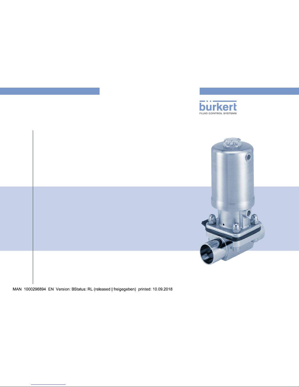
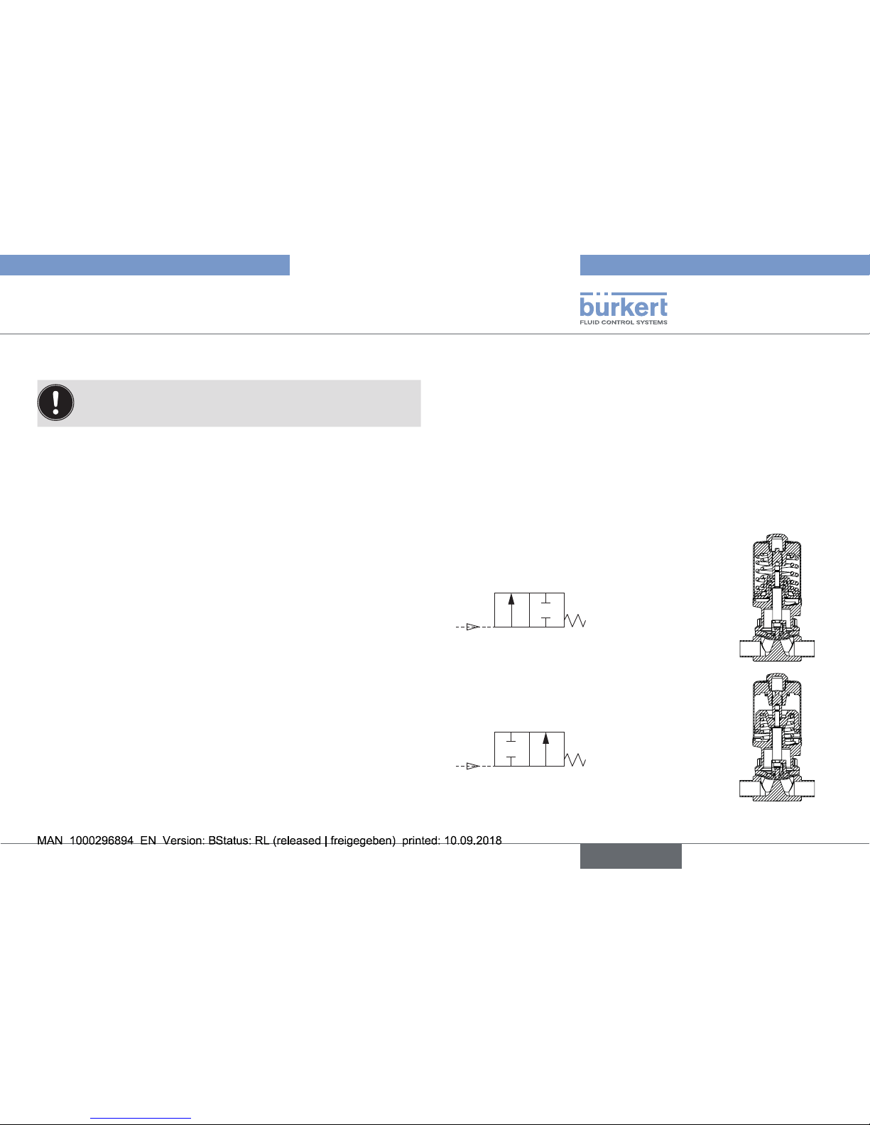
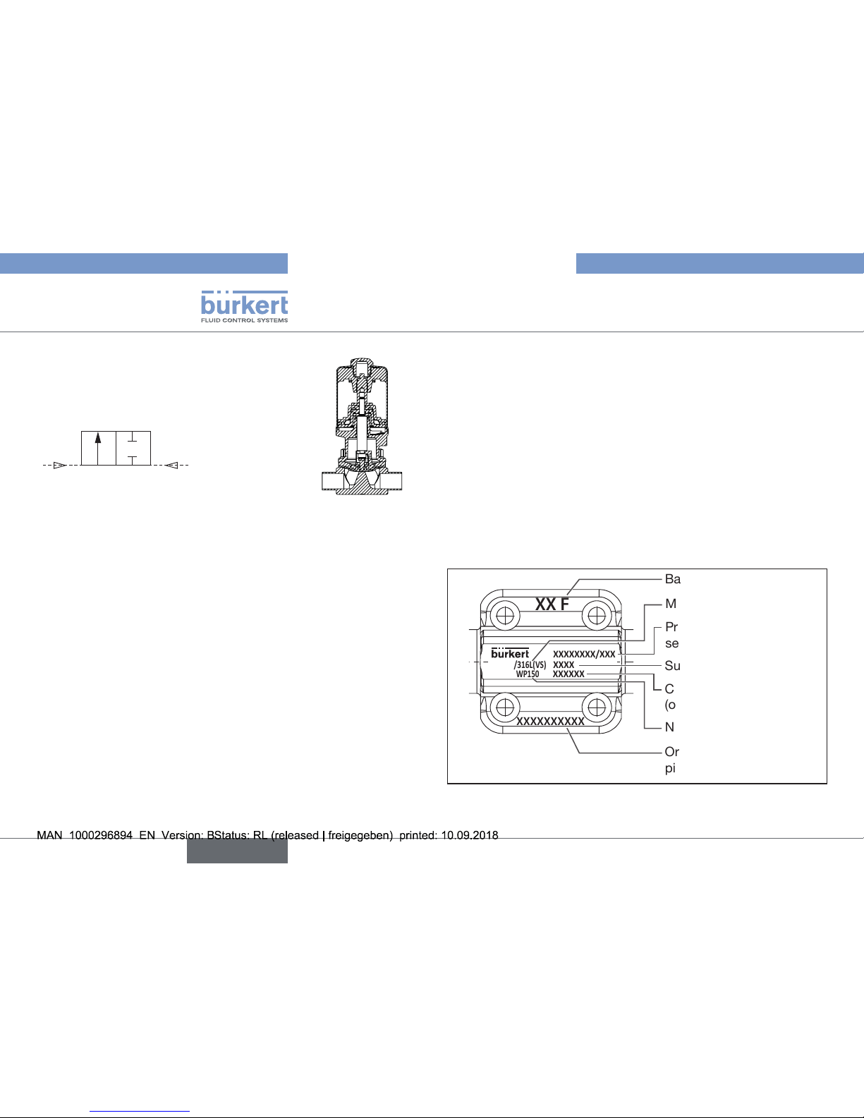
Burkert 2065 User manual

Operating Instructions
Bedienungsanleitung
Manuel d‘utilisation
Type 2063, 2064, 2065
Piston-controlled diaphragm valve
Kolbengesteuertes Membranventil
Vanne à membrane commandée par piston

We reserve the right to make technical changes without notice.
Technische Änderungen vorbehalten.
Sous réserve de modications techniques.
© Bürkert Werke GmbH & Co. KG, 2016 - 2018
Operating Instructions 1809/01_EU-ML_00810533 / Original DE

3
Contents
1 OPERATING INSTRUCTION ................................................. 4
1.1 Denitionofterms ....................................................... 4
1.2 Symbols....................................................................... 4
2 AUTHORISED USE ............................................................... 5
3 BASIC SAFETY INSTRUCTIONS.......................................... 5
4 GENERAL INFORMATION .................................................... 7
4.1 Contact address.......................................................... 7
4.2 Warranty ...................................................................... 7
4.3 InformationontheInternet.......................................... 7
5 PRODUCT DESCRIPTION .................................................... 7
5.1 Structure...................................................................... 7
5.2 Application area........................................................... 9
5.3 Properties .................................................................... 9
5.4 Function....................................................................... 9
6 TECHNICAL DATA............................................................... 10
6.1 Conformity................................................................. 10
6.2 Standards .................................................................. 10
6.3 Labelingoftheforgedbody ...................................... 10
6.4 Labelingofthetubevalvebody(VP)......................... 11
6.5 Type label .................................................................. 11
6.6 Operating conditions ................................................. 12
6.7 General technical data............................................... 19
7 INSTALLATION .................................................................... 19
7.1 Installation position ................................................... 19
7.2 Beforeinstallation...................................................... 20
7.3 Removetheactuatorfromthevalvebody ................ 21
7.4 Installationofthevalvebody..................................... 21
7.5 Installationoftheactuator(weldedbody) ..................... 22
7.6 Pneumatic connection............................................... 23
8 REMOVAL............................................................................ 24
9 MAINTENANCE................................................................... 24
9.1 Maintenance.............................................................. 24
9.2 Repairs ...................................................................... 26
10 MALFUNCTIONS ................................................................ 28
11 REPLACEMENT PARTS...................................................... 29
11.1 Order table ................................................................ 29
12 TRANSPORT, STORAGE, REMOVAL ................................. 30
english
Type 2063, 2064, 2065

4
Operating instruction
1 OPERATING INSTRUCTION
Theoperatinginstructionsdescribetheentirelifecycleofthedevice.
Keep these instructions in a location which is easily accessible
toeveryuserandmaketheseinstructionsavailabletoeverynew
ownerofthedevice.
Important safety information.
Failure to observe these instructions may result in hazardous
situations.
▶The operating instructions must be read and understood.
1.1 Denition of terms
Intheseinstructions,theterm“device”alwaysreferstotheTypes
2063, 2064 and 2065.
1.2 Symbols
DANGER!
Warns of an immediate danger.
▶Failuretoobservethewarningmayresultinafatalorseriousinjury.
WARNING!
Warns of a potentially dangerous situation.
▶Failuretoobservethewarningmay resultin serious injuries
or death.
CAUTION!
Warns of a possible danger.
▶Failuretoobserve this warning may result in a moderateor
minorinjury.
NOTE!
Warns of damage to property.
Important tips and recommendations.
Referstoinformationintheseoperatinginstructionsorin
other documentation.
▶designates an instruction to prevent risks.
→designatesaprocedurewhichyoumustcarryout.
english
Type 2063, 2064, 2065

5
Authorised use
2 AUTHORISED USE
Non-authorized use of the diaphragm valve Type 2063, 2064
and 2065 may be a hazard to people, nearby equipment and
the environment.
▶Thedeviceisdesignedforthecontrolledowofliquid
media.
▶Inareasatriskofexplosion,onlyusedevicesapprovedforusein
thoseareas.ThesedevicesarelabeledwithaseparateExtype
label.Whenutilizedinapotentiallyexplosiveatmosphere,always
payattentiontothedetailsontheseparateExtypelabeland
theExadditionalinstructionscontainedinthescopeofdelivery.
▶During use observe the authorized data, the operating
conditionsandconditionsofusespeciedinthecontract
documents and operating instructions.
▶Thedevicemaybeusedonlyinconjunctionwiththird-party
devices and components recommended and authorized by
Bürkert.
▶Protectdevicefromdamagingenvironmentalinuences
(e.g.radiation,humidity,steam,etc.).Ifanythingisunclear,
consulttherelevantsalesoce.
▶Correct transportation, correct storage and installation and
carefuluseandmaintenanceareessentialforreliableand
faultlessoperation.
▶Theexhaustairmaybecontaminatedwithlubricantsinthe
actuator.
▶Use the device only as intended.
3 BASIC SAFETY INSTRUCTIONS
Thesesafetyinstructionsdonotconsideranycontingenciesorinci-
dentswhichoccurduringinstallation,operationandmaintenance.
Theoperatorisresponsibleforobservingthelocation-specic
safetyregulations,alsowithreferencetothepersonnel.
Danger – high pressure.
▶Beforelooseningthelinesandvalves,turnothepressure
and vent the lines.
Danger of bursting from overpressure.
▶Observethespecicationsonthetypelabelformaximal
control and medium pressure.
▶Observe permitted medium temperature.
Risk of injury from electric shock (when electrical component
installed).
▶Beforereachingintothedeviceortheequipment,switcho
thepowersupplyandsecuretopreventreactivation!
Observeapplicableaccidentpreventionandsafetyregulations
forelectricalequipment!
Risk of injury when opening the actuator!
Theactuatorcontainsatensionedspring.Iftheactuatoris
opened,thereisariskofinjuryfromthespringjumpingout!
▶Do not open the actuator.
english
Type 2063, 2064, 2065

6
Basic safety instructions
Risk of injury from moving parts in the device!
▶Do not reach into openings.
Risk of burns and risk of re if used continuously through hot
device surface.
▶Keepthedeviceawayfromhighlyammablesubstancesand
mediaanddonottouchwithbarehands.
Danger due to loud noises.
▶Depending on the operating conditions, the device may gener-
ateloudnoises.Moredetailedinformationonthelikelihoodof
loudnoisesisavailablefromtherelevantsalesoce.
▶Wearhearingprotectionwheninthevicinityofthedevice.
Leaking medium when the diaphragm is worn.
▶Regularlycheckreliefboreforleakingmedium.
▶Ifmediumisleakingoutofthereliefbore,changethe
diaphragm.
▶Ifthemediaishazardous,protecttheareasurroundingthe
discharge point against dangers.
General hazardous situations.
To prevent injury, ensure:
▶That the system cannot be activated unintentionally.
▶Installationandrepairworkmaybecarriedoutbyauthorized
techniciansonlyandwiththeappropriatetools.
▶Afteraninterruptioninthepowersupplyorpneumatic
supply,ensurethattheprocessisrestartedinadenedor
controlled manner.
▶Thedevicemaybeoperatedonlywheninperfectcondition
andinconsiderationoftheoperatinginstructions.
▶Observethesafetyregulationsspecictotheplantforappli-
cationplanningandoperationofthedevice.
▶Theplantoperatorisresponsibleforthesafeoperationand
handlingoftheplant.
▶Thegeneralrulesoftechnologyapplytoapplicationplanning
andoperationofthedevice.
To prevent damage to property of the device, ensure:
▶Supplythemediaconnectionsonlywiththosemediawhich
arespeciedasowmediainthechapterentitled„6 Technical
data“.
▶Donotputanyloadsonthevalve(e.g.byplacingobjectson
itorstandingonit).
▶Donotmakeanyexternalmodicationstothevalves.Donot
paintthebodypartsorscrews.
▶Donottransport,installorremoveheavydeviceswithoutthe
aidofasecondpersonandusingsuitableauxiliaryequipment.
english
Type 2063, 2064, 2065

7
General information
4 GENERAL INFORMATION
4.1 Contact address
Germany
Bürkert Fluid Control Systems
Sales Center
Christian-Bürkert-Str. 13-17
D-74653Ingelngen
Tel.+49(0)7940-10-91111
Fax+49(0)7940-10-91448
E-mail:[email protected]
International
Contact addresses are found on the nal pages of the printed
operating manual.
InformationontheInternetunder:www.burkert.com
4.2 Warranty
Thewarrantyisonlyvalidifthedeviceisusedasauthorizedin
accordancewiththespeciedapplicationconditions.
4.3 Information on the Internet
Theoperatinginstructionsanddatasheetsfor2063,2064and2065
canbefoundontheInternetat:www.burkert.com
5 PRODUCT DESCRIPTION
5.1 Structure
Piston-controlled diaphragm valve consists of a pneumatically
actuatedpistonactuatoranda2/2-wayvalvebody.Usingneutral
gasesorair(controlmedia),itcontrolstheowofdirty,aggressive,
abrasive, ultrapure or sterile media, even highly viscous media can
beused(owmedia).
5.1.1 2/2-way valve Type 2063
Actuator
Line connection
Valve body
Pilot air port 1 CFA and CFI /
Air discharge connection CFB
Pilot air port 2 CFB and CFI /
Air discharge connection CFA
Transparentcapwith
position indicator
Diaphragm socket
Fig. 1: 2/2-way valve Type 2063, structure and description
english
Type 2063, 2064, 2065

8
Product description
5.1.2 T-valve Type 2064
Actuator
Line connection
T-valve body
Pilot air port 1 CFA and CFI /
Air discharge connection CFB
Pilot air port 2 CFB and CFI /
Air discharge connection CFA
Transparentcapwith
position indicator
Diaphragm socket
Fig. 2: T-valve Type 2064, structure and description
5.1.3 Tank bottom valve Type 2065
Actuator
Line connection
Pilot air port 1 CFA and CFI /
Air discharge connection CFB
Pilot air port 2 CFB and CFI /
Air discharge connection CFA
Transparentcapwith
position indicator
Tankbottomvalvewith
weldingange
VA diaphragm socket
Fig. 3: Tank bottom valve Type 2065, structure and description
english
Type 2063, 2064, 2065

9
Product description
5.2 Application area
Observethemaximum pressurerangeaccordingtothe
type label.
•Dirty, aggressive, abrasive, ultrapure or sterile media.
•Highly viscous media.
5.3 Properties
•Anyowdirection.
•Self-drainingforappropriateinstallation.Theendsoftheuti-
lized connections must be cylindrical.
•Freeofemptyspace.
•Low-turbulenceow.
•Highowvaluesbythestreamlinedvalvebody.
•Maintenance-freeundernormalconditions.
•Diaphragms can be easily replaced.
5.3.1 Options
•Strokelimit(asmax.ormin./max.design)
Adjustingscrewusedtolimitopenpositionofvalve,thereby
alsolimitingtheowrate.
•Feedback indicator
Providesfeedbackonvalvepositionusinginductiveproximity
switchortype8697feedbackindicator.
5.3.2 Device versions
Thepiston-controlleddiaphragmvalveisavailableforthefollowing
actuatorsizes:ø50mm,ø70mm,ø90mm,ø130mm.
5.4 Function
Springforce(CFA)orpneumaticpilotpressure(CFBandCFI)gen-
eratestheclosingforceonthediaphragmpressurepiece.Theforce
istransferredviaaspindlewhichisconnectedtotheactuatorpiston.
5.4.1 Control functions (CF)
Control function A (CFA)
Normally closed by spring action
Control function B (CFB)
Normally open by spring action
english
Type 2063, 2064, 2065

10
Technical data
Control function I (CFI)
Actuatingfunctionviareciprocal
pressurization
6 TECHNICAL DATA
6.1 Conformity
TheType2063,2064and2065conformswiththeEUDirectives
accordingtotheEUDeclarationofConformity.
6.2 Standards
The applied standards, which verify conformity with the EU
Directives,canbefoundontheEU-TypeExaminationCerticate
and/ortheEUDeclarationofConformity.
6.3 Labeling of the forged body
XXXXXXXXXX
XX F
1.4435/316L(VS)
PN16/CWP150
XXXXXXXX/XXX
XXXXXX
XXXX
Surfacequalitycode
Customer-specictext
(optional)
Oriceconnectionand
pipe dimension
Batch number
Material
Production number /
serial number
Nominal pressure
Fig. 4: Labeling of the forged body
english
Type 2063, 2064, 2065

11
Technical data
6.4 Labeling of the tube valve body
(VP)
1.4435
316L(VP)
XXXXXXXX
XXXXXXXXXX
PN16 / CWP150
XXXXXXXX / XXX
XXXX / XXXXXX
Material HeatCompany logo
Nominal
pressure
Connectionorice
and pipe dimensions
Surfacequalitycode/
Customer-specictext
(optional)
Production number /
serial number
Fig. 5: Labeling of the tube valve body (VP)
6.5 Type label
WARNING!
Risk of injury from high pressure.
Excessivepressurecandamagethedevice.
▶Complywithpressurerangevaluesonthetypelabel.
Made in Germany
00999999
W28UU
Pilot 5.0-10bar
D33.7 Pmed 6bar
2063 A 25,0 PTFE VS
Orice
Seal material
Body material
Controlfunction(SF)
Type
Permitted medium pressure
Identicationnumberofthedevice,
Dateofmanufacture
CEidentication(ifapplicable)
Port connection,
Permitted medium pressure
Fig. 6: Description of the type label (Example)
english
Type 2063, 2064, 2065

12
Technical data
6.6 Operating conditions
6.6.1 Temperature ranges
Permitted ambient temperature for actuator
Actuator sizes Actuator material Ambient temperature
ø50mm
Stainless steel 0...+80°C
ø70mm
ø90mm
ø130mm
Tab. 1: Ambient temperature for actuator
Permitted medium temperature for bodies
Body material Medium
temperature
Castbody(VG) 1.4435(AISI316L)
-10...+150°C
Forgedbody(VS)
1.4435BN2(AISI316L)
according to
ASMEBPE1997
Tube valve body
(VP) 1.4435BN2(AISI316L)
Tab. 2: Medium temperature for bodies
Permitted medium temperature for diaphragms
The indicated medium temperatures apply only to media
whichdonotcorrodeorswellthediaphragmmaterials.
Thebehaviorofthemediumwithrespecttothediaphragm
may be changed by the medium temperature.
Thefunctionproperties,inparticulartheservicelifeofthe
diaphragm, may deteriorate if the medium temperature
increases.
Donotusethediaphragmsassteamshut-oelement.
Material Temperature Remarks
EPDM
(AB)
-10...+130°C Steam sterilization up to
+140°C/60min
EPDM
(AD)
-10...+143°C Steam sterilization up to
+150°C/60min
FKM
(FF)
0...+130°C No steam / dry heat up to
+150°C/60min
PTFE
(EA)
-10...+130°C Steam sterilization up to
+140°C/60min
Advanced
PTFE(EU)
-5...+143°C Steam sterilization up to ‘
+150°C/60min
Gylon
(ER)
-5...+130°C Steam sterilization up to
+140°C/60min
Tab. 3: Permitted medium temperature for diaphragms
english
Type 2063, 2064, 2065

13
Technical data
6.6.2 Pressure ranges
Maximum pilot pressure
Actuator size Actuator material Max. pilot pressure
ø50mm
Stainless steel 10.5 bar
ø70mm
ø90mm
ø130mm 7 bar
Tab. 4: Maximum pilot pressure
Pilot pressure for control function A
Actuator
size
[mm]
Orice
DN (diaphragm
size) [mm]
Pilot pressure [bar]
for medium pressure
0 bar maximal
ø50 15 5.4 5.0
ø70 4.8 4.5
ø70 20 4.8 4.5
ø70 25 5.5 4.3
ø90 5.0 4.0
ø90 32 5.0 4.5
ø90 40 5.0 4.5
ø130 5.0 4.6
ø130 50 5.0 4.8
Tab. 5: Pilot pressure for control function A
Operating pressure for control function A
Thevaluesapplytobodymadeof
•forgedsteel(VS)
•precisioncasting(VG)
•tubevalvebody(VP)
Actuator size
[mm]
Orice DN
(diaphragm size)
[mm]
Max. sealed medium pressure [bar]
Pressure on one
side
Pressure on both
sides
EPDM/FKM PTFE EPDM/FKM PTFE
ø50 15 8.5 5 5 3.5
ø70 10 10 10 10
ø70 20 10 10 10 7.5
ø70 25 6.5 4.5 5.5 3.5
ø90 10 810 7
ø90 32 86 6 4
ø90 40 5.5 5 4 3
ø130 10 10 10 9
ø130 50 10 7 7 5
Tab. 6: Operating pressure for control function A
english
Type 2063, 2064, 2065

14
Technical data
Required minimum pilot pressure depending on medium
pressure
Thefollowinggraphsillustratetherequiredminimumpilot
pressuredependingonthemediumpressureforcontrolfunc-
tions B and I.
Thevaluesapplytobodymadeof
•forgedsteel(VS)
•precisioncasting(VG)
•tubevalvebody(VP)
Control function B / elastomer diaphragm
Pilot pressure [bar]
Medium pressure [bar]
ø 50 CFB
EPDM
0123456789 10
0
2
4
6
8
10
12
14
16
DN15
Fig. 7: Pressure graph, actuator ø 50 mm, control function B,
elastomer diaphragm
Pilot pressure [bar]
Medium pressure [bar]
ø 70 CFB
EPDM
0123456789 10
0
2
4
6
8
10
12
14
16
DN15
DN20
DN25
Fig. 8: Pressure graph, actuator ø 70 mm, control function B,
elastomer diaphragm
Pilot pressure [bar]
Medium pressure [bar]
ø 90 CFB
EPDM
0123456789 10
0
2
4
6
8
10
12
14
16
DN40
DN25
Fig. 9: Pressure graph, actuator ø 90 mm, control function B,
elastomer diaphragm
english
Type 2063, 2064, 2065

15
Technical data
Pilot pressure [bar]
Medium pressure [bar]
ø 130 CFB
EPDM
0123456789 10
0
2
4
6
8
10
12
14
16
DN50
DN40
Fig. 10: Pressure graph, actuator ø 130 mm, control function B,
elastomer diaphragm
Control function B / PTFE elastomer diaphragm
Pilot pressure [bar]
Medium pressure [bar]
ø 50 CFB
PTFE/EPDM
0123456789 10
0
2
4
6
8
10
12
14
16
DN15
Fig. 11: Pressure graph, actuator ø 50 mm, control function B,
PTFE elastomer diaphragm
Pilot pressure [bar]
Medium pressure [bar]
ø 70 CFB
PTFE/EPDM
0123456789 10
0
2
4
6
8
10
12
14
16
DN15
DN20
DN25
Fig. 12: Pressure graph, actuator ø 70 mm, control function B,
PTFE elastomer diaphragm
english
Type 2063, 2064, 2065

16
Technical data
Pilot pressure [bar]
Medium pressure [bar]
ø 90 CFB
PTFE/EPDM
0123456789 10
0
2
4
6
8
10
12
14
16
DN40
DN25
Fig. 13: Pressure graph, actuator ø 90 mm, control function B,
PTFE elastomer diaphragm
Pilot pressure [bar]
Medium pressure [bar]
ø 130 CFB
PTFE/EPDM
0123456789 10
0
2
4
6
8
10
12
14
16
DN50
DN40
Fig. 14: Pressure graph, actuator ø 130 mm, control function B,
PTFE elastomer diaphragm
Control function I / elastomer diaphragm
Pilot pressure [bar]
Medium pressure [bar]
ø 50 CFI
EPDM
0123456789 10
0
2
4
6
8
10
12
14
16
DN15
Fig. 15: Pressure graph, actuator ø 50 mm, control function I,
elastomer diaphragm
Pilot pressure [bar]
Medium pressure [bar]
ø 70 CFI
EPDM
0123456789 10
0
2
4
6
8
10
12
14
16
DN15
DN20
DN25
Fig. 16: Pressure graph, actuator ø 70 mm, control function I,
elastomer diaphragm
english
Type 2063, 2064, 2065

17
Technical data
Pilot pressure [bar]
Medium pressure [bar]
ø 90 CFI
EPDM
0123456789 10
0
2
4
6
8
10
12
14
16
DN25
DN40
Fig. 17: Pressure graph, actuator ø 90 mm, control function I,
elastomer diaphragm
Pilot pressure [bar]
Medium pressure [bar]
ø 130 CFI
EPDM
0123456789 10
0
2
4
6
8
10
12
14
16
DN40
DN50
Fig. 18: Pressure graph, actuator ø 130 mm, control function I,
elastomer diaphragm
Control function I / PTFE elastomer diaphragm
Pilot pressure [bar]
Medium pressure [bar]
ø 50 CFI
PTFE
0123456789 10
0
2
4
6
8
10
12
14
16
DN15
Fig. 19: Pressure graph, actuator ø 50 mm, control function I,
PTFE elastomer diaphragm
Pilot pressure [bar]
Medium pressure [bar]
ø 70 CFI
PTFE
0123456789 10
0
2
4
6
8
10
12
14
16
DN15
DN20
DN25
Fig. 20: Pressure graph, actuator ø 70 mm, control function I,
PTFE elastomer diaphragm
english
Type 2063, 2064, 2065

18
Technical data
Pilot pressure [bar]
Medium pressure [bar]
ø 90 CFI
PTFE
0123456789 10
0
2
4
6
8
10
12
14
16
DN25
DN40
Fig. 21: Pressure graph, actuator ø 90 mm, control function I,
PTFE elastomer diaphragm
Pilot pressure [bar]
Medium pressure [bar]
ø 130 CFI
PTFE
0123456789 10
0
2
4
6
8
10
12
14
16
DN40
DN50
Fig. 22: Pressure graph, actuator ø 130 mm, control function I,
PTFE elastomer diaphragm
6.6.3 Flow value
Diaph-
ragm
size
Line
connection
Kv value forged [m3/h]1)
[mm] [Zoll]
DIN EN ISO
1127
ISO 4200
DIN 11866
RB
DIN 11850 R2
DIN 11866 RA
DIN EN 10357
RA
ASME
BPE
DIN
11866
RC
15 15 1/2“ 6.5 6.5 3.1
20 20 3/4“ 12.5 12.4 8.4
25 25 1“ 18 20 15.5
40 40 1 1/2“ 41 40 37
50 50 2“ 66 66 66
Tab. 7: Kv value for forged valve body
1) Values determined with forged valve body and elastomer dia-
phragm:
measurement at 20°C, 1bar pressure at valve inlet and free
outlet.
english
Type 2063, 2064, 2065

19
Installation
6.7 General technical data
Actuator size see type label
Controlfunction seetypelabel.Descriptionofcontrolfunc-
tions see chapter „5.4.1“
Installation
Type2063,2064 atwill,preferablyactuatorinuprightposition
Type2065 preferablywiththeactuatortothebottom
(tankbottomvalve)
Media:
Control media neutral gases, air
Flowmedia liquids;ultrapure,sterile,aggressiveor
abrasive media
Materials
Body
Type2063 precisioncasting(VG),forgedsteel(VS),
tubevalvebody(VP)
Type 2064, 2065 stainless steel block material
Actuator stainless steel
Sealingelements FKMandEPDM
Diaphragm EPDM,PTFE,FKM
Connections
Pilotairports stainlesssteelthreadedbushingG1/8
Mediumconnection weldend:inaccordancewithENISO1127
(ISO4200),DIN11850R2
otherconnectionsonrequest
7 INSTALLATION
DANGER!
Danger - high pressure.
▶Beforedismountingthelinesandvalves,turnothepressure
and vent the lines.
WARNING!
Risk of injury from improper installation.
▶Installationmayonlybeperformedbyqualiedandtrained
personnel.
▶Useanopen-endwrenchfortheassembly.
▶Followingassembly,performacontrolledrestart.
For control function I – Danger if pilot pressure fails.
ForcontrolfunctionIcontrolandresettingoccurpneumatically.
Ifthepressurefails,nodenedpositionisreached.
▶Toensureacontrolledrestart,rstpressurizethedevicewith
pilotpressure,thenswitchonthemedium.
7.1 Installation position
Dependingonthevalvebody,theinstallationpositionofthedia-
phragmvalveisdierent.
Installation for self-drainage of the body
Itistheresponsibilityoftheinstallerandoperatorto
ensureself-drainage.
english
Type 2063, 2064, 2065

20
Installation
Installation for leakage detection
Oneoftheboresinthediaphragmsocketformoni-
toringleakagemustbeatthelowestpoint.
7.1.1 Installation position 2-way body
Type 2063
Installationposition:atwill,preferablywiththeactuatorupright.
Toensureself-drainage:
→Install valve body inclined by an angle α=10°to40°tothe
horizontal.
Forgedandcastbody:Markonthevalvebodymustpoint
upwards(12o’clockposition,see„Fig. 23“).
→Observeaninclinationangleof1°–5°tothelineaxis.
Angle α:10°to40°
Inclinationtothelineaxis1°...5°
Mark
α
Fig. 23: Installation position for self-drainage of the valve body
7.1.2 Installation position T-valve body Type
2064
FortheinstallationoftheT-valvesintocircularpipelines,werec-
ommendthefollowinginstallationpositions:
Whenmediaissupplied: Whenmediaisremoved:
Fig. 24: Installation position type 2064
7.1.3 Installation position tank bottom body
Type 2065
Preferablywiththeactuatortothebottom.
7.2 Before installation
•Ensurethepipelinesareush..
•Theowdirectionisoptional.
7.2.1 Preparatory work
→Cleanpipelines(sealingmaterial,swarf,etc.).
→Support and align pipelines.
english
Type 2063, 2064, 2065
This manual suits for next models
2
Table of contents
Other Burkert Control Unit manuals

Burkert
Burkert 3280 User manual

Burkert
Burkert 6027 User manual

Burkert
Burkert 2012 User manual

Burkert
Burkert 0312 User manual

Burkert
Burkert 8640 User manual

Burkert
Burkert 2832 User manual

Burkert
Burkert 5470 User manual

Burkert
Burkert 0142 User manual

Burkert
Burkert Type 2000 User manual

Burkert
Burkert 2301 Series User manual

Burkert
Burkert 6228 User manual

Burkert
Burkert 2100 series User manual

Burkert
Burkert 0250 User manual

Burkert
Burkert 8691 User manual

Burkert
Burkert 0258 User manual

Burkert
Burkert 0406 User manual

Burkert
Burkert 0301 User manual

Burkert
Burkert 8630 User manual

Burkert
Burkert 2030 User manual

Burkert
Burkert 2100 series User manual