manuals.online logo
Brands
  1. Home
  2. •
  3. Brands
  4. •
  5. Monacor
  6. •
  7. Control Unit
  8. •
  9. Monacor ATT-412PEU User manual

Monacor ATT-412PEU User manual

ELECTRONICS FOR SPECIALISTS ELECTRONICS FOR SPECIALISTS ELECTRONICS FOR SPECIALISTS ELECTRONICS FOR SPECIALISTS ELECTRONICS FOR SPECIALISTS ELECTRONICS
ATT-412PEU Bestell-Nr. •Order No. 17.1460
ATT-424PEU Bestell-Nr. •Order No. 17.1470
MONACOR INTERNATIONAL GmbH & Co. KG • Zum Falsch 36 • 28307 Bremen • Germany
Copyright©by MONACOR INTERNATIONAL. All rights reserved. A-0293.99.03.04.2019
ATT-4 . . PEU
volume
OUTPUT
program
100 V
G 1
P
0
24V(⎓
)
wichtige Durchsagen
important
annoucements
24 V/80 mA
-
15 dB
-
18 dB
-
21 dB
-
27 dB
-
33 dB
-
∞dB
-
12 dB
-
9 dB
-
6 dB
-
3 dB
0 dB 10
0
1
6
1
6
1A
2A
3A
4A
5A
6A
1B
2B
3B
4B
5B
6B
E
P
Notfalltaste
Emergency switch
S
2 × 1N4001
ELA-Lautsprecher
PA speaker
ATT-412PEU: max. 10 W
ATT-424PEU: max. 20 W
100-V-Eingänge
100 V inputs
Program(m) 1
Program(m) 2
Program(m) 3
Program(m) 4
Program(m) 5
Program(m) 6
PA Attenuator with Program Selector
These instructions are intended for installers with
knowledge in 100V technology for PA applica-
tions. Please read the instructions carefully prior
to installation and keep them for later reference.
1 Applications
The attenuator with program selector is specially de-
signed for use in PA systems operating with 100V tech-
nology. The maximum power rating by the following
speaker or by the following speaker group must not be
exceeded – see specifications.
The attenuator must be installed into a standard
flush-mounting socket or into a surface-mounting socket
(e.g. MONACOR ATT-400).
2 Safety Notes
The unit corresponds to all relevant directives of the EU
and is therefore marked with .
•
The unit is suitable for indoor use only. Protect it against
dripping water and splash water, high air humidity and
heat (admissible ambient temperature range 0– 40 °C).
•
Speaker cables are susceptible to electrical interference.
Therefore, it is recommended to lay them at a distance
of several metres to any sources of interference (e.g.
dimmers, light switches).
•
For cleaning only use a dry, soft cloth; never use chem-
icals or water.
•
No guarantee claims for the unit and no liability for
any resulting personal damage or material damage will
be accepted if the unit is used for other purposes than
originally intended, if it is not connected in an expert
way, or if it is overloaded.
If the unit is to be put out of operation defini-
tively, take it to a local recycling plant for a dis-
posal which is not harmful to the environment.
3 Electrical Connection
WARNING During operation, there is a hazard of con-
tact with a voltage of up to 100V at the
connections. Installation must be carried
out by skilled personnel only.
Pay attention to the correct power matching. An overload
will damage the power amplifier and of the attenuator!
1) If the PA system is switched on, switch it off completely
first!
2) To facilitate handling, the terminals can be removed
from their plug-in connections.
3) Connect the lines of the 100V signal sources to the
inputs “1A” to “6A” (positive poles) and “1B” to “6B”
(negative poles).
4) Connect the PA speaker to the terminals “OUTPUT”.
5) By activating the emergency priority relay (G1), im-
portant announcements can be heard via the speaker
connected, regardless of the position of the program
selector and even if the attenuator is set to zero:
a) Separate the jumper “P”.
b) To activate the relay, connect the 24 V control line
to the terminals “+” and “–”.
c) If the important announcements are made via a
separate amplifier, connect the 100V output of this
amplifier to the terminals “P” (positive pole) and
“E” (negative pole).
If the important announcements are made via
an amplifier which also amplifies a music program,
additionally connect the output of this amplifier to
the terminals “P” (positive pole) and “E” (negative
pole) [also see broken lines in the figure: example
of an amplifier which amplifies program 6 and im-
portant announcements].
4 Specifications
Frequency range: . . . . . . . .50–18 000 Hz
Power rating: . . . . . . . . . . .12W – ATT-412PEU
24W – ATT-424PEU
Emergency priority relay:. .24V(⎓), 80 mA
Ambient temperature:. . . .0–40°C
Dimensions: (W ×H ×D):. .80 ×154 ×68mm
Mounting depth: . . . . . . . .< 50mm
Subject to technical modification.
ELA-Lautstärkesteller mit Programmwähler
Diese Anleitung richtet sich an Installateure mit
Fachkenntnissen in der 100-V-Beschallungstech-
nik. Bitte lesen Sie die Anleitung vor der Instal-
lation gründlich durch und heben Sie sie für ein
späteres Nachlesen auf.
1 Verwendungsmöglichkeiten
Der Lautstärkesteller mit Programmwähler ist spezi-
ell für den Einsatz in ELA-Anlagen konzipiert, die mit
100-V-Technik arbeiten. Die maximale Nennbelastbarkeit
durch den nachfolgenden Lautsprecher bzw. durch die
nachfolgende Lautsprechergruppe darf nicht überschrit-
ten werden – siehe Technischen Daten.
Der Lautstärkesteller muss in eine Standard-Unter-
putzdose oder in eine Aufputzdose (z.B. ATT-400 von
MONACOR) eingesetzt werden.
2 Hinweise für den sicheren Gebrauch
Das Gerät entspricht allen relevanten Richtlinien der EU
und trägt deshalb das -Kennzeichen.
•
Das Gerät ist nur zur Verwendung im Innenbereich
geeignet. Schützen Sie es vor Tropf- und Spritzwas-
ser, hoher Luftfeuchtigkeit und Hitze (zulässiger Ein-
satztemperaturbereich 0– 40 °C).
•
Lautsprecherleitungen können elektrische Störungen
auffangen. Darum sollten sie nur im Abstand von eini-
gen Metern zu Störquellen (z.B. Dimmer, Lichtschalter)
verlegt werden.
•
Verwenden Sie für die Reinigung nur ein trockenes,
weiches Tuch, auf keinen Fall Chemikalien oder Wasser.
•
Wird das Gerät zweckentfremdet, nicht fachgerecht
angeschlossen oder überlastet, kann keine Haftung für
daraus resultierende Sach- oder Personenschäden und
keine Garantie für das Gerät übernommen werden.
Soll das Gerät endgültig aus dem Betrieb ge-
nommen werden, übergeben Sie es zur umwelt-
gerechten Entsorgung einem örtlichen Recy-
clingbetrieb.
3 Elektrischer Anschluss
WARNUNG Im Betrieb liegt berührungsgefährliche
Spannung bis 100V an den Anschlüssen
an. Die Installation darf nur durch Fach-
personal erfolgen.
Achten Sie auf die richtige Leistungsanpassung. Eine
Überlastung führt zur Beschädigung der Verstärker-
Endstufe und des Lautstärkestellers!
1) Falls die ELA-Anlage eingeschaltet ist, diese zuerst
komplett ausschalten!
2) Zur besseren Handhabung lassen sich die Anschluss-
klemmen von ihren Steckverbindungen abziehen.
3) Die Leitungen der 100-V-Signalquellen an die Ein-
gänge „1A“ bis „6A“ (Pluspole) und „1B“ bis „6B“
(Minuspole) anschließen.
4) Den ELA-Lautsprecher an die Klemmen „OUTPUT“ an-
schließen.
5) Durch Aktivieren des Pflichtempfangsrelais (G1) kön-
nen wichtige Durchsagen über den angeschlossenen
Lautsprecher gehört werden, auch wenn der Lautstär-
kesteller auf Null steht und unabhängig von der Stel-
lung des Programmwählers:
a) Die Drahtbrücke „P“ durchtrennen.
b) Die 24-V-Steuerleitung zur Aktivierung des Relais
an die Klemmen „+“ und „–“ anschließen.
c) Erfolgen die wichtigen Durchsagen über einen
separaten Verstärker, dessen 100-V-Ausgang mit
den Klemmen „P“ (Pluspol) und „E“ (Minuspol)
verbinden.
Erfolgen die wichtigen Durchsagen über einen
Verstärker, über den auch ein Musikprogramm
läuft, dessen Ausgang zusätzlich an die Klemmen
„P“ (Pluspol) und „E“ (Minuspol) anschließen (siehe
auch gestrichelte Leitungen in der Abb.: Beispiel für
einen Verstärker, über den Programm 6 und wich-
tige Durchsagen laufen).
4 Technische Daten
Frequenzbereich: . . . . . . . .50–18 000 Hz
Nennbelastbarkeit:. . . . . . .12W – ATT-412PEU
24W – ATT-424PEU
Pflichtempfangsrelais: . . . .24V(⎓), 80 mA
Einsatztemperatur:. . . . . . .0–40 °C
Abmessungen (B ×H ×T): .80 ×154 ×68mm
Einbautiefe: . . . . . . . . . . . .< 50mm
Änderungen vorbehalten.
English Deutsch
ELECTRONICS FOR SPECIALISTS ELECTRONICS FOR SPECIALISTS ELECTRONICS FOR SPECIALISTS ELECTRONICS FOR SPECIALISTS ELECTRONICS FOR SPECIALISTS ELECTRONICS
MONACOR INTERNATIONAL GmbH & Co. KG • Zum Falsch 36 • 28307 Bremen • Germany
Copyright©by MONACOR INTERNATIONAL. All rights reserved. A-0293.99.03.04.2019
ATT-4 . . PEU
volume
OUTPUT
program
100 V
G 1
P
0
24V(⎓
)
wichtige Durchsagen
important
annoucements
24 V/80 mA
-
15 dB
-
18 dB
-
21 dB
-
27 dB
-
33 dB
-
∞dB
-
12 dB
-
9 dB
-
6 dB
-
3 dB
0 dB 10
0
1
6
1
6
1A
2A
3A
4A
5A
6A
1B
2B
3B
4B
5B
6B
E
P
Notfalltaste
Emergency switch
S
2 × 1N4001
ELA-Lautsprecher
PA speaker
ATT-412PEU: max. 10 W
ATT-424PEU: max. 20 W
100-V-Eingänge
100 V inputs
Program(m) 1
Program(m) 2
Program(m) 3
Program(m) 4
Program(m) 5
Program(m) 6
ATT-412PEU Référence num. • Codice 17.1460
ATT-424PEU Référence num. • Codice 17.1470
Attenuatore PA con selettore di programmi
Queste istruzioni sono rivolte agli installatori che
possiedono delle conoscenze specifiche della tec-
nica di sonorizzazione a 100V. Vi preghiamo di
leggerle attentamente prima dell‘installazione e
di conservarle per un uso futuro.
1 Possibilità d’impiego
L’attenuatore con selettore di programmi è stato realiz-
zato specialmente per l’impiego in impianti PA che la-
vorano con uscita audio 100V. Non si deve superare la
potenza nominale massima con l’altoparlante o il gruppo
di altoparlanti a valle – vedi di dati tecnici.
L’attenuatore deve essere montato in una scatola
standard da incasso oppure in una a muro (p.es. ATT-400
di MONACOR).
2 Avvertenze di sicurezza
Quest’apparecchio è conforme a tutte le direttive rile-
vanti dell’UE e pertanto porta la sigla .
•
Lo strumento è previsto solo per l’uso all’interno di lo-
cali. Proteggerlo dall’acqua gocciolante e dagli spruzzi
d’acqua, da alta umidità dell’aria e dal calore (tempe-
ratura d’impiego ammessa fra 0 e 40°C).
•
I cavi per altoparlanti possono captare dei disturbi elet-
trici. Perciò è opportuno sistemarli a distanza di alcuni
metri da fonti di disturbi (p.es. dimmer, interruttori
della luce).
•
Per la pulizia usare solo un panno morbido, asciutto;
non impiegare in nessun caso prodotti chimici o acqua.
•
Nel caso d’uso improprio, di collegamenti sbagliati o
di sovraccarico dell’apparecchio, non si assume nessuna
responsabilità per eventuali danni consequenziali a
persone o a cose e non si assume nessuna garanzia per
lo strumento.
Se si desidera eliminare l’apparecchio definitiva-
mente, consegnarlo per lo smaltimento ad un’i-
stituzione locale per il riciclaggio.
3 Collegamento elettrico
AVVERTIMENTO Durante il funzionamento, ai contatti
è presente una tensione pericolosa
fino a 100V. L’installazione deve essere
fatta solo da personale qualificato.
Fare attenzione al corretto adattamento della potenza.
Il sovraccarico provoca il danneggiamento dello stadio
finale dell’amplificatore e dell’attenuatore!
1) Se l’impianto PA è acceso, spegnerlo prima comple-
tamente!
2) Per facilitare le manovre, i morsetti possono essere
staccati dai connettori.
3) Collegare i cavi delle sorgenti di segnali 100 V con gli
ingressi “1A” a “6A” (poli positivi) e “1B” a “6B” (poli
negativi).
4) Collegare l’altoparlante PA con i morsetti “OUTPUT”.
5) Attivando il relè prioritario (G1) è possibile fare avvisi
importanti tramite l’altoparlante collegato anche se
l’attenuatore si trova sullo zero e indipendentemente
dalla posizione del selettore di programmi:
a) Tagliare il ponticello “P”.
b) Collegare il cavo di comando 24V con i morsetti “+”
e “–” per attivare il relè.
c) Se gli avvisi importanti sono fatti tramite un amplifi-
catore separato, collegare l’uscita 100V di quest’ul-
timo con i morsetti “P” (positivo) e “E” (negativo).
Se gli avvisi importanti sono fatti tramite un
amplificatore che gestisce anche un programma di
musica, collegare l’uscita di quest’ultimo in più con
i morsetti “P” (positivo) e “E” (negativo) [vedi anche
le linee tratteggiate nell’illustrazione: esempio per
un amplificatore che gestisce il programma 6 non-
ché avvisi importanti].
4 Dati tecnici
Gamma di frequenze: . . . .50–18000 Hz
Potenza nominale: . . . . . . .12W – ATT-412PEU
24W – ATT-424PEU
Relè prioritario: . . . . . . . . .24V(⎓), 80 mA
Temperatura d’esercizio: . .0 –40°C
Dimensioni (l ×h ×p): . . . .80 ×154 ×68 mm
Profondità di montaggio: .< 50 mm
Con riserva di modifiche tecniche.
Atténuateur Public Adress
avec sélecteur de programme
Cette notice s’adresse aux installateurs possédant
des connaissances en technique de sonorisation
ligne 100V. Veuillez lire la présente notice avec
attention avant l‘installation et conservez-la pour
pouvoir vous y reporter ultérieurement.
1 Possibilités d’utilisation
L’atténuateur avec sélecteur de programme est spécia-
lement conçu pour une utilisation dans les systèmes de
Public Adress avec technique ligne 100V. La puissance no-
minale maximale par le haut-parleur suivant ou le groupe
de haut-parleurs suivants ne doit pas être dépassée : voir
caractéristiques techniques.
L’atténuateur doit être placé dans une prise standard
encastrée ou dans une prise en saillie (p.ex. ATT-400 de
MONACOR).
2 Conseils d’utilisation et de sécurité
L’appareil répond à toutes les directives nécessaires de
l’Union européenne et porte donc le symbole .
•
L’appareil n’est conçu que pour une utilisation en in-
térieur. Protégez-le des éclaboussures, de tout type de
projections d’eau, de l’humidité élevée et de la chaleur
(température ambiante admissible 0– 40 °C).
•
Les câbles haut-parleurs sont sensibles aux interfé-
rences électriques. Il convient de les placer à une dis-
tance de quelques mètres des sources d’interférences
(p.ex. dimmers, interrupteurs lumineux).
•
Pour le nettoyage, utilisez un chiffon sec et doux, en
aucun cas de produits chimiques ou d’eau.
•
Nous déclinons toute responsabilité en cas de dom-
mages corporels ou matériels résultants si l’appareil est
utilisé dans un but autre que celui pour lequel il a été
conçu, s’il n’est pas correctement branché ou s’il y a
surcharge ; de même, la garantie deviendrait caduque.
Lorsque l’appareil est définitivement retiré du
service, vous devez le déposer dans une usine
de recyclage de proximité pour contribuer à son
élimination non polluante
3 Branchement électrique
AVERTISSEMENT Pendant le fonctionnement, une ten-
sion de 100V au plus est présente aux
bornes ! Seul un technicien spécialisé
est habilité à effectuer l’installation.
Faites attention à l’adaptation correcte de la puissance.
Une surcharge peut endommager l‘amplificateur et
l’atténuateur !
1) Si l’installation de Public Adress est allumée, étei-
gnez-la tout d’abord complètement.
2) Pour une meilleure manipulation, il est possible de re-
tirer les bornes de branchement de leur emplacement.
3) Reliez les câbles des sources de signal 100 V aux entrées
«1A»à «6A» (pôles plus) et «1B» à «6B» (pôles moins).
4) Connectez le haut-parleur Public Adress aux bornes
«OUTPUT».
5) Par l’activation du relais prioritaire d’urgence (G1),
des annonces importantes peuvent être entendues via
le haut-parleur relié même si l’atténuateur est sur la
position zéro et indépendamment de la position du
sélecteur de programme :
a) Séparez le cavalier «P».
b) Reliez le câble de commande 24V aux bornes «+» et
«–» pour activer le relais.
c) En cas d’annonces importantes effectuées via un
amplificateur distinct, reliez sa sortie 100V aux
bornes «P» (pôles plus) et «E» (pôle moins).
En cas d’annonces importantes effectuées via un
amplificateur diffusant également un programme
de musique, reliez en plus sa sortie aux bornes «P»
(pôle plus) et «E» (pôle moins) [voir également les
liaisons interrompues sur le schéma : exemple d’un
amplificateur via lequel s’effectue le programme 6
et les annonces importantes].
4 Caractéristiques techniques
Bande passante : . . . . . . . .50– 18 000 Hz
Puissance nominale : . . . . .12 W – ATT-412PEU
24W – ATT-424PEU
Relais prioritaire :. . . . . . . .24 V (⎓), 80mA
Température de fonc. : . . .0–40°C
Dimensions (l ×h ×p) : . . .80 ×154 ×68 mm
Profondeur de montage : .< 50 mm
Tout droit de modification réservé.
CARTONS ET EMBALLAGE
PAPIER À TRIER
Italiano Français
This manual suits for next models

3

Other Monacor Control Unit manuals

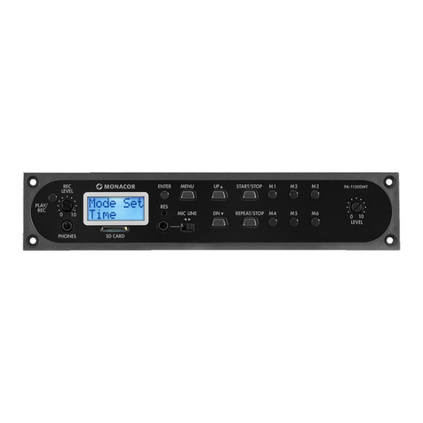
Monacor PA-1120DMT User manual

Monacor

Monacor PA-1120DMT User manual

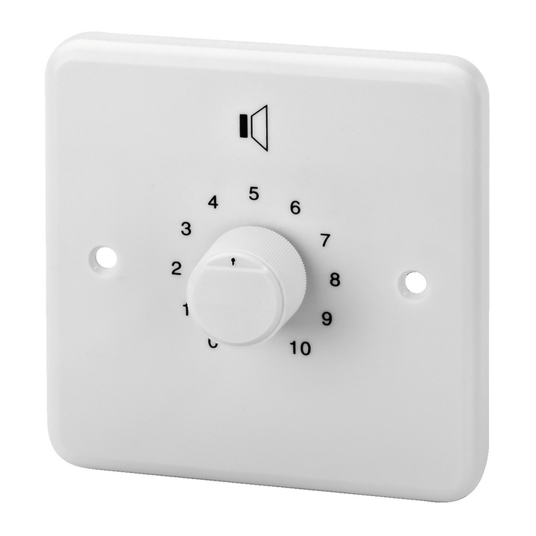
Monacor ATT-212H/WS User manual

Monacor

Monacor ATT-212H/WS User manual

Monacor DMP-100R User manual

Monacor

Monacor DMP-100R User manual

Monacor DN-1218P User manual

Monacor

Monacor DN-1218P User manual

Monacor ATT-324PEU User manual

Monacor

Monacor ATT-324PEU User manual

Monacor ATT-325ST User manual

Monacor

Monacor ATT-325ST User manual

Monacor ATT-210P/WS User manual

Monacor

Monacor ATT-210P/WS User manual

Monacor PA-1200EX User manual

Monacor

Monacor PA-1200EX User manual

Monacor SAM-200D User manual

Monacor

Monacor SAM-200D User manual

Monacor SAM-2 User manual

Monacor

Monacor SAM-2 User manual

Monacor PMA-102 User manual

Monacor

Monacor PMA-102 User manual

Monacor PA ATT-325ST User manual

Monacor

Monacor PA ATT-325ST User manual

Monacor TVCCD-30MA User manual

Monacor

Monacor TVCCD-30MA User manual

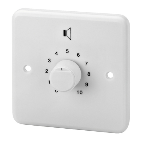
Monacor ATT-212/WS User manual

Monacor

Monacor ATT-212/WS User manual

Monacor ATT-212/WS User manual

Monacor

Monacor ATT-212/WS User manual

Monacor PA-24FMM Quick guide

Monacor

Monacor PA-24FMM Quick guide

Monacor PA-1200IRD User manual

Monacor

Monacor PA-1200IRD User manual

Monacor PA-1200EX User manual

Monacor

Monacor PA-1200EX User manual

Monacor ATT-442ST User manual

Monacor

Monacor ATT-442ST User manual

Monacor VCA-202R User manual

Monacor

Monacor VCA-202R User manual

Monacor PA ATT-235/WS User manual

Monacor

Monacor PA ATT-235/WS User manual

Monacor DN-1 User manual

Monacor

Monacor DN-1 User manual

Monacor ATT-210P/WS User manual

Monacor

Monacor ATT-210P/WS User manual

Monacor TVCCD-38MCOL User manual

Monacor

Monacor TVCCD-38MCOL User manual

Popular Control Unit manuals by other brands

Eaton SystemStak DGM 3 40 Series manual

Eaton

Eaton SystemStak DGM 3 40 Series manual

Teac ER-LXRC1000 Instructions for use

Teac

Teac ER-LXRC1000 Instructions for use

Wegmatt dAISy Mini manual

Wegmatt

Wegmatt dAISy Mini manual

SOLAREG II GENIUS plus Assembly and operation manual

SOLAREG II

SOLAREG II GENIUS plus Assembly and operation manual

Clemco 20951 manual

Clemco

Clemco 20951 manual

Ormazabal ekor.rci General instructions

Ormazabal

Ormazabal ekor.rci General instructions

Reflex Anybus CompactCom Original operating manual

Reflex

Reflex Anybus CompactCom Original operating manual

Panasonic FP0H Series user manual

Panasonic

Panasonic FP0H Series user manual

Keysight Technologies J7211A Operating and service manual

Keysight Technologies

Keysight Technologies J7211A Operating and service manual

RAK WisBlock RAK12004 quick start guide

RAK

RAK WisBlock RAK12004 quick start guide

SITECNA 04 Series Installation, Regulation and Maintenance Instructions

SITECNA

SITECNA 04 Series Installation, Regulation and Maintenance Instructions

Steiel EF117 instruction manual

Steiel

Steiel EF117 instruction manual

Purified Air UV-O 500 Technical and Operations Manual

Purified Air

Purified Air UV-O 500 Technical and Operations Manual

Sentiotec K1 Next Instructions for installation and use

Sentiotec

Sentiotec K1 Next Instructions for installation and use

acorn controls TEMPFLOW TZV Installation, operation and maintenance instructions

acorn controls

acorn controls TEMPFLOW TZV Installation, operation and maintenance instructions

M-system R3-GD1 instruction manual

M-system

M-system R3-GD1 instruction manual

Vimar by-me 01483 quick start guide

Vimar

Vimar by-me 01483 quick start guide

Emerson Vanessa 30000 Series Installation and maintenance instructions

Emerson

Emerson Vanessa 30000 Series Installation and maintenance instructions

manuals.online logo
manuals.online logoBrands
  • About & Mission
  • Contact us
  • Privacy Policy
  • Terms and Conditions

Copyright 2025 Manuals.Online. All Rights Reserved.