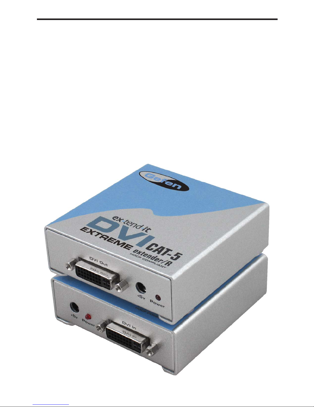
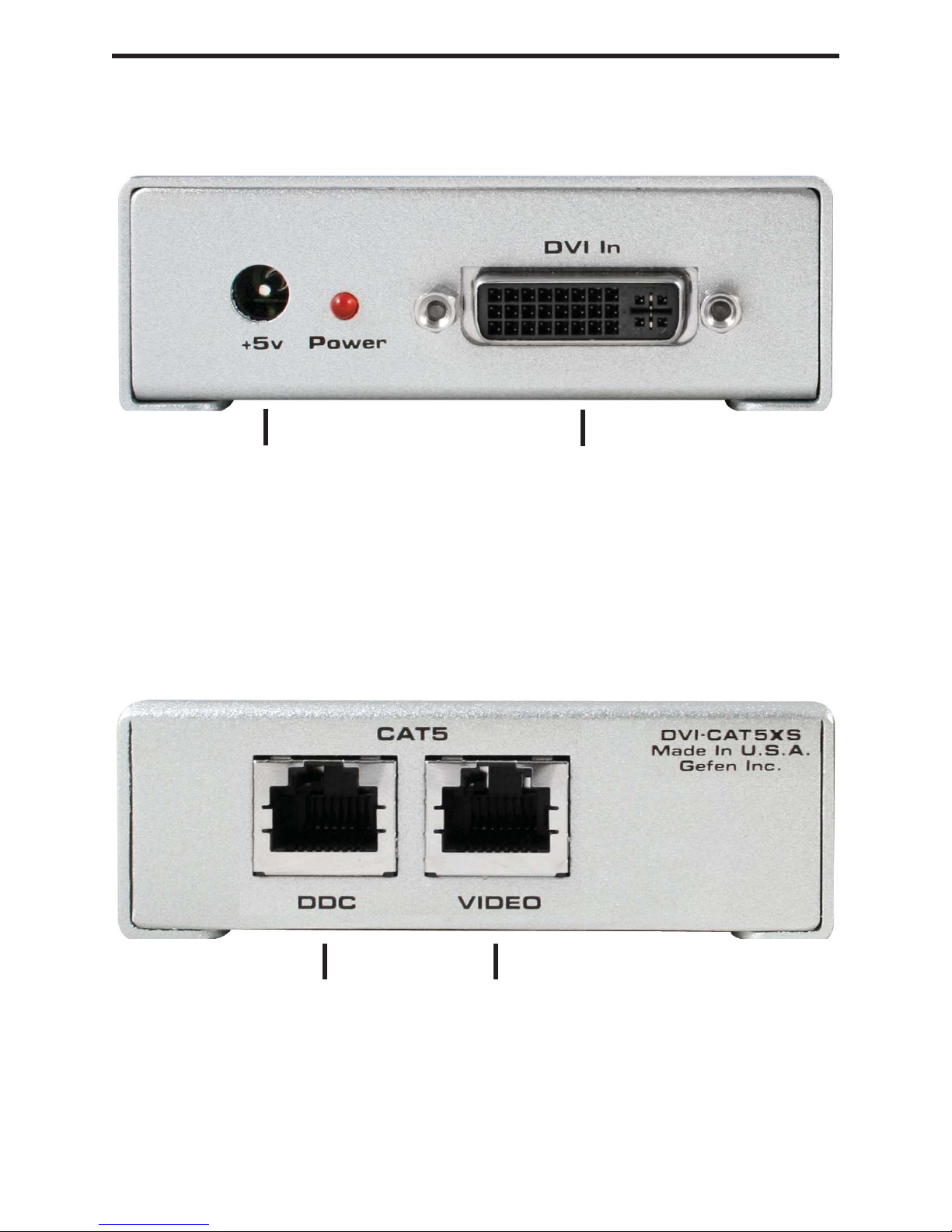
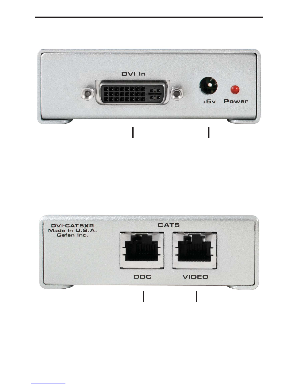
Gefen DVI-CAT5X User manual

DVI CAT-5
Extreme
USER MANUAL
www.gefen.com

Technical Support:
Telephone (818) 772-9100
(800) 545-6900
Fax (818) 772-9120
Technical Support Hours:
8:00 AM to 5:00 PM Monday thru Friday.
Write To:
Gefen Inc.
c/o Customer Service
20600 Nordhoff St.
Chatsworth, CA 91311
www.gefen.com
Notice
Gefen Inc. reserves the right to make changes in the hardware, packaging and any
accompanying documentation without prior written notice.
The DVI CAT-5 Extreme is a trademark of Gefen Inc.
© 2007 Gefen Inc., All Rights Reserved
ASKING FOR ASSISTANCE

TABLE OF CONTENTS
Introduction
DVI CAT-5 Extreme Sender Front Panel Descriptions
DVI CAT-5 Extreme Receiver Front Panel Descriptions
How To Connect The DVI CAT-5 Extreme
Dip Switch Usage Guide
CAT5 Link Cable - Wiring Diagram
Mounting Plate Installation
Frequently Asked Questions
Terminology
Specifications
Warranty
1
2
3
4
5
6
7
8
9
10
11

READ THESE NOTES BEFORE INSTALLING
OR OPERATING THE DVI CAT-5 EXTREME EXTENDER
• The DVI CAT-5 Extreme is housed in a metal box for better RF shielding.
• Your CAT-5 cable should not exceed 200 feet.
• If you do not need DDC data you can use a single CAT-5 cable for the video only. The
DDC will not be connected.
• If the source requires EDID present, you can use the Gefen DVI Detective to provide
EDID information.
* CAT6 cable is suitable for high resolutions at 50 meters.
OPERATION NOTES

INTRODUCTION
The DVI CAT-5 Extreme sender unit sits next to your computer, DVD player or any set-
top box with a DVI output. The cable supplied with the DVI CAT-5 Extreme connects your
DVI source to the send unit. The DVI CAT-5 Extreme receiver unit sits next to your DVI
display - up to 150 feet away. The display plugs into the back of the DVI CAT-5 Extreme
receiver unit. Two CAT-5 cables connect the DVI CAT-5 Extreme-S and the DVI CAT-5
Extreme-R units to each other.
CONTENTS
The DVI CAT-5 Extreme system consists of:
(1) DVI CAT-5 Extreme-S
(1) DVI CAT-5 Extreme-R
(1) 6 ft DVI to DVI Cable M-M
(2) DVI CAT5 Wallmounts
(2) 5V DC power supply
1

DVI CAT-5 EXTREME SENDER FRONT PANEL DESCRIPTIONS
2
DVI input connects to
DVI source
Connects to 5 volt
power supply
CAT-5 carries
TMDS signals
CAT-5 carries
DDC/HDCP signals

DVI CAT-5 EXTREME RECEIVER FRONT PANEL DESCRIPTIONS
3
Connects to DVI display
CAT-5 carries
TMDS signals
CAT-5 carries
DDC/HDCP signals
Connects to 5 volt
power supply

Connect your display to the DVI CAT-5 Extreme receiver unit.
Connect your source to the DVI CAT-5 Extreme sender unit
Connect your CAT-5 cables between the sender and the receiver
Plug the 5V power supply into the DVI CAT-5 Extreme sender and receiver unit
You should now have picture. If you do not see a picture, try unplugging and re-
plugging the DVI input on the DVI sender unit. Make sure your CAT-5 cables are not
crossed. Recycle the power on the unit.
* If problems persist try adjusting the Dip Switches by following the Dip Switch
Usage Guide.
HOW TO CONNECT THE DVI CAT-5 EXTREME
1
2
3
4
5
4

SERVICE SWITCH USAGE GUIDE
5
The Senders and Receivers of the Gefen CAT5 Extreme products both contain a set of
service switches (also called dip switches) located underneath each unit. Peeling back
the silver sticker will reveal the service switch bay. These service switches are used
to boost and equalize the signal to best match the conditions in your setup. (*Note:
Adjustments should be done with sources and display on. Switches 3 and 4 are not
used.)
Sender Dip Switch Settings
Setting Switch 1 Switch 2
No Boost OFF ON
Normal Boost (Default) OFF OFF
Strong Boost ON OFF
Undefined ON ON
Receiver Dip Switch Settings
Setting Switch 1 Switch 2
No EQ (Default) OFF OFF
EQ Setting 2 ON OFF
EQ Setting 3 OFF ON
Maximum EQ ON ON
Adjustment Guidelines:
1) Strong boost should not be used on stranded cables. Strong boosting will cause
pixels or no picture on these cables.
2) Using the wrong settings will not damage the units; it will either produce no
image or a noisy image.
3) To eliminate the possibility of cross talk and interference, cables must be
terminated with 568B scheduling. (See page 6 for details)

CAT5 LINK CABLE - WIRING DIAGRAM
White/Orange
Orange
White/Green
Blue
White/Blue
Green
White/Brown
Brown
RJ-45 Jack RJ-45 Jack
2
3
4
5
6
7
8
1
2
3
4
5
6
7
8
1
1818
6

7
MOUNTING PLATE INSTALLATION

Frequently Asked Questions
What kind of CAT-5e cable should I be using?
Solid core CAT-5e cable rated at 350 Mhz and terminated in 568a or 568b is the
minimum requirement. For resolutions greater than 1280x1024 or 1080i, Gefen
recommends solid CAT-6 cables.
I’m getting no video on the screens, what can I check?
First thing to check is make sure that the video CAT5 is linked to the other video CAT5 port
and the same with the DDC ports. Try removing the power supply from the receiver side,
if the power light turns off then you have your CAT-5 cables crossed. In some setups with
grounding issues you will not get a picture with the receiver powered. Test to make sure
the units are working with short CAT-5e cables 15-20 feet. You can also make sure you
have the correct boost setting configured (refer to page 5).
Occasionally the picture blanks out, how do I fix this?
Flickering or a blinking image is the result of a loss of sync between the display and
the source. Try lowering the resolution to see if that helps, if it does, the CAT-5 cables
you are using are unable to handle the bandwidth of the higher resolution and thus you
are losing sync. Try a shielded CAT-6 cable on the video line to reduce interference.
You can also try adjusting the service switches. Usually this is caused by EMI and
a shielded CAT-6 with metal RJ-45 connectors with the drain wire soldered to the
connectors will resolve the issue. Please refer to the service switch guide on page 5 for
the different combinations.
Why is there a green or pink tint to my picture?
A tint of green or pink in the picture is a result of incorrect colorspace being transmitted.
This can be resolved by recycling power on your devices including the extender. If this
does not help, the DDC data containing the colorspace is not being transmitted correctly
due to loss in the CAT5 cable, try replacing the DDC cable.
TROUBLESHOOTING
8

CAT-5
Category 5 cable, commonly known as Cat 5, is an unshielded twisted pair type cable
designed for high signal integrity. The actual standard defines specific electrical properties
of the wire, but it is most commonly known as being rated for its Ethernet capability of 100
Mbit/s. Its specific standard designation is EIA/TIA-568. Cat 5 cable typically has three
twists per inch of each twisted pair of 24 gauge copper wires within the cable.
CAT-5e
Similar to Cat 5 cable, but is enhanced to support speeds of up to 1000 megabits per
second.
DDC
Short form for Display Data Channel. It is a VESA standard for communication between
a monitor and a video adapter. Using DDC, a monitor can inform the video card about its
properties, such as maximum resolution and color depth. The video card can then use
this information to ensure that the user is presented with valid options for configuring the
display.
DDWG
Digital Display Working Group DDWG are the creators of the DVI specification.
DVI
Digital Visual Interface. Connection standard developed by Intel for connecting computers
to digital monitors such as flat panels and DLP projectors.Aconsumer electronics version,
notnecessarilycompatiblewith thePC version,is usedas aconnection standardfor HDTV
tuners and displays. Transmits an uncompressed digital signal to the display. The latter
version uses HDCP copy protection to prevent unauthorized copying.
HDCP
High-Bandwidth Digital Content Protection. Created by Intel, HDCP is used with HDTV
signals over DVI and HDMI connections and on D-Theater D-VHS recordings to prevent
unauthorized duplication of copy written material.
HDTV
High-DefinitionTelevision.Thehigh-resolutionsubsetof ourDTVsystem.TheATSCdefines
HDTVasa 16:9imagewithtwicethehorizontal andverticalresolutionof ourexistingsystem,
accompanied by 5.1 channels of Dolby Digital audio. The CEAdefines HDTV as an image
with 720 progressive or 1080 interlaced active (top to bottom) scan lines. 1280:720p and
1920:1080i are typically accepted as high-definition scan rates.
VESA
VideoElectronicStandardsAssociation,a consortiumof manufacturersformedtoestablish
andmaintain industrywide standardsforvideocardsand monitors.VESAwas instrumental
in the introduction of the Super VGA and Extended VGA video graphics standards with
a refresh rate of 70 Hz, minimizing flicker and helping to reduce user eyestrain and
fatigue.
TERMINOLOGY
9

Video Amplifier Bandwidth ................................................................................ 1.65 Gbps
Input Video Signal ......................................................................................... 1.2 volts p-p
Input DDC Signal .................................................................................... 5 volts p-p (TTL)
Single Link Range .............................................................................1080p / 1920 x 1200
DVI Connector Type ...................................................... DVI-I 29 pin female (digital only)
Link Connector ........................................................................................................ RJ-45
Power Consumption .................................................................................. 20 watts (max)
Power Supply ......................................................................................................... 5V DC
Dimensions ............................................................................. 3.4” W x 1.25” H x 3.25” D
Shipping Weight ....................................................................................................... 3 lbs.
SPECIFICATIONS
10

Gefen Inc. warrants the equipment it manufactures to be free from defects in material
and workmanship.
If equipment fails because of such defects and Gefen Inc. is notified within two (2) year
from the date of shipment, Gefen Inc. will, at its option, repair or replace the equipment,
provided that the equipment has not been subjected to mechanical, electrical, or other
abuse or modifications.
Equipment that fails under conditions other than those covered will be repaired at the
current price of parts and labor in effect at the time of repair. Such repairs are warranted
for ninety (90) days from the day of reshipment to the Buyer.
This warranty is in lieu of all other warranties expressed or implied, including without
limitation, any implied warranty or merchantability or fitness for any particular purpose, all
of which are expressly disclaimed.
1. Proof of sale may be required in order to claim warranty.
2. Customers outside the US are responsible for shipping charges to and from Gefen.
3. Copper cables are limited to a 30 day warranty and cable must be free from any
scratches, markings, and neatly coiled.
Theinformation inthis manualhas beencarefullycheckedandis believedto beaccurate.
However, GefenInc. assumesnoresponsibilityforany inaccuraciesthat maybe contained
in this manual. In no event will Gefen Inc., be liable for direct, indirect, special, incidental,
or consequential damages resulting from any defect or omission in this manual, even if
advised of the possibility of such damages. The technical information contained herein
regarding the DVI CAT-5 Extreme features and specifications is subject to change without
notice.
WARRANTY
11
Table of contents
Other Gefen Extender manuals

Gefen
Gefen EXT-WRS232 User manual

Gefen
Gefen HDTV-CAT5 User manual

Gefen
Gefen EXT-DVI-FMP User manual

Gefen
Gefen DVI-FM User manual

Gefen
Gefen DVI-1000HD User manual

Gefen
Gefen HDMI CAT-5 User manual

Gefen
Gefen DVI Booster User manual

Gefen
Gefen HDMI CAT-5 IR User manual

Gefen
Gefen DVI-100 User manual

Gefen
Gefen EXT-USB-500 User manual

Gefen
Gefen GTB-HDKVM-ELR User manual

Gefen
Gefen CAT5-5000 User manual

Gefen
Gefen EXT-DVIKVM-ELR User manual

Gefen
Gefen EXT-DIGAUD-141 User manual

Gefen
Gefen EXT-HDKVM-ELR User manual

Gefen
Gefen RS-232 User manual

Gefen
Gefen EXT-DVI-EDIDP User manual

Gefen
Gefen EXT-DVI-1CAT6 User manual

Gefen
Gefen EXT-DVI-CAT5-ELR User manual

Gefen
Gefen DVI-2000HD User manual