manuals.online logo
Brands
  1. Home
  2. •
  3. Brands
  4. •
  5. gefran
  6. •
  7. Controllers
  8. •
  9. gefran GFX4-IR User manual

gefran GFX4-IR User manual

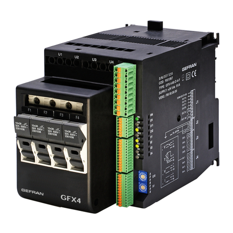
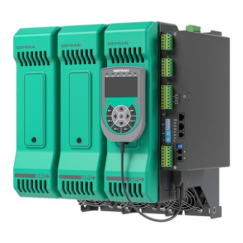
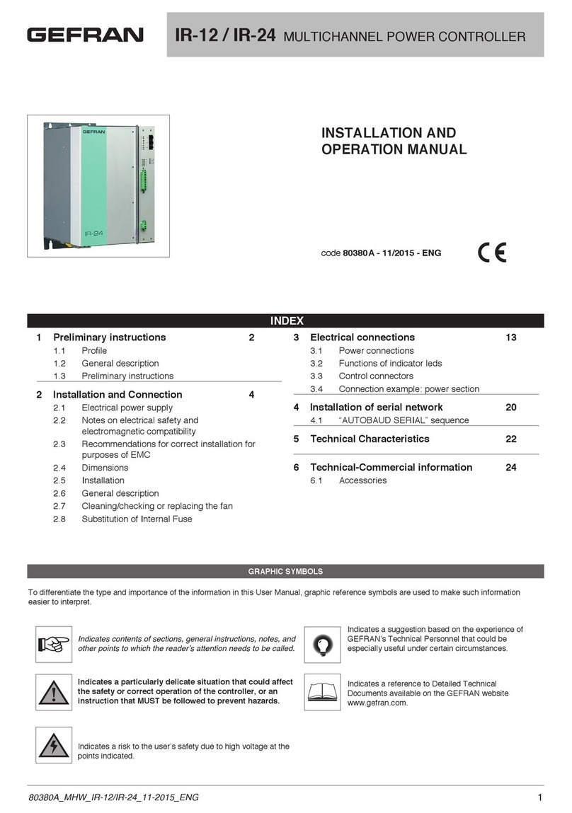
GFX4-IR
4-ZONE MODULAR POWER
CONTROLLER FOR IR LAMPS AND
INDUCTIVE LOADS
INSTALLATION AND OPERATION MANUAL
Side 1 Installation and Connection
Electrical connections
Side 2 Technical-Commercial information
General Information
Dimensions
Fixing/Installation
Derating curves
code 80418B - 12/2015 - ENG
SECTION CABLE
INSTALLATION AND CONNECTION
This section contains the instructions needed for correct installation of GFX4-IR modular power control-
ler on the machine/host system control panel and for correct connection of the power supply, inputs,
outputs and interfaces.
Carefully read the following warnings before installing the instrument!
Disregard of such warnings could create electrical safety and electromagnetic compatibility problems, as
well as void the warranty.
ELECTRICAL POWER SUPPLY
• the product DOES NOT have an On/Off switch: the user must install switch/isolator conforming to safety
requisites (CE mark) to cut off the power supply up-line of the controller.
The switch must be installed in the immediate vicinity of the controller in easy reach of the operator.
A single switch can be used for multiple devices.
* the earth connection must be made with a specific lead
• if the product is used in applications with risk of harm to persons or damage to machines or materials, it
MUST be equipped with auxiliary alarm devices.
It is advisable to provide the ability to check for tripped alarms during regular operation.
NOTES ON ELECTRICAL SAFETY AND ELECTROMAGNETIC COMPATIBILITY:
CE: CONFORMITY EMC (ELECTROMAGNETIC COMPATIBILITY) CONFORMITY)
in compliance with Directive 2004/108/CE and following modifications. Series GFX4-IR are mainly intended
for industrial use, installed on panels or control panels of production process machines or systems. For pur-
poses of electromagnetic compatibility, the most restrictive generic standards have been adopted, as shown
on the table.
LV (low voltage) conformity) in compliance with Directive 2006/95/CE.
EMC conformity has been verified with the connections indicated on table 1 (see user’s manual).
ATTENTION
This product has been designed for class A equipment. Use of the product in domestic environments may
cause radio interference, in which case the user may be required to employ additional mitigation methods.
RECOMMENDATIONS FOR CORRECT INSTALLATION FOR PURPOSES OF EMC
Instrument power supply
• The power supply for the electronic instrumentation on the panels must always come directly from a cut-off
device with fuse for the instrument part.
• Electronic instrumentation and electromechanical power devices such as relays, contactors, solenoids,etc.,
MUST ALWAYS be powered by separate lines.
• When the power supply line of electronic instruments is heavily disturbed by switching of thyristor power
groups or by motors, you should use an isolation transformer only for the controllers, grounding its sheathing.
• It is important for the system to be well-grounded:
- voltage between neutral and ground must not be > 1V
- Ohmic resistance must be < 6Ω;
• If the grid voltage is highly unstable, use a voltage stabilizer.
• In proximity of high-frequency generators or arc welders, use adequate grid filters.
• The power supply lines must be separate from instrument input and output lines.
• Supply from Class II or from limited energy source
Input and output connections
Before connecting or disconnecting any connection, always check that the power and control cables are iso-
lated from voltage.
Appropriate devices must be provided: fuses or automatic switches to protect power lines.
The fuses present in the module function solely as a protection for the GFX4-IR semiconductors.
• Connected outside circuits must be doubly isolated.
• To connect analog inputs, strain gauges, linears, (TC, RTD), you have to:
- physically separate the input cables from those of the power supply, outputs, and power connections.
- use braided and shielded cables, with sheathing grounded at a single point.
• To connect the control outputs and alarm outputs (contactors, solenoids, motors, fans, etc.), install RC
(series of capacitors and resistors) groups parallel to inductive loads that work in AC.
(Note: all condensers must conform to VDE standards (class X2) and support voltage of at least 220Vac.
Resistances must be at least 2W).
• Install a 1N4007 diode anti-parallel to the coil of inductive loads that work in DC.
GEFRAN S.p.A. assumes no liability for any damage to persons or property deriving from tampering,
from incorrect or improper use, or from any use not conforming to the characteristics of the controller
and to the instructions in this User Manual.
ConneCtions
GEFRAN spa
via Sebina, 74 - 25050 Provaglio d’Iseo (BS)
Tel. 03098881 - fax 0309839063- Internet: http://www.gefran.com
ELECTRICAL CONNECTIONS
0,2 - 6mm224-10AWG
Model
max current
80kW
57A (40A)*
0,5 - 16mm220-6AWG
0,2 - 4mm224-10AWG 0,5 - 10mm220-7AWG
0,25 - 4mm223-10AWG 0,5 - 10mm220-7AWG
0,5 - 0,6Nm 1,2 - 1,5Nm
rigid
flexible
30kW
16A
60kW
32A (30A)*
* UL certification
Power ConneCtions
Model without fuse holder
F1,F2,F3,F4/N Line connection terminals
U1,U2,U3,U4 Load connection terminals
F1,F2,F3,F4/N Line connection terminals
U1,U2,U3,U4 Load connection terminals
Model with fuse holder
N
L1
Load 1
Load 2
Load 3
Load 4
+
+
+
+
_c (OUT 5,...8)
(OUT 5 no)
OUT 9
(OUT 6 no)
(OUT 7 no)
(OUT 8 no)
OUT 10
c
c
no
no
+
+
+
+
_
POWER SUPPLY
18...32Vdc
+24Vdc
OUT 1
OUT 2
OUT 3
OUT 4
IN 5
IN 6
IN 7
IN 8
IN 1
IN 2
IN 3
IN 4
C1
O5
O6
O7
O8
C9
O9
C10
O10
O1
O2
O3
O4
O2
O3
O4
J3a
RN
J1a
ER
DI2
DI1
J1
J2
J3
J4
1
9
1
7
1
12
1
12
DI2
DI1
M
M
L+
L+
O1
I5-
I5+
I6-
I6+
I7-
I7+
I8-
I8+
I1-
I1+
IN1
I2-
I2+
IN2
I3-
I3+
IN3
I4-
I4+
IN4
Triac Logica/continua Relè
Port 1
Port 2
S1
S2
S3
S4
S5
4
3
2
1
4
3
2
1
+VI
Tx/Rx-
Tx/Rx+
GNDI
+VI
Tx/Rx-
Tx/Rx+
GNDI
6
9
1
4
Triac Logic/continuous Relay
Conformity TC N° RUД-IT.AЛ32.b.01762
CSA Conformity C/CSA/US CoFC no. 70043834
UL Conformity C/UL/US File no. E243386
This device conforms to European Union Directive 2004/108/CE e 2006/95/CE with reference to generic standards:
EN 60947-4-3 (product) EN 61010-1 (safety)
Graphic simbol
Indicates contents of sections, general instructions, notes, and other points to which the reader’s attention needs
to be called.
Indicates a particularly delicate situation that could affect the safety or correct operation of the controller, or an
instruction that MUST be followed to prevent hazards.
Indicates a risk to the user’s safety due to high voltage at the points indicated.
DIMENSIONS
TECHNICAL CHARACTERISTICS / GENERAL DATA FIXING / INSTALLATION
GENERAL DATA
Power supply 24Vdc ±25%, Class II, max 8VA
Fan power supply 24Vdc ±10%, 500mA @ 25Vdc
Signals Eight LEDs:
RN run state of CPU ER error signal
DI1, DI2, state of digital inputs O1...O4 state of SCR control
Protection IP20
Work/storage temperature 0…50°C (refer to dissipation curves) / -20 °C - +70 °C
Relative humidity 20…85% RH non-condensing
Ambient conditions for use indoor use, altitude up to 2000m
Installation DIN bar EN50022 or panel with screws
Installation requirements Installation category II, pollution level 2, double isolation
Max. temperature of air surrounding device 50°C Device type: “UL Open Type”
Weight Models 30KW, 60KW, 80KW
Models 30KW, 60KW with fuses
1200 g.
1600 g.
External EMC filters
The need to use a filter to obtain emissions conducted on the line during power-on of SCRs with phase angle trigger depends on
the applications.
It is important to connect the power filter as close as possible to the solid-state power unit.
We recommend a filter with the following characteristics:
Voltage Load voltage
Current Max. current on load
Rated frequency 50/60Hz
Common mode attenuation >35dB@100KHz >60dB from 150KHz to 1.5MHz
Differential mode attenuation >50dB@100KHz >60dB from 150KHz to 1.5MHz
The following are two commercial filters tested in single-phase applications:
Model Load 230V Load 400V
GFX4-IR 30KW ICAR FL140.30.00 ICAR FL140.30.00 H
GFX4-IR 60-80KW ICAR FL140.50.00 ICAR FL140.50.00 H
The CE declaration of conformity is available on request.
Model without fuse holder
Model with fuse holder
Attention: respect the minimum distances shown in figure to provide adequate
air circulation.
- Panel mounting and cut-out dimensions
- Installation
Model
EXTRARAPID FUSES FUSES-HOLDER
ISOLATORS
Size
I²t
Code
Format
Model
Code
Power
Dissipated @ In
Approval
Code
GFX4-IR 30 kw 16A
150 A²s
FUS-016
10x38
FWC16A10F
338470 3,5 W PFI-10x38
337134 UR30A@690V
GFX4-IR 60 kw 30A
675 A²s
FUS-030
10x38
FR10GR69V30
338481 4,8 W PFI-10x38
337134 UR30A@690V
GFX4-IR 80 kw 63A
3080 A²s
FUS-063
22x58
FWP63A22F
338191 11 W PFI-22x88
337223 UR80A@600V
POWER (SOLID-STATE RELAY)
Load type AC 51 resistive or low inductance loads
AC 55b short wave infrared lamps (SWIR)
AC 56a transformers, resistive loads with high temperature coefcient
Trigger mode PA - load control via adjustment of ring phase angle
ZC - Zero Crossing with constant cycle time (settable in range 1-200sec)
BF - Burst Firing with variable cycle time (GTT) optimized minimum.
HSC - Half Single Cycle corresponds to Burst Firing that includes ON and OFF half-cycles.
Useful for reducing icker with short-wave IR loads (applied only to single-phase resistive or
3-phase 6-wire open delta loads).
Feedback mode V: Voltage feedback: proportional to RMS voltage value on load to compensate possible
variations in line voltage.
I: Current feedback: proportional to RMS current value on load to compensate variations in
line voltage and/or variations in load impedance.
W: Power feedback: proportional to real power value on load to compensate variations
in line voltage and/or variations in load impedance. You have to calibrate each time you
change feedback mode.
Max rated voltage 480Vac
Work voltage range 90…530Vac
Non-repetitive voltage 1200Vp
Rated frequency 50/60Hz auto-determination
Rated current AC51 non-
inductive or slightly inductive
loads, resistance furnaces
30KW
4x16A
60KW
4x32A (4x30)*
80KW
4x40A (4x40)*
(single channel 57A ∑I= 160A)
Nominal current AC55b
short wave infrared lamps
30KW
4x8A
60KW
4x16A
80KW
4x20A
for applications in which you can set a minimum power output limit (ex: Lo.P = 10%) by also
limiting the lamp power variation speed with gradient limit (ex: G.out = 20%, PS.TM = 20s).
Under these conditions, the nominal currents shown on the table can be raised up to the
values indicated for AC51 type loads.
Rated current AC56A load tran-
sfomar permitted trigger modes:
ZC, BF with DT (Delay Triggering),
PA with sofstart
30KW
4x12A
60KW
4x25A
80KW
4x32A
Non-repetitive overcurrent
(t=20msec) 400A 600A 1150A
I2t for melting (t=1…10msec) 645A2s 1010A2s 6600A2s
Critical Dv/dt with output
deactivated 10,000V/ms High static dv/dt
Rated isolation voltage 4000V
* UL Certification
Current [A]
Ambient temperature [°C]
DERATING
45
40
35
30
25
20
15
10
5
00 10 20 30 40 50 60
GFX4-IR-80
GFX4-IR-60
GFX4-IR-30
DERATING CURVES

Other manuals for GFX4-IR

2

This manual suits for next models

1

Other gefran Controllers manuals

gefran eView BOX User manual

gefran

gefran eView BOX User manual

gefran GFW 40-300A User manual

gefran

gefran GFW 40-300A User manual

gefran SIEIDrive LIFT AGy -L User manual

gefran

gefran SIEIDrive LIFT AGy -L User manual

gefran GFW-Xtra User manual

gefran

gefran GFW-Xtra User manual

gefran AGL50-EV Series User manual

gefran

gefran AGL50-EV Series User manual

gefran 1000 User manual

gefran

gefran 1000 User manual

gefran 1600P User manual

gefran

gefran 1600P User manual

gefran ADV200 Series User manual

gefran

gefran ADV200 Series User manual

gefran GTF Series User manual

gefran

gefran GTF Series User manual

gefran GF_LOOPER 3.5” User manual

gefran

gefran GF_LOOPER 3.5” User manual

gefran ADV200 Series Parts list manual

gefran

gefran ADV200 Series Parts list manual

gefran GEFLEX Multifunction Product manual

gefran

gefran GEFLEX Multifunction Product manual

gefran GFW-Xtra 40 User manual

gefran

gefran GFW-Xtra 40 User manual

gefran Zapper User manual

gefran

gefran Zapper User manual

gefran 600 User manual

gefran

gefran 600 User manual

gefran 40T 72 PID User manual

gefran

gefran 40T 72 PID User manual

gefran GFW ADV Instruction sheet

gefran

gefran GFW ADV Instruction sheet

gefran AGy -L User manual

gefran

gefran AGy -L User manual

gefran 800P User manual

gefran

gefran 800P User manual

gefran 1300 User manual

gefran

gefran 1300 User manual

gefran GFX4 User manual

gefran

gefran GFX4 User manual

gefran GSLM User manual

gefran

gefran GSLM User manual

gefran IR-12 Owner's manual

gefran

gefran IR-12 Owner's manual

gefran 1200 Owner's manual

gefran

gefran 1200 Owner's manual

Popular Controllers manuals by other brands

AirCom R102 operating manual

AirCom

AirCom R102 operating manual

Siemens OpenAir GDE141.1U Technical instructions

Siemens

Siemens OpenAir GDE141.1U Technical instructions

Allen-Bradley powerflex 700 Technical data

Allen-Bradley

Allen-Bradley powerflex 700 Technical data

National Instruments PXI-8115 installation guide

National Instruments

National Instruments PXI-8115 installation guide

Solcon RVS-DN instruction manual

Solcon

Solcon RVS-DN instruction manual

Oase InScenio FM-Master Series operating instructions

Oase

Oase InScenio FM-Master Series operating instructions

NHT PVC-PC user guide

NHT

NHT PVC-PC user guide

Johnson Controls M9204-B 2Z Series installation guide

Johnson Controls

Johnson Controls M9204-B 2Z Series installation guide

Jamara CR40EP Instruction

Jamara

Jamara CR40EP Instruction

Clarke Air CAT865 Operating & maintenance instructions

Clarke

Clarke Air CAT865 Operating & maintenance instructions

Sierra Wireless AirPrime SL8084T Integration guide

Sierra Wireless

Sierra Wireless AirPrime SL8084T Integration guide

Yamatake azbil FRS100 user manual

Yamatake

Yamatake azbil FRS100 user manual

AirTek NFT28U quick start guide

AirTek

AirTek NFT28U quick start guide

THORLABS K-Cube Piezo Controller user guide

THORLABS

THORLABS K-Cube Piezo Controller user guide

maxon motor EPOS2 70/10 Hardware reference

maxon motor

maxon motor EPOS2 70/10 Hardware reference

Emerson Fisher LR125 Series instruction manual

Emerson

Emerson Fisher LR125 Series instruction manual

zeeltronic VCDI-04 user manual

zeeltronic

zeeltronic VCDI-04 user manual

Greenheck MP-100A installation instructions

Greenheck

Greenheck MP-100A installation instructions

manuals.online logo
manuals.online logoBrands
  • About & Mission
  • Contact us
  • Privacy Policy
  • Terms and Conditions

Copyright 2025 Manuals.Online. All Rights Reserved.