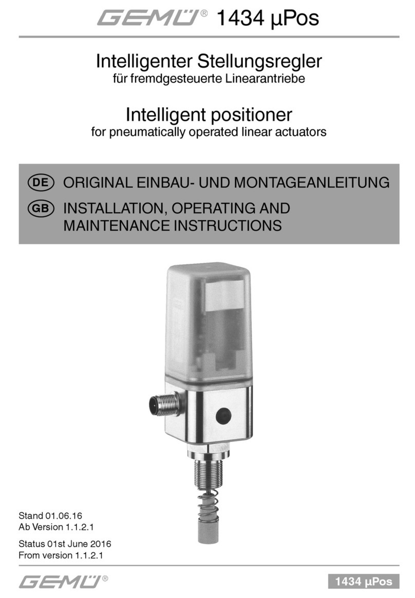
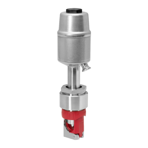
GEM 1436 cPos User manual

1436 cPos eco
1436 cPos eco
Intelligenter Stellungsregler
für fremdgesteuerte Linearantriebe
ORIGINAL QUICK GUIDE
DE
Stand 01.06.16
Intelligent Positioner
for pneumatically operated linear actuators
QUICK GUIDE
GB
Status 01st June 2016

1436 cPos eco 2 / 20
Inhaltsverzeichnis
1 Sicherheitshinweise 2
2 Mechanischer Anbau 2
2.1 Anbau an Linearantriebe 2
2.1.1 Vorbereitung des Ventilantriebes 2
2.1.2 Komplettierung des Weggebers 2
2.1.3 Anbau des Stellungsreglers 3
2.1.4 Anbau des externen Weggebers
(nur bei Variante mit externem
Anbau) 3
2.2 Anbau an Schwenkantriebe 4
2.2.1 Vorbereitung des Ventilantriebes 4
2.2.2 Komplettierung des Weggebers 4
2.2.3 Anbau des Stellungsreglers 5
2.2.4 Anbau des externen Weggebers
(nur bei Variante mit externem
Anbau) 5
3 Pneumatische Anschlüsse 6
4 Elektrische Anschlüsse 6
4.1 Variante mit externem Weggeber
(Code S01) 7
5 Initialisierung und
Inbetriebnahme 7
5.1 Elektrischer und pneumatischer
Anschluss 7
5.2 Automatische Initialisierung 8
5.3 Inbetriebnahme 9
6 Hinweise 9
1 Hinweise zur Sicherheit
Die Sicherheitshinweise entnehmen Sie
bitte der Bedienungsanleitung des GEMÜ
1436 cPos eco.
Sollten Sie nicht im Besitz dieser
Bedienungsanleitung sein, wenden Sie sich
bitte an GEMÜ.
2 Mechanischer Anbau
2.1 Anbau an Linearantriebe
2.1.1 Vorbereitung des Ventilantriebes
lAntrieb muss sich in Grundstellung
(Antrieb entlüftet) befinden.
lBefindet sich im Antrieb oben eine
optische Sichtanzeige (rote Spindel), so
ist diese herauszuziehen.
2.1.2 Komplettierung des Weggebers
GEFAHR
Vorgespannte Feder!
äBeschädigung des Gerätes.
● Feder langsam entspannen.
Achtung: Eine Beschädigung
der Spindeloberfläche kann zum
Ausfall des Weggebers führen!
Der Weggeber wird mit einem Anbausatz
1436S01Z... (direkter Anbau) bzw.
4232S01Z... (externer Anbau), bestehend
aus Druckfeder, Betätigungsspindel und
evtl. Gewindeadapter komplettiert. Der
Anbausatz ist ventilspezifisch.
Weggeber
Spindel Druckfeder
Betätigungsspindel
Anbausatz
1. Spindel aus Weggeber bis Anschlag
herausziehen.
2. Druckfeder über Spindel schieben.
3. Spindel an Punkt afixieren
(Spindel darf dabei nicht beschädigt
werden).
a
4. Betätigungsspindel auf Spindel
aufschrauben.

1436 cPos eco
3 / 20
2.1.3 Anbau des Stellungsreglers
1
2
3
Ventil mit Stellungsregler
● Weggeber komplettieren (siehe Kapitel
2.1.2 „Komplettierung des Weggebers“).
lStellungsregler 1auf Antrieb 3
aufsetzen und mit einem geeigneten
Gabelschlüssel SW27 am Weggeber 2
fixieren.
Der Regler darf nicht durch
drehen des Gehäuses befestigt
werden, da sonst die Gefahr
besteht, dass der interne
Anschlag überdreht wird.
Der Stellungsregler lässt sich nach
korrektem Anbau auf das entsprechende
Ventil ausrichten.
eco
OPEN
ERROR
CLOSED
POWER
SW27
1
3
2
eco
OPEN
ERROR
CLOSED
POWER
Stellungsregler und
Antrieb
Stellungsregler auf
Antrieb montiert
2.1.4 Anbau des externen Weggebers
(nur bei Variante mit externem
Anbau)
)
4
3
1
Ventil mit externem Weggeber
● Stellungsregler 1an geeigneter Stelle
befestigen.
Hierzu kann der Befestigungs-
winkel GEMÜ 1446 00 ZMP
verwendet werden (dieser
muss separat bestellt werden).
● Weggeber komplettieren (siehe Kapitel
2.1.2 „Komplettierung des Weggebers“).
lWeggeber 4auf Antrieb 3aufsetzen und
mit einem geeigneten Gabelschlüssel
SW27 am Weggeber 4fixieren.
SW27
3
4
Weggeber und Antrieb
Weggeber auf Antrieb montiert

1436 cPos eco 4 / 20
2.2 Anbau an Schwenkantriebe
2.2.1 Vorbereitung des Ventilantriebes
5
0° / ZU
90° / AUF
● Antrieb muss sich in Grundstellung
(Antrieb entlüftet) befinden.
● Schraube 5zur Befestigung der
optischen Sichtanzeige entfernen.
● Drehrichtung des Antriebes ermitteln (Die
Drehrichtung des Antriebes muss, von
oben betrachtet, gegen den Uhrzeigersinn
sein, wenn der Antrieb von der Stellung
ZU in die Stellung AUF fährt).
2.2.2 Komplettierung des Weggebers
● Vor der Montage an den Antrieb ist darauf
zu achten, dass die Wellenhöhe und das
Lochbild des Antriebs mit den Maßen des
Haltewinkels 6übereinstimmen.
90°
45°0°
6
Ansicht X mit Haltewinkel und Adapter
● Die Welle des Weggebers ist mit einer
Markierung 7versehen. Stimmt diese
Markierung mit der Markierung auf der
Unterseite des Weggebergehäuses 8
überein, so befindet sich der Weggeber in
der 0° Stellung.
7
Weggeber mit Markierung
8
Ansicht X nur Weggeber
● Der elektrische Drehbereich befindet sich
90° im Uhrzeigersinn von dieser Stellung.
● Adapter 9auf Welle des Weggebers 7
setzen.
7
9
● Stellungsregler 1bzw. Weggeber 4auf
Haltewinkel 6schrauben
eco
OPEN
ERROR
CLOSED
POWER
9
6
1
Ansicht X
9
6
4

1436 cPos eco
5 / 20
2.2.3 Anbau des Stellungsreglers
1
2
9
3
6
Ventil mit Stellungsregler
● Weggeber komplettieren (siehe Kapitel
2.2.2 „Komplettierung des Weggebers“).
● Stellungsregler 1mit Adapter 9und
Haltewinkel 6auf Antrieb 3aufsetzen.
Nase von Adapter 9muss
in Nut von Antriebswelle
einrasten.
eco
OPEN
ERROR
CLOSED
POWER
9
6
3
1
● Haltewinkel 6mit beiliegenden
Schrauben auf Antrieb 3befestigen.
eco
OPEN
ERROR
CLOSED
POWER
9
6
3
1
2.2.4 Anbau des externen Weggebers
(nur bei Variante mit externem
Anbau)
4
9
6
3
Ventil mit externem Weggeber
● Stellungsregler 1an geeigneter Stelle
befestigen.
Hierzu kann der Befestigungs-
winkel GEMÜ 1446 00 ZMP
verwendet werden (dieser
muss separat bestellt werden).
● Weggeber komplettieren (siehe Kapitel
2.2.2 „Komplettierung des Weggebers“).
● Weggeber 4mit Adapter 9und
Haltewinkel 6auf Antrieb 3aufsetzen.
Nase von Adapter 9muss
in Nut von Antriebswelle
einrasten.
6
4
3
9
lHaltewinkel 6mit beiliegenden
Schrauben auf Antrieb 3befestigen.
6
3
4

1436 cPos eco 6 / 20
3 Pneumatische Anschlüsse
Achtung: max. Steuerdruck des
Antriebs beachten!
Pneumatische Anschlüsse
Anschluss DIN ISO
1219-1 Bezeichnung Größe
P 1 Versorgungsluftan-
schluss G 1/8
R 3 Entlüftungsanschluss
mit Schalldämpfer G 1/8
V1 V1 Zuluft-Drossel für A1
(Anschluss 2) -
V2 V2 Abluft-Drossel für A1
(Anschluss 2) -
V5 V5 Rückschlagventil -
A1 2
Arbeitsanschluss für
Prozessventil (Steuer-
funktion 1 und 2)
G 1/8
4 Elektrische Anschlüsse
Kabelbruchgefahr!
– Elektrische
Anschlüsse um
maximal 360°
verdrehen.
45
12
3
max. 360°
Um ein sicheres Wiederanlaufen
des Reglers nach einer Unter-
brechung der Versorgungs-
spannung zu gewährleisten,
muss die Versorgungsspannung
länger als 3 Sekunden unterbro-
chen werden.
X1
1
4
3
2
5
X1
Elektrische Anschlüsse
Anschluss Pin Signalname
X1
M12-Stecker
A-Kodierung
1 Uv, 24 V DC Versorgungsspannung
2 I+, 4...20 mA Sollwerteingang
3 Uv, I-, GND
4 I+, 4...20 mA Stellungsrückmeldung
5
Uv, Initialisierung 24 V DC,
Auslösung der Initialisierung
mittels Impulssignal

1436 cPos eco
7 / 20
4.1 Variante mit externem
Weggeber (Code S01)
X4
15
4
3
2
X4
Anschluss Pin Signalname
X4
M12-Buchse
A-Kodierung
1UP+, Ausgang Potentiometer
Versorgungsspannung (+)
2UP, Eingang Potentiometer-
schleiferspannung
3UP-, Ausgang Potentiometer
Versorgungsspannung (-)
4 n.c.
5 n.c.
5 Initialisierung und
Inbetriebnahme
Wird der GEMÜ 1436 cPos eco
ab Werk komplett an ein Ventil
montiert geliefert, so ist dieser
schon werkseitig voreingestellt
(bei einem Steuerdruck von
5,5 - 6 bar ohne Betriebsdruck)
und somit betriebsbereit.
Eine Neuinitialisierung (siehe
Kapitel 5.2) wird empfohlen,
wenn die Anlage mit einem
abweichenden Steuerdruck
betrieben wird oder es eine
Veränderung der mechanischen
Endlagen gegeben hat (z. B.
Dichtungswechsel am Ventil oder
Antriebsaustausch).
Die Initialisierung bleibt auch bei
einer Spannungsunterbrechung
erhalten.
5.1 Elektrischer und
pneumatischer Anschluss
Bedeutung der Symbole siehe
Betriebsanleitung Kapitel
"Anzeigeelemente".
1. Verbindung zwischen pneumatischem
Stellungsreglerausgang A1
(einfachwirkend) und pneumatischem
Steuerlufteingang des Antriebes
herstellen.
2. Hilfsenergie (Zuluft) an Versorgungsluft-
anschluss Panschließen (max. 7 bar)
(siehe Kapitel 3 "Pneumatische
Anschlüsse").
3. Versorgungsspannung 24 V einschalten
(siehe Kapitel 4 "Elektrische Anschlüsse").
LED Symbol LED Symbol
OPEN ICLOSED I
ERROR bPOWER l
GND
+24V DC 4 3
1 2
5

1436 cPos eco 8 / 20
4. Externen Weggeber 4mit
Stellungsregler 1verbinden (nur bei
Variante mit externem Anbau).
4
1
Externer Anbau an Linearantrieb
Externer Anbau an Schwenkantrieb
4
1
5.2 Automatische Initialisierung
Bei sehr kleinen Antriebsvolumen
ist es evtl. notwendig die internen
Drosseln (V1 undV2) des Reglers
ein wenig zu schließen, um die
Ventilstellzeiten zu vergrößern.
Anschließend muss die
Initialisierung neu gestartet werden.
Ventilstellzeiten von ca.
1-2 Sekunden führen
erfahrungsgemäß zu optimalen
Regelergebnissen.
Bedeutung der Symbole siehe
Betriebsanleitung Kapitel
"Anzeigeelemente".
1. Initialisierungsspannung 24 V DC an Pin 5
anschließen und aktivieren (t > 100 ms).
LED Symbol LED Symbol
OPEN ICLOSED I
ERROR bPOWER l
GND
+24V DC 4 3
1 2
5
2. Initialisierungsspannung deaktivieren.
LED Symbol LED Symbol
OPEN ICLOSED I
ERROR mPOWER l
GND
+24V DC 4 3
1 2
5

1436 cPos eco
9 / 20
äDie automatische Initialisierung wird
durchgeführt.
LED Symbol LED Symbol
OPEN ICLOSED I
ERROR mPOWER l
Initialisierung
5.3 Inbetriebnahme
GEFAHR
Lärmentwicklung durch Abluft
und Schaltwechsel!
äGehörschäden.
lGehörschutz tragen.
Bedeutung der Symbole siehe
Betriebsanleitung Kapitel
"Anzeigeelemente".
lAnalogen Sollwert 4-20 mA vorgeben.
LED Symbol LED Symbol
OPEN mCLOSED m
ERROR mPOWER l
GND
4 3
1 2
5+4-20mA
äNach Beenden der Initialisierung wird
das Prozessventil in die Position gemäß
Sollwertsignal positioniert.
Sollwert min
LED Symbol LED Symbol
OPEN mCLOSED l
ERROR mPOWER l
Sollwert max
LED Symbol LED Symbol
OPEN lCLOSED m
ERROR mPOWER l
6 Hinweise
Hinweis:
Handhabung, Montage und
Inbetriebnahme, sowie Einstell-
und Justierarbeiten, dürfen nur
von autorisiertem Fachpersonal
durchgeführt werden. Für
Schäden, welche durch
unsachgemäße Handhabung
oder Fremdeinwirkung
entstehen, übernimmt GEMÜ
keinerlei Haftung. Nehmen
Sie im Zweifelsfall vor
Inbetriebnahme Kontakt mit
GEMÜ auf.
Hinweis zur Mitarbeiterschu-
lung:
Zur Mitarbeiterschulung nehmen
Sie bitte über die Adresse auf
der letzten Seite Kontakt auf.
Im Zweifelsfall oder bei Missverständnissen
ist die deutsche Version des Dokuments
ausschlaggebend!

1436 cPos eco 10 / 20
Contents
1 Safety notes 10
2 Mechanical mounting 10
2.1 Mounting to linear actuators 10
2.1.1 Preparation of the valve actuator 10
2.1.2 Assembling the travel sensor 10
2.1.3 Mounting the positioner 11
2.1.4 Mounting the external travel
sensor (only for version with
remote mounting) 11
2.2 Mounting to quarter turn actuators 12
2.2.1 Preparation of the valve actuator 12
2.2.2 Assembling the travel sensor 12
2.2.3 Mounting the positioner 13
2.2.4 Mounting the external travel
sensor (only for version with
remote mounting) 13
3 Pneumatic connections 14
4 Electrical connections 14
4.1 Version with external actual value
potentiometer (code S01) 15
5 Initialisation and commissioning 15
5.1 Electrical and pneumatic
connection 15
5.2 Automatic initialisation 16
5.3 Commissioning 17
6 Information 17
1 Safety notes
Please refer to the safety notes included
in the GEMÜ 1436 cPos eco operating
instructions.
If you do not have this operating instructions,
please contact GEMÜ.
2 Mechanical mounting
2.1 Mounting to linear actuators
2.1.1 Preparation of the valve actuator
lThe actuator must be in the zero position
(actuator vented).
lShould there be an optical position
indicator in the actuator (a red spindle), it
must be removed.
2.1.2 Assembling the travel sensor
DANGER
Pretensioned spring!
äDamage to the device.
● Slowly relax spring.
Attention:Damage to the spindle
surface may lead to failure of the
travel sensor!
The travel sensor is assembled using a
mounting kit 1436S01Z... (direct mounting)
or 4232S01Z... (remote mounting)
consisting of a spring, an operating bush
and a threaded adapter (if applicable). The
mounting kit depends on the valve type.
Travel sensor
Spindle Compression spring
Operating bush
Mounting kit
1. Pull out the spindle of the travel sensor up
to the limit stop.
2. Push the spring over the spindle.
3. Fix the spindle at point a
(the spindle must not be damaged
during this process).
a
4. Screw the operating bush onto the
spindle.

1436 cPos eco
11 / 20
2.1.3 Mounting the positioner
1
2
3
Valve with positioner
● Assemble the travel sensor (see chapter
2.1.2 “Assembling of the travel sensor”).
lMount the positioner 1by screwing the
travel sensor hexagonal nut SW27 2into
the actuator 3.
The positioner must not be
fixed by turning the housing as
this may result in the danger of
overturning the internal stop.
If correctly mounted to the valve, the
positioner can be aligned.
eco
OPEN
ERROR
CLOSED
POWER
SW27
1
3
2
eco
OPEN
ERROR
CLOSED
POWER
Positioner and
actuator
Positioner mounted to
the actuator
2.1.4 Mounting the external travel
sensor (only for version with
remote mounting)
g)
4
3
1
Valve with external travel sensor
● Fix the positioner 1at a suitable location.
The mounting bracket GEMÜ
1446 00 ZMP can be used
for this purpose (it must be
ordered separately).
● Assemble the travel sensor (see chapter
2.1.2 “Assembling the travel sensor”).
lMount the travel sensor 4by screwing the
travel sensor hexagonal nut SW27 4into
the actuator 3.
SW27
3
4
Travel sensor and actuator
Travel sensor mounted to the actuator

1436 cPos eco 12 / 20
2.2 Mounting to quarter turn
actuators
2.2.1 Preparation of the valve actuator
5
0° / CLOSED
90° / OPEN
● The actuator must be in the zero position
(actuator vented).
● Remove the screw 5which retains the
optical position indicator.
● Determine the turn direction of the actuator
(seen from above the turn direction of the
actuator must be anticlockwise, when the
actuator moves from the „CLOSED“ to the
„OPEN“ position).
2.2.2 Assembling the travel sensor
● Before mounting the travel sensor to the
actuator, make sure that the shaft height
and the hole pattern in the actuator match
the dimensions of the mounting bracket 6.
90°
45°0°
6
View X with mounting bracket and adapter
● The travel sensor shaft 7is marked. If this
marking corresponds with the marking at
the bottom of the travel sensor housing 8,
the travel sensor is in the 0° position.
7
Travel sensor with marking
8
View X only travel sensor
● The electrical turn range is 90° clockwise
of this position.
● Place the adapter 9on the shaft of the
travel sensor 7.
7
9
● Screw the positioner 1or the travel
sensor 4onto the mounting bracket 6.
eco
OPEN
ERROR
CLOSED
POWER
9
6
1
View X
9
6
4

1436 cPos eco
13 / 20
2.2.3 Mounting the positioner
1
2
9
3
6
Valve with positioner
● Assemble the travel sensor (see chapter
2.2.2 “Assembling the travel sensor”).
● Place the positioner 1with the adapter 9
and mounting bracket 6onto the actuator 3.
The adapter lug 9must
engage in the actuator shaft
groove.
eco
OPEN
ERROR
CLOSED
POWER
9
6
3
1
● Attach the mounting bracket 6to the
actuator 3with the enclosed screws.
eco
OPEN
ERROR
CLOSED
POWER
9
6
3
1
2.2.4 Mounting the external travel
sensor (only for version with
remote mounting)
4
9
6
3
Valve with external travel sensor
● Fix the positioner 1at a suitable location.
The mounting bracket GEMÜ
1446 00 ZMP can be used
for this purpose (it must be
ordered separately).
● Assemble the travel sensor (see chapter
2.2.2 “Assembling the travel sensor”).
● Place the travel sensor 4with the adapter 9
and mounting bracket 6onto the actuator 3.
The adapter lug 9must
engage in the actuator shaft
groove.
6
4
3
9
lAttach the mounting bracket 6to the
actuator 3with the enclosed screws.
6
3
4

1436 cPos eco 14 / 20
3 Pneumatic connections
Attention:Observe maximum
actuator control pressure!
Pneumatic connections
Connection DIN ISO
1219-1 Designation Size
P 1 Air supply connection G 1/8
R 3 Venting connection
with silencer G 1/8
V1 V1 Additional air throttle
for A1 (connector 2) -
V2 V2 Exhaust air throttle for
A1 (connector 2) -
V5 V5 Check valve -
A1 2
Working connection
for process valve
(control function 1
and 2)
G 1/8
4 Electrical connections
Danger of cable break!
– Turn electrical
connections max.
360°.
45
12
3
max. 360°
To ensure safe restarting of the
positioner following interruption
of the power supply, the power
interruption must be longer than
3 seconds.
X1
1
4
3
2
5
X1
Electrical connections
Connection Pin Signal name
X1
M12 plug
A coding
1 Uv, 24 V DC supply voltage
2 I+, 4...20 mA (set value input)
3 Uv, I-, GND
4 I+, 4...20 mA (feedback signal)
5Uv, Initialization 24 V DC starting
the initialization via digital input

1436 cPos eco
15 / 20
4.1 Version with external actual
value potentiometer (code
S01)
X4
15
4
3
2
X4
Connection Pin Signal name
X4
M12 socket
A coding
1UP+, output potentiometer supply
voltage (+)
2UP, input potentiometer wiper
voltage
3UP-, output potentiometer supply
voltage (-)
4 n.c.
5 n.c.
5 Initialisation and
commissioning
If the GEMÜ 1436 cPos eco
is delivered fully mounted to
a valve ex works, it is already
preset at the factory (at a control
pressure of 5.5 - 6 bar without
operating pressure) and is
therefore ready for operation. A
reinitialisation (see chapter 5.2)
is recommended if the plant is
operated with a different control
pressure or if the mechanical end
positions have been changed
(e.g. seal replacement on the
valve or actuator replacement).
The initialisation is retained even
in the event of voltage cutoff.
5.1 Electrical and pneumatic
connection
The symbols are explained in the
operating instructions in chapter
"Display elements".
1. Make the connection between pneumatic
positioner outlet A1 (single acting) and
the pneumatic actuator control air inlet.
2. Connect the control air supply (additional
air) to the air supply connection P(max. 7
bar) (see chapter 3 “Pneumatic
connections”).
3. Switch on the 24V DC power supply (see
chapter 4 "Electrical connections").
LED Symbol LED Symbol
OPEN ICLOSED I
ERROR bPOWER l
GND
+24V DC 4 3
1 2
5

1436 cPos eco 16 / 20
4. Connect the external travel sensor 4with
the positioner 1(only for version with
remote mounting).
4
1
Remote mounting to linear actuators
Remote mounting to quarter turn actuators
4
1
5.2 Automatic initialisation
It may be necessary to close the
internal positioner throttles (V1
and V2) a little if the actuator
volume is very low in order to
increase the valve operating
time. Subsequently, the
initialisation must be restarted.
Experience has shown that valve
operating times of about 1-2
seconds lead to optimal control
results.
The symbols are explained in the
operating instructions in chapter
"Display elements".
1. Connect and activate initialisation power
supply 24 V DC on pin 5 (t > 100 ms).
LED Symbol LED Symbol
OPEN ICLOSED I
ERROR bPOWER l
GND
+24V DC 4 3
1 2
5
2. Deactivate initialisation power supply.
LED Symbol LED Symbol
OPEN ICLOSED I
ERROR mPOWER l
GND
+24V DC 4 3
1 2
5

1436 cPos eco
17 / 20
äAutomatic initialisation runs.
LED Symbol LED Symbol
OPEN ICLOSED I
ERROR mPOWER l
Initialisation
5.3 Commissioning
DANGER
Exhaust air and cycle duties
generate noise!
äHearing damage.
lWear hearing protection.
The symbols are explained in the
operating instructions in chapter
"Display elements".
lSpecify an analogue set value 4-20 mA.
LED Symbol LED Symbol
OPEN mCLOSED m
ERROR mPOWER l
GND
4 3
1 2
5+4-20mA
äAfter finishing the initialisation the
process valve is regulated according to
the set value signal.
Set value min
LED Symbol LED Symbol
OPEN mCLOSED l
ERROR mPOWER l
Set value max
LED Symbol LED Symbol
OPEN lCLOSED m
ERROR mPOWER l
6 Information
Note:
Handling, assembly and
commissioning, in addition to
setting and adjustment must be
performed only by authorised
trained personnel.GEMÜ shall
assume no liability whatsoever
for damages caused by improper
handling or third-party actions.
In case of doubt contact GEMÜ
before commissioning.
Note on staff training:
Please contact us at the address
on the last page for staff training
information.
Should there be any doubts or
misunderstandings in the preceding text,
the German version of this document is the
authoritative document!

1436 cPos eco 18 / 20

1436 cPos eco
19 / 20

GEMÜ Gebr. Müller Apparatebau GmbH & Co. KG · Fritz-Müller-Str. 6-8 · D-74653 Ingelfingen-Criesbach
Änderungen vorbehalten · Subject to alteration · 06/2016 · 88466651
Other manuals for 1436 cPos
1
Table of contents
Languages:
Other GEM Valve Positioner manuals
Popular Valve Positioner manuals by other brands

Ytc
Ytc YT-3300 Series product manual

AROSTOP
AROSTOP 30 S/A User manual and parts list

EL-O-MATIC
EL-O-MATIC POSIFLEX F20 Installation and operation manual

EBRO ARMATUREN
EBRO ARMATUREN SBU IO-Link quick guide

Burkert
Burkert 8694 operating instructions

Aircraft Extras
Aircraft Extras FPS-Plus-nt installation manual