General International 25-300QC M1 Parts list manual

FEATURES
Heavy-duty cast-iron bed for stability and
minimal vibration.
Heavy-duty cast-iron stand.
Headstock pivots 360° with positive
stops at 45°, 90°, 135° and 180° for
multi-position outboard turning.
2 variable speed ranges: 170 to 1200 RPM
& 500 to 3600 RPM.
Digital spindle speed (RPM) display.
Quiet, highly efficient, low power
consumption motor, with forward or
reverse rotation.
Includes one 110 V (15 A) socket for
onboard accessory use.
Flexible gooseneck style work light.
11 ½″ tool rest and a 3″face plate
included.
Features positive spindle indexing in 10°
increments - total 36 index positions.
SPECIFICATIONS
SPIND E SPEED (variable)
170 to 1200 rpm & 500 to 3600 rpm
SWING OVER BED
14″(356 mm)
SWING OVER TOO REST
10″(254 mm)
DISTANCE BETWEEN CENTERS
30″(762 mm)
SPIND E THREAD
1″(25.4 mm) - 8 tpi
TAI STOCK THROUGH HO E
⅜″ (10 mm)
MORSE TAPER
MT #2
SPIND E CENTER INE TO F OOR
44 ½″ (1130 mm)
SE F EJECTING TRAVE
3″(76 mm)
HEADSTOCK MOVEMENT
Pivot to 45°, 90°, 135° & 180°
TOO REST
11 ½″ (292 mm)
FACE P ATE
3″(76 mm)
INDEXING POSITIONS
36 x 10°
OVERA DIMENSIONS (lxwxh)
16″x 57″x 47 ⅝″ (410 x 1450 x 1210 mm)
MOTOR M1
1 HP, variable speed, 8 A, DC motor
INPUT POWER
110 V, 1 Ph only
WEIGHT
385 lbs (175 kg)
SETUP & OPERATION MANUAL
14” x 30” WOOD LATHE
MODEL
#25-300QC M1
Version 1_Revision 2 - March 28/13 (s/n 25951212)
© COPYRIGHT GENERA INTERNATIONA 03/2013

THANK YO for choosing this eneral®International model 25-300QC M1
14" x 30" Wood Lathe. This wood lathe has been carefully tested and inspected before
shipment and if properly used and maintained, will provide you with years of reliable service.
To ensure optimum performance and trouble-free operation, and to get the most from your
investment, please take the time to read this manual before assembling, installing and oper-
ating the unit.
The manual’s purpose is to familiarize you with the safe operation, basic function, and features
of this wood lathe as well as the set-up, maintenance and identification of its parts and com-
ponents. This manual is not intended as a substitute for formal woodworking instruction, nor to
offer the user instruction in the craft of woodworking. If you are not sure about the safety of
performing a certain operation or procedure, do not proceed until you can confirm, from
knowledgeable and qualified sources, that it is safe to do so.
Once you’ve read through these instructions, keep this manual handy for future reference.
Disclaimer: The information and specifications in this
manual pertain to the unit as it was supplied from the
factory at the time of printing. Because we are commit-
ted to making constant improvements, eneral®
International reserves the right to make changes to
components, parts or features of this unit as deemed
necessary, without prior notice and without obligation to
install any such changes on previously delivered units.
Reasonable care is taken at the factory to ensure that
the specifications and information in this manual corres-
ponds with that of the unit with which it was supplied.
However, special orders and “after factory” modifica-
tions may render some or all information in this manual
inapplicable to your machine. Further, as several gene-
rations of this model of wood lathe and several versions
of this manual may be in circulation, if you own an ear-
lier or later version of this unit, this manual may not
depict your machine exactly. If you have any doubts or
questions contact your retailer or our support line with
the model and serial number of your unit for clarifica-
tion.
GENERA ® INTERNATIONA
8360 Champ-d’Eau, Montreal (Quebec) Canada H1P 1Y3
Telephone (514) 326-1161 • Fax (514) 326-5555 • www.general.ca

All component parts of eneral®, eneral® International and Excalibur by eneral
International ® products are carefully inspected during all stages of production and each unit
is thoroughly inspected upon completion of assembly.
imited ifetime Warranty
Because of our commitment to quality and customer satisfaction, eneral® and eneral®
International agree to repair or replace any part or component which upon examination,
proves to be defective in either workmanship or material to the original purchaser for the life
of the tool. Howe er, the Limited Lifetime Warranty does not co er any product used for pro-
fessional or commercial production purposes nor for industrial or educational applications.
Such cases are co ered by our Standard 2-year Limited Warranty only. The Limited Lifetime
Warranty is also subject to the “Conditions and Exceptions” as listed below.
Standard 2-Year imited Warranty
All products not covered by our lifetime warranty including products used in commercial,
industrial and educational applications are warranted for a period of 2 years (24 months) from
the date of purchase. eneral® and eneral® International agree to repair or replace any
part or component which upon examination, proves to be defective in either workmanship or
material to the original purchaser during this 2-year warranty period, subject to the “conditions
and exceptions” as listed below.
To file a Claim
To file a claim under our Standard 2-year Limited Warranty or under our Limited Lifetime
Warranty, all defective parts, components or machinery must be returned freight or postage
prepaid to eneral® International, or to a nearby distributor, repair center or other location
designated by eneral® International. For further details call our service department at 1-888-
949-1161 or your local distributor for assistance when filing your claim.
Along with the return of the product being claimed for warranty, a copy of the original proof
of purchase and a “letter of claim” must be included (a warranty claim form can also be used
and can be obtained, upon request, from eneral® International or an authorized distributor)
clearly stating the model and serial number of the unit (if applicable) and including an expla-
nation of the complaint or presumed defect in material or workmanship.
GE ERAL®& GE ERAL®I TER ATIO AL WARRA TY
CONDITIONS AND EXCEPTIONS:
This coverage is extended to the original purchaser only. Prior warranty registration is not
required but documented proof of purchase i.e. a copy of original sales invoice or receipt
showing the date and location of the purchase as well as the purchase price paid, must be
provided at the time of claim.
Warranty does not include failures, breakage or defects deemed after inspection by eneral®
or eneral® International to have been directly or indirectly caused by or resulting from;
improper use, or lack of or improper maintenance, misuse or abuse, negligence, accidents,
damage in handling or transport, or normal wear and tear of any generally considered con-
sumable parts or components.
Repairs made without the written consent of General® Internationallwill void all warranty.

TABLE OF CO TE TS
Rules for safe operation ...............5
Electrical requirements ...............6
rounding instructions . . . . . . . . . . . . . . . . . . . . . . .6
Circuit capacity . . . . . . . . . . . . . . . . . . . . . . . . . . . . .6
Extension cords . . . . . . . . . . . . . . . . . . . . . . . . . . . . .6
Identification of main parts
and components ....................7
Basic functions .....................8
Unpacking .........................8
List of contents . . . . . . . . . . . . . . . . . . . . . . . . . . . . . .8
Clean up ..........................9
Placement within the shop / Lifting and
handling ........................9-10
Placement within the shop . . . . . . . . . . . . . . . . . . . .9
Lifting and handling the machine . . . . . . . . . . . . .9
Assembly instructions .............10-11
Repositionning the headstock . . . . . . . . . . . . . . . .10
Install the belt tension release lever . . . . . . . . . . .10
Install the tool rest swivel arm . . . . . . . . . . . . . . . .11
Basic adjustments & controls ........11-17
Connecting to a power source . . . . . . . . . . . . . . .11
Worklight ..................................11
On/off power switch with safety key . . . . . . . . . . .12
Spindle direction switch . . . . . . . . . . . . . . . . . . . . .12
Starting / Stopping the lathe . . . . . . . . . . . . . . . . .12
Changing spindle speed . . . . . . . . . . . . . . . . . . . .12
Changing spindle speed range . . . . . . . . . . . . . .13
Tool rest carriage & swivel arm and tool rest
adjustments . . . . . . . . . . . . . . . . . . . . . . . . . . . . . . .14
Mounting & removing the headstock spur
center ....................................14
Mounting & removing the tailstock live center . .15
Moving tailstock quill in / out . . . . . . . . . . . . . . . .15
Tailstock movement . . . . . . . . . . . . . . . . . . . . . . . . .15
Mounting a workpiece to the face plate . . . . . . .16
Pivoting the headstock (for outboard turning) . .16
Checking alignment between centers . . . . . . . .17
Indexing . . . . . . . . . . . . . . . . . . . . . . . . . . . . . . . . . .17
Periodic Maintenance ................18
Recommended optional accessories .....18
Wiring Diagram ....................19
Parts list & diagrams ..............20-25

5
To help ensure safe operation, please take a moment to learn the machine’s applications and limitations, as well as poten-
tial hazards. General® International disclaims any real or implied warranty and holds itself harmless for any injury that
may result from improper use of its equipment.
RULES FOR SAFE OPERATIO
1.Do not operate the wood lathe when tired, distrac-
ted, or under the effects of drugs, alcohol or any
medication that impairs reflexes or alertness.
2. The working area should be well lit, clean and free
of debris.
3. Keep children and visitors at a safe distance when
the wood lathe is in operation; do not permit them
to operate the wood lathe.
4. Childproof and tamper proof your shop and all
machinery with locks, master electrical switches
and switch keys, to prevent unauthorized or unsu-
pervised use.
5. Stay alert! ive your work your undivided atten-
tion. Even a momentary distraction can lead to seri-
ous injury.
6. Fine particulate dust is a carcinogen that can be
hazardous to health. Work in a well-ventilated area
and whenever possible use a dust collector and
wear eye, ear and respiratory protection devices.
7. Do not wear loose clothing, gloves, bracelets, neck-
laces or other jewelry while the wood lathe is in
operation. Wear protective hair covering to contain
long hair and wear non-slip footwear.
8. Be sure that adjusting wrenches, tools, drinks and
other clutter are removed from the machine before
operating.
9. Keep hands well away from the spindle, the spin
ning workpiece, and all moving parts. Use a brush,
not hands, to clear away chips and dust.
10. Do not use stock containing defects such as che-
cks, splits, cracks, knots or foreign objects. Before
starting, inspect stock and remove all foreign ob-
jects such as dirt, nails, staples or any object that
could damage a tool or become dislodged and
fly free and cause injury.
11. Select appropriate turning speed for the size and
type of workpiece being turned and use lowest
speed when starting a new workpiece.
12. Before turning on the wood lathe, make sure the
workpiece is securely installed between centers
and that all locking levers and moveable or remov-
able parts are tightened down and secured.
13. Adjust the cutting tool parallel and as close as pos-
sible to the workpiece and, before starting the
lathe, turn the workpiece by hand, at least one
full rotation to make sure that it does not come in
contact with the cutting tool.
14. Maintain turning tools with care. Keep turning tools
sharp and clean for best and safest performance.
15. Avoid working from awkward or off balance posi-
tions. Do not overreach and keep both feet on floor.
16. Keep guards in place and in working order. If a
guard must be removed for maintenance or clea-
ning be sure it is properly re-attached before using
the tool again.
17. Use of parts and accessories NOT recommended
by
ENERALINTERNATIONAL
may result in equip-
ment malfunction or risk of injury.
18. Never stand on machinery. Serious injury could
result if the tool is tipped over.
19. Always disconnect the tool from the power source
before servicing, changing accessories, perfor-
ming any maintenance or cleaning, or if the
machine will be left unattended.
20. Make sure that switch is in
the “OFF”
position before
plugging in the power cord.
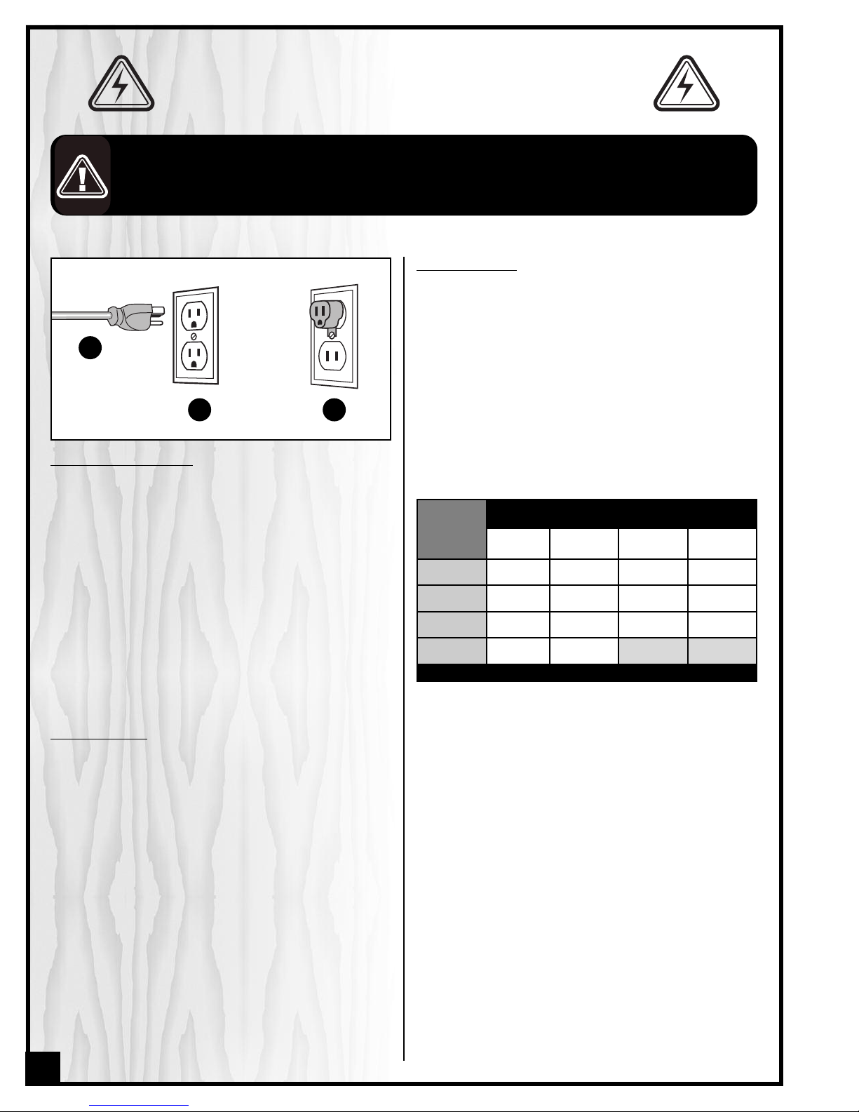
21. Make sure the tool is properly grounded. If equip-
ped with a 3-prong plug it should be used with a
three-pole receptacle. Never remove the third
prong.
22. Do not use this wood lathe for other than its
intended use. If used for other purposes,
ENERAL
INTERNATIONAL
disclaims any real implied warranty
and holds itself harmless for any injury, which may
result from that use.

GROU DI G I STRUCTIO S
In the event of an electrical malfunction or short circuit,
grounding reduces the risk of electric shock. This ma-
chine is wired for 110V single phase operation and is
equipped with a 3-conductor cord and a 3-prong
grounding plug Ato fit a grounded type receptacle B.
Do not remove the 3rd prong (grounding pin) to make
it fit into an old 2-hole wall socket or extension cord. If an
adaptor plug is used, it must be attached to the metal
screw of the receptacle C.
Note: The use of an adaptor plug is illegal in some areas.
Check your local codes. If you have any doubts or if the
supplied plug does not correspond to your electrical outlet,
consult a qualified electrician before proceeding.
CIRCUIT CAPACITY
Make sure that the wires in your circuit are capable of
handling the amperage draw from your machine, as
well as any other machines that could be operating on
the same circuit. If you are unsure, consult a qualified
electrician. If the circuit breaker trips or the fuse blows
regularly, your machine may be operating on a circuit
that is close to its amperage draw capacity. However, if
an unusual amperage draw does not exist and a
power failure still occurs, contact a qualified technician
or our service department.
BEFORE CONNECTING THE MACHINE TO THE POWER SOURCE, VERIFY THAT THE VO TAGE OF YOUR POWER SUPP Y CORRESPONDS
WITH THE VO TAGE SPECIFIED ON THE MOTOR I.D. NAMEP ATE. A POWER SOURCE WITH GREATER VO TAGE THAN NEEDED CAN
RESU T IN SERIOUS INJURY TO THE USER AS WE AS DAMAGE TO THE MACHINE. IF IN DOUBT, CONTACT A QUA IFIED E ECTRICIAN
BEFORE CONNECTING TO THE POWER SOURCE.
THIS TOO IS FOR INDOOR USE ON Y. DO NOT EXPOSE TO RAIN OR USE IN WET OR DAMP OCATIONS.
EXTE SIO CORDS
If you find it necessary to use an extension cord with
your machine, use only 3-wire extension cords that
have 3- prong grounding plug and a matching 3-pole
receptacle that accepts the tool’s plug. Repair or
replace a damaged extension cord or plug immedi-
ately.
Make sure the cord rating is suitable for the amperage
listed on the motor I.D. plate. An undersized cord will
cause a drop in line voltage resulting in loss of power
and overheating. The accompanying chart shows the
correct size extension cord to be used based on cord
length and motor I.D. plate amp rating. If in doubt, use
the next heavier gauge. The smaller the number, the
heavier the gauge.
ELECTRICAL REQUIREME TS
6
A
BC
AMPERES
(AMPS)
EXTE SIO CORD LE GTH
25 FEET 50 FEET 100 FEET 150 FEET
< 5 18 16 16 14
6 TO 10 18 16 14 12
10 TO 12 16 16 14 12
12 TO 16 14 12 * NR * NR
* NR = Not Recommended

14" x 30" WOOD LATHE
25-300QC M1
IDE TIFICATIO OF MAI PARTS A D COMPO E TS
A- MOTOR
B- BELT TENSION RELEASE LEVER
C- HEADSTOCK
D- WORK LI HT
E- TOOL REST
F- TOOL REST LOCKIN LEVER
G- TOOL REST CARRIA E LEVER
H- TOOL REST CARRIA E
I- LATHE BED
J- LIVE CENTER
K- TAILSTOCK
- QUILL MOVEMENT HAND WHEEL
M- TAILSTOCK LOCKIN LEVER
N- HEADSTOCK LOCKIN LEVER
O- FLYWHEEL
P- INDEXIN PIN (SHOWN INSTALLED)
Q- SPINDLE SPEED CONTROLLER
R- SPINDLE SPEED READ OUT
S- ON/OFF SWITCH WITH SAFETY KEY
T- SPINDLE DIRECTION SWITCH
U- HEADSTOCK PIVOT LOCKIN PIN
V- FACE PLATE
W- SPUR CENTER
X- TOOL REST SWIVEL ARM
Y- TOOL REST SWIVEL ARM LOCKIN LEVER
7
N
O
P
S
R
T
U
V
W
X
Y
A
B
E
F
D
I
J
C
G
H
K
L
M

U PACKI G
BASIC FU CTIO S
A
B
C
DE
G
F
H
J
*Already installed on the lathe
- LIVE CENTER* ..................................................................1
M- SPUR CENTER*.................................................................1
N- FACE PLATE*....................................................................1
8
K
Carefully unpack and remove the lathe and its compo-
nents from the box and check for damaged or missing
items as per the list of contents below.
NOTE: Please report any damaged or missing items to your
General International distributor immediately.
LIST OF CO TE TS QTY
A- WOOD LATHE ..................................................................1
B- STAND..............................................................................2
C- SPINDLE LOCK PIN..........................................................1
D- BELT TENSION RELEASE LEVER.........................................1
E- FACE PLATE WRENCH......................................................1
F- TOOL REST SWIVEL ARM .................................................1
G- HEX HEAD BOLT ..............................................................8
H- KNOCK OUT BAR ............................................................8
I- LEVELIN FOOT W/NUT & JAM NUT ..............................4
J- FLAT WASHER...................................................................8
K- 12 /14 MM OPEN END WRENCH...................................1
*
L
*
M
*
N
This eneral International model 25-300QC M1 Wood Lathe is designed specifically for medium to larger sized
wood turning projects. With a maximum swing over bed of 14”, a distance between centers of 30”, and 2 electron-
ically controlled variable speed ranges (170-1200 and 500-3600 RPM) with digital spindle speed display, the 25-
300QC is ideal for turnings such as chair or table legs and columns, as well as bowls of various sizes. A simple belt
re-positioning on the drive pulleys, allows the operator to select the desired speed range and the electronic speed
controller allows for further fine-tuning within each speed range.
With its pivoting head, larger bowls can also be turned on the outboard side of the lathe, with the help of an option-
al outboard turning bracket #25-305. For longer turnings an optional 18” bed extension, #25-618 can be added.
The 25-300QC M1 comes equipped with a selection of the most commonly used accessories, including a 3” face
plate for bowl turning and both live and spur center for typical spindle turning, to allow the user to begin turning
(turning tools not supplied) after a few minutes of assembly and set-up, right out of the box.
The 25-300QC M1 is designed to be compatible with all aftermarket turning accessories using MT#2 Morse taper in
both the headstock and tailstock and the headstock spindle threads are compatible with all 1” dia x 8 TPI female
threaded chucks and face plates.
I

CLEAN UP
The unpainted cast-iron surface of the lathe bed is covered with a protective coating that helps prevent rust from
forming during shipping and storage. emove this protective coating by rubbing with a rag dipped in kerosene,
mineral spirits or paint thinner. (Handle and dispose of potentially flammable solvent soaked rags according to
manufacturers’ safety recommendations.) Avoid rubbing the lathes painted surfaces as many solvent based prod-
ucts will remove paint.
To prevent rust, apply a light coating of paste wax or use regular applications of any after-market surface protec-
tant or rust inhibitor.
BE SURE TO WORK IN A WELL VENTILATED AREA FOR THE CLEAN-U ROCESS.
PLACEMENT WITHIN THE SHOP / LIFTING AND HANDLING
PLACEMENT WITHIN THE SHOP
This machine should be installed and operated only on a solid, flat and stable floor that is able to support the
weight of the lathe and the operator.
Plan for placement within your shop that will allow the operator to work unencumbered and unobstructed by foot
traffic (either passing shop visitors or other shop workers) or other tools or machinery.
THIS MODEL 25-300QC 14" X 30" WOOD LATHE IS VERY HEAVY. DO NOT OVER-EXERT. THE HEL OF AT LEAST TWO ASSISTANTS WILL
BE NEEDED FOR THE FOLLOWING STE .
TO LIMIT THE RISK OF SERIOUS INJURY OR DAMAGE TO THE MACHINE, ANY EQUI MENT USED TO LIFT THIS MACHINE (HOIST OR
FORKLIFT) SHOULD HAVE A RATED CA ACITY IN EXCESS OF 385 LBS (175 KG).
LIFTING AND HANDLING THE MACHINE
Because of its great weig t a minimum of two extra people
will be required to assist wit lifting t e wood lat e and
installing its support legs. T at being said, to limit t e risk of
serious injury or damage to t e mac ine, ideally, a oist or
lift s ould be used.
1. emove the straps and wood blocks that hold the
lathe to the pallet and remove the plastic bag.
2. Thread two leveling feet into the threaded holes of
the legs A. Loosely tighten the hex nuts against the
bottom of the legs B.
3. A) Lifting with a lift of hoist:
Lift the lathe off the pallet using a forklift or hoist, and move the lathe to the desired location then install
the wood lathe on its support legs as instructed in step 4while the lathe is still held by the forklift or hoist.
Note: Pay special attention to t e balance of t e mac ine w ile lifting. (T e motor side is muc eavier).
B) Lifting with the help of assistants:
If a forklift or hoist is not available, the help of at least
two assistants will be needed.
Note: First remove t e tailstock and tool rest/tool car-
riage to decrease t e weig t of t e lat e by loosening
and removing ex nut Con t e opening in your lat e
bed wit t e supplied 14 mm wrenc , t en removing t e
cap screw.
AB
C
9

elease the headstock locking lever Aand pull the
headstock pivot pin Bout of the 180º stop hole, then
pivot the headstock 180º and release the pivot pin so it
seats in the 0º stop hole. Lock the headstock in place
by pulling the headstock locking lever forward.
Install the belt tension release lever Cas shown in D.
INSTALL THE BELT TENSION RELEASE LEVER
REPOSITIONING THE HEADSTOCK
10
Lift the lathe and place it on a table or workbench, D,
with sufficient clearance to allow the support legs to
be attached from underneath.
4. Attach the support legs to the bed using 8 hex
head bolts with 8 flat washers E. Firmly tighten the
bolts with the supplied 14 mm wrench.
5. With the support legs firmly secured to the lathe, care-
fully lower the lathe onto the floor.
6. Adjust the leveling feet Fto ensure that all four feet sit
firmly on the floor. Make sure that the machine
does not rock.
WORKBENCH
D
F
FOR YOUR SAFETY IT IS ESSENTIAL THAT THE MACHINE DOES
NOT ROCK OR TI DURING O ERATION. U ON START-U OR
DURING O ERATION, IF YOU NOTICE ANY ROCKING, TI -
ING OR CHATTERING OF THE BASE TURN THE MACHINE
OFF IMMEDIATELY AND RE-ADJUST THE LEVELING FEET AS
NEEDED TO STABILIZE THE LATHE ON THE FLOOR.
E
B
CD
7. e-install the tool rest/tool carriage and tailstock.
A
ASSEMBLY INSTRUCTIONS
For your convenience this lathe is shipped from the factory partially assembled and requires only minimal assem-
bly and set-up before being put into service.
SERIOUS ERSONAL INJURY COULD OCCUR IF YOU CONNECT THE MACHINE TO THE OWER SOURCE BEFORE YOU HAVE COM-
LETED THE INSTALLATION AND ASSEMBLY STE S. DO NOT CONNECT THE MACHINE TO THE OWER SOURCE UNTIL INSTRUCTED
TO DO SO.
F
G
H
E
INSTALL THE TOOL REST SWIVEL ARM
1. Loosen locking lever Eand pull the tool rest out of
the tool rest carriage.
2. Install the tool rest swivel arm in the tool rest car-
riage as shown in F, then tighten locking lever E.
3. Install the tool rest in the tool rest swivel arm as
shown in Gthen tighten locking lever H.

CONNECTING TO A POWER SOURCE
SWITCH OFF
TO REDUCE THE RISK OF SHOCK OR FIRE DO NOT OPERATE THE UNIT WITH A DAMAGED POWER CORD OR PLUG.
REPLACE DAMAGED CORD OR PLUG IMMEDIATELY.
TO A OID UNEXPECTED OR UNINTENTIONAL START-UP, MAKE SURE THAT THE POWER SWITCH IS IN THE OFF POSI-
TION BEFORE CONNECTING TO A POWER SOURCE.
Refer back to the section entitled “ELECTRICAL
REQUIREMENTS” and make sure all requirements
and grounding instructions are followed.
Once the assembly steps have been completed,
uncoil the power cord and plug the power cord into an
appropriate outlet.
When turning operations have been completed
unplug the lathe from the power source.
BASIC ADJUSTMENTS & CONTROLS
REAR VIEW
ON/OFF POWER SWITCH
This lathe is equipped with a main power on/off switch
located at the rear of the machine. This adds an addi-
tional level of protection to help prevent unintentional
start-up or unauthorized use of the lathe.
After plugging in the power cord, turn on the main
power switch. The spindle speed read-out will light up
and read “0”.
The lathe is equipped with a rocker style ON/OFF
switch Alocated on the headstock, that is equipped
with a lock-out key Bto prevent unwanted or unautho-
rized start-up.
ON/OFF POWER SWITCH WITH SAFETY KEY
B
A
The spindle direction switch Callows the user to select
the forward or reverse mode.
To start the lathe, select either forward Eor reverse D
mode.
Note: When the spind e direction switch is in the OFF posi-
tion F, the unit can not be started by pu ing the ON/OFF
switch up.
F
DE
SPINDLE DIRECTION SWITCH
C
11

NOTE: If a sudden power fai ure occurs, the spind e wi not re-start automatica y when power comes back on, even if the ON/OFF
power switch is sti in the ON position. Push down on the switch to reset the switch, then pu it up to start the athe.
SAFETY KEY
(PRE ENTS START-UP
WHEN REMO ED)
POWER ON
TO PRE ENT UNWANTED OR UNAUTHORIZED START-UP OR USAGE, REMO E THE LOCK-OUT KEY AND STORE IT IN A SAFE PLACE, OUT
OF THE REACH OF CHILDREN, WHENE ER THE LATHE IS NOT IN USE.
STARTING / STOPPING THE LATHE
To start the lathe:
1. Insert the lock-out key G.
2. Select the spindle direction, either FORWARD Eor
RE ERSE D.
3. Pull up on the lower portion of the switch as shown
in H.
To stop the lathe: Push down on the switch, I.
GHI
POWER OFF
CHANGING SPINDLE SPEED
This model 25-300QC is equipped with an electronic
variable speed controller allowing the user to change
the speed (within the 2 different speed ranges: 170 to
1200 and 500 to 3600 RPM) by simply turning the speed
control dial A. The digital spindle speed readout Bwill
indicate the operating spindle speed.
Note: Turning speeds vary depending on the size and
diameter of the workpiece as we as which stage you are
at in the overa turning process. When turning a sma er
diameter workpiece, a higher spind e speed is recom-
mended. Proper spind e speed se ection comes with prac-
tice and experience and when in doubt a ways start at a
s ower speed, increasing when you are sure that it is safe
to do so.
B
A
12
WORKLIGHT
The goose neck style worklight Aon this model 25-300QC
provides
extra lighting
for added convenience. It can be
repositionned for optimal lighting of the work surface.
Note: Uses a standard type “A” maximum 40 Watt 120 vo t
app iance bu b (not inc uded).
-Turn the ON/OFF switch Bonce to turn the worklight
ON:
-Turn it once again to turn the worklight OFF:
TO REDUCE THE RISK OF FIRE, USE 40 WATT (MAXI-
MUM) 120 OLT TYPE “A” APPLIANCE BULB. DO NOT
USE STANDARD HOUSEHOLD BULBS.
A
B

Use the chart as a basic guideline for selecting the
appropriate spindle speed.
Changing between the 2 speed ranges requires
moving the drive belt from one set of drive pulleys to
another.
REFERE CE CHART FOR SPI DLE SPEED SELECTIO *
WORKPIECE
DIAMETER REVOLUTIO S PER MI UTE (RPM)
3600
2400
2 - 4”
FI ISHI G
1500
4 - 6”
1100
6 - 8”
700
8 - 10”
500
10 - 12”
1500 3000
700 1500
ROUGHI G GE ERAL
CUTTI G
500 1000
380 700
300 600
250 400
UNDER 2”
High: 500 TO 3600 RPM
Low: 170 TO 1200 RPM
SSPPEEEEDD RREECCOOMMMMEENNDDAATTIIOONNSS22 SSPPEEEEDD RRAANNGGEESS
1. To access the belt and pulleys, loosen the belt
guard lock knob A and open the belt guard locat-
ed on the headstock.
CHA GI G SPI DLE SPEED RA GE
TURN OFF AND UNP UG THE MACHINE FROM THE POWER SOURCE BEFORE OPENING THE BE T GUARD OR BEFORE PERFORMING
ANY MAINTENANCE OR ADJUSTMENTS.
A
2. Release the belt tension locking lever B.
3. Remove the tension on the belt by pulling the
belt tension release lever C towards you.
4. Set the belt by hand to the required pulley posi-
tion (High/Low), D.
5. Push the belt tension release lever C forward to re-
tension the belt, and then tighten the belt tension
locking lever B.
6. To verify the belt positioning and ensure the belt
will run smooth on the pulleys; rotate the flywheel E
by hand to turn the spindle while observing the belt
movement. If the belt moves smoothly close the belt
guard – if the belt wobbles between the pulleys
repeat steps 2-5 as needed.
B
D
400
12 - 14” 200 250
C
E
13
MOTOR
SPI DLE

The tool rest carriage can be moved along the bed
slide ways and swiveled as needed. Loosen the tool
rest carriage lever Aand move the carriage to the
desired location. Re-tighten the lever securely after
adjustment.
The tool rest swivel arm allows for even more position-
al adjustment as both the swivel arm in the tool rest
carriage mounting hole B and the tool rest in the swiv-
el arm mounting hole C can be swiveled as needed
for accurate and convenient tool rest positioning.
TOOL REST CARRIAGE & SWIVEL ARM A D TOOL REST ADJUSTME TS
MOU TI G & REMOVI G THE HEADSTOCK SPUR CE TER
A
The tool rest should be adjusted so that its top is 1/8"
above the center of the workpiece. Loosen the tool rest
locking lever D and adjust the height and position of
the tool rest as needed. Re-tighten the lever securely
after adjustment.
B
C
D
The headstock spindle has an MT#2 taper hole into
which the spur center fits A.
Note: The spur center can be installed with the face plate
installed B on or removed A (to remove the face plate, see
section “Mounting a workpiece to the face plate” on page
16).
1. Make sure the shank of the spur center and the
spindle hole are clean and free of debris and fit
the spur center firmly in the spindle hole by hand.
To remove the headstock spur center:
Knock it out from the opposite end of the spindle C
using the supplied knock-out-bar D.
Note: When knocking out the spur center, always hold it by
hand to prevent it from falling E.
MOU TI G & REMOVI G THE HEADSTOCK SPUR CE TER
AB
14
D
C
E

The tailstock has an MT#2 taper hole into which the live
center fits.
1. Make sure the shank of the live center and the tail-
stock hole are clean and free of debris and fit the
live center firmly in the hole by hand A.
To remove the live center from the tailstock quill:
Loosen the tailstock quill locking lever Band move the
quill out by turning the quill movement hand wheel C
until the quill end is nearly inside the tailstock and the
live center can be removed by hand.
Note: When removing the live center, always hold it by
hand to prevent it from falling D.
MOU TI G & REMOVI G THE TAILSTOCK LIVE CE TER
A
D
B
C
The tailstock quill can be moved in and out of the tail-
stock casting E by turning the tailstock quill movement
hand wheel F.
To move the tailstock quill:
1. Loosen the quill locking lever G.
2. Turn the the quill movement hand wheel to move
the quill as needed.
3. Re-tighten the quill locking lever to secure the quill
in position.
MOVI G TAILSTOCK QUILL I / OUT
G
E
F
The tailstock is used to support the other end of the
workpiece to be turned and can be moved along the
bed slideways to suit the length of the workpiece H.
To move the tailstock on the bed:
1. Loosen the tailstock locking lever I.
2. Move the tailstock by hand to the desired location
on the bed J.
3. Retighten the tailstock locking lever to secure the
tailstock in position.
TAILSTOCK MOVEME T
E
I
15
HJ
TAILSTOCK REAR VIEW

MOU TI G A WORKPIECE TO THE FACE PLATE
For turning applications where the workpiece cannot
be secured between the headstock and tailstock cen-
ters (such as bowl turning) the face plate must be used
to secure the workpiece to the headstock spindle.
1. Unlock the face plate by loosening and removing
the two set screws Ausing a 3 mm Allen key.
2. Loosen the face plate by inserting the supplied
spindle lock pin B in one of the spindle holes to
keep the spindle from turning, while loosening the
face plate using the supplied face plate wrench, as
shown in C.
3. Unscrew and remove the face plate, D.
4. With the face plate removed from the lathe,mount
the workpiece onto the face plate with wood
screws (not included) through the mounting holes
from the back of the face plate.
Note: Make sure the screws are not so long that they
will enter the area of the workpiece where the materi-
al is to be removed.
5. Thread the face plate back on the lathe and tight-
en using the spindle lock pin and face plate
wrench.
E
D
TOP VIEW B
C
PIVOTI G THE HEADSTOCK (FOR OUTBOARD TUR I G)
1. Release the heastock locking lever A.
2. Pull up on the headstock pivot pin to release the
headstock B.
16
The headstock pivots 360° with positive stops at 45°, 90°, 135° and 180° for multi-position outboard turning. Larger
bowls can also be turned on the outboard side of the lathe, with the help of an optional outboard turning brack-
et #25-305. To pivot the headstock:
3. Rotate the headstock to the desired position C and
release the pivot pin so it seats in the correspond-
ing stop hole D.
4. Secure the headstock in place by pulling the
headstock locking lever A forward.
NEVER TURN ON THE ATHE WHEN THE HEADSTOCK SPIND E IS OCKED IN P ACE. A WAYS, TURN OFF AND UNP UG THE ATHE FROM THE
POWER SOURCE, BEFORE INSERTING THE INDEXING PIN TO OCK THE SPIND E.
TURNING ON THE ATHE AFTER THE SPIND E OCK PIN (OR ANY OTHER OBJECT) HAS BEEN INSERTED INTO THE HEADSTOCK INDEXING
HO E, THEREBY PREVENTING THE HEADSTOCK SPIND E FROM TURNING, CAN EAD TO SERIOUS INJURY, DAMAGE TO THE WORKPIECE, OR
DAMAGE TO THE ATHE AND THE MOTOR.
A
C
D
B
A

I DEXI G
For advanced turners, the indexing features on this 25-300QC M1 lathe allows the user to lock the spindle in place
at 36 evenly spaced 10° intervals while the workpiece is installed between the centers. This is primarily used for reed-
ing or fluting (cutting decorative grooves vertically up the length of the spindle) usually with the help of a shop
made jig and router.
NEVER TURN ON THE ATHE WHEN THE HEADSTOCK SPIN-
D E IS OCKED IN P ACE. A WAYS, TURN OFF AND
UNP UG THE ATHE FROM THE POWER SOURCE, BEFORE
INSERTING THE INDEXING PIN TO OCK THE SPIND E.
TURNING ON THE ATHE AFTER THE INDEXING PIN (OR
ANY OTHER OBJECT) HAS BEEN INSERTED INTO THE HEAD-
STOCK INDEXING HO E, THEREBY PREVENTING THE HEAD-
STOCK SPIND E FROM TURNING, CAN EAD TO SERIOUS
INJURY, DAMAGE TO THE WORKPIECE, OR DAMAGE TO THE
ATHE AND THE MOTOR.
To lock the spindle:
1. Loosen the indexing pin A.
2. While slowly turning the flywheel B by hand, press
the indexing pin in until the pin finds and bottoms
out in an indexing hole, then re-tighten the index-
ing pin.
3. Complete the desired cut, groove or other opera-
tion on the spindle.
4. If further grooves are required, loosen the pin
again and slowly turn the spindle until the pin locks
into the next, or the desired position.
Note: There are 36 evenly spaced holes in the headstock
spindle allowing for indexing at 10° increments (360°/36
positions = 10°) C, allowing for a wide variety of symmet-
rical decorative grooves or patterned cuts.
A
B
C
CHECKI G ALIG ME T BETWEE CE TERS
There is a small amount of play built into the head-
stock on the bed to allow the headstock to pivot freely.
Whenever the headstock is pivoted back from the out-
board position, the alignment between the headstock
and tailstock centers should be double checked and
adjusted as needed.
1. Pivot the headstock to its normal spindle turning
position (0º) and lock it in place.
2. Install a spur center in the headstock and a
live center in the tailstock.
3. Release the tailstock locking lever and advance
the tailstock on the bed Auntil the points of the 2
centers just barely touch each other.
4. Using the tailstock locking lever, secure the tail
stock on the bed with the points still touching.
5. Look down at the two centers from above B to ve-
rify that the points are in alignment. If the points line
up, proceed with normal turning operations.
6. If the points are not lined up release the head-
stock locking lever and manually adjust the
headstock position using the play in the head-
stock to line up the center points C.
7. With the points lined up, hold the headstock in
place and tighten the headstock locking lever.
8. With the points lined up, proceed with normal
turning operations.
B
C
17
TOP VIEW
A

PERIODIC MAI TE A CE
•Keep the unit clean and free of dust by wiping with a cloth or vacuuming off any woodchips or dust after
each use.
•All bearings are sealed and permanently lubricated and no further lubrication is required.
•Regular applications of a surface protectant/lubricant will help prevent rust and keep the tool rest, head, and
tailstock sliding smooth on the bedway.
•Periodically inspect the power cord and plug for damage. Replace the power cord and the plug at the first
signs of visible damage.
RECOMME DED OPTIO AL ACCESSORIES
5 Piece Woodturning Mini-
Chisel Set - #25-250
Made from high quality high-
speed steel with solid hard-
wood handles.
Designed specially for small-
er turning such as pen mak-
ing and other small hobby
type projects.
Includes a 3/4” diamond part-
ing tool, a 1/2” round nose
scraper, a 1” skew chisel, and
a 1/2” bowl gouge.
18” Bed Extension
#25-618
For longer turnings an
optional 18” bed exten-
sion, can be added.
Outboard Turning Bracket
#25-305
Larger bowls can be turned on
the outboard side of the lathe,
with the help of an optional out-
board turning bracket.
A large range of optional aftermarket accessories can be used with this lathe. Your local dealer may be able to
offer suggestions based on what is readily available in your area.
Key issues to keep in mind when shopping for aftermarket accessories are:
We also offer a large variety of products to help you increase convenience, productivity, accuracy and safety
when using your wood lathe Here’s a small sampling of optional accessories available from your local eneral
International dealer.
For more information about our products, please visit our website at www.general.ca
4 Piece Woodturning Chisel Set - #25-210
Made from hi-speed steel this kit comes in it’s own wood-
en carrying case and features 4 of the most commonly
used turning tools including a 3/4” parting tool, a 1/2”
round nose scraper, a 1” skew chisel and 1/2” bowl
gouge.
Headstock and tailstock feature a MT#2 taper – to avoid damaging the lathe use only headstock and tailstock
centers with a matching taper.
Headstock spindle threads are 1” diameter x 8 threads per inch (T.P.I.) – to avoid stripping or damaging the
threads, use only threaded headstock attachments (such as face plates and jaw chucks) that have matching
threads.
18

WIRING DIAGRAM
19
NOTE: I a ilter is required or reducing EMI (Electro Magnetic Inter erence), install it as close as possible to the AC drive.
EMI can also be reduced by lowering the carrier requency. When using a GFCI (Ground Fault Circuit Interrupt), select cur-
rent sensor with sensitivity o 200ma, and not less than 0.1-second detection to avoid nuisance tripping.

55
58 115
37 67
30A
31
103
33 32
113
112
122
111
120
38
67
32 121
133
117
116
9
29A
24
51 56
25
40
9
27 41
42
44
65
37
70
5
106
105
104 6
43
3
2
1
9
69
62
61
61
63 61
65 49
44
12
135
134
108
113
46A
45A
4
19A
47
48
28A
15A
114
65
16
18
17
14
101A
37
44
35
50
68
11
26
65
36A
10A
98132
7
114
119
109
108
107
118
55
44
20
130 60
59
66
54
52
109
110
107
DIAGRAM A
20
Table of contents
Other General International Power Tools manuals

General International
General International Excalibur EXF-30S-R30 Parts list manual

General International
General International 75-075 Manual

General International
General International DP2006 Manual instruction

General International
General International 75-155 Parts list manual

General International
General International 45-100 Parts list manual

General International
General International DP2003 Parts list manual

General International
General International 40-350 User manual

General International
General International DP2002 Parts list manual

General International
General International 80-250 Parts list manual

General International
General International DP2001 Parts list manual