General International Excalibur 40-100 Parts list manual

EATURES
Heavy-duty massive router lift with 9 1/4" x
11 3/4" aluminum top plate.
Stable 4 post/lift screw design & chain drive
lifting system controlling all 4 corners simul-
taneously.
its all fixed base router motors.*
Smooth above-the-table adjustment mech-
anism for fast tool changes & precision bit
setting.
Available with table in either cast-iron (40-
100C), MD (40-100M) or Phenolic (40-100P).
Sturdy steel stand includes easy access
on/off safety switch with removable lock-
out key & non-slip rubber feet.
ence has 2 1⁄4" dust collection outlet and
adjustable scales.
Under table steel dust enclosure with
access door, adjustable air vent, power
cord grommet and 4" dust port with 2 1⁄4"
branch inlet to the fence. Includes 2 1⁄4"
dust hose and 2 hose clamps.
Some router models may require reducer
collars/adaptors.
SPECI ICATIONS
OVERALL DIMENSIONS
30 1/2" X 16" X 21” (775 X 406 X 533 MM)
TABLE SIZE
Cast-iron: 16" X 27”(406 X 686 MM)
Phenolic & MD : 15 3/4" X 25 5/8” (400 X 651 MM)
TABLE HEIGHT
16” (406 MM)
ENCE SIZE (EACH)
3” X 15 1/4" X 3/4” (76 X 387 X 19 MM)
MAXIMUM ENCE TRAVEL
6” (152 MM)
DUST OUTLET
2 1/4” (57 MM)
DISTANCE BETWEEN T-SLOT & SPINDLE CENTER
3/4": 5 1/16” (135 MM)
3/8": 6 9/16" (167 MM)
DISTANCE ROM SPINDLE CENTER TO RONT
EDGE O TABLE
8" (205 MM)
T-SLOT DIMENSIONS
3/4” X 13/32” (19 X 10 MM) /
3/8" X 9/32" (10 X 7 MM)
ROUTER INSERT PLATE
9 1/4” X 11 3/4 (235 X 298 MM)
TABLE OPENING SIZES - DIAMETER
PLATE: 3 3/4” (95 MM)
INSERT RING: 1 1/2” (38 MM)
NET WEIGHT (40-100C MODEL)
119 LBS (54 KG)
SETUP & OPERATION MANUAL
MODEL
#40-100
DELUXE ROUTER TABLE KIT
(Bench top model)
VERSION 2 _ REVISION 2_DECEMBER 2013
© Copyright General® International
*

THANK YOU for choosing this Excalibur by General®International model
40-100 Deluxe Router Table Kit (bench top model). This router table has been carefully tested
and inspected before shipment and if properly used and maintained, will provide you with
years of reliable service. or your safety, as well as to ensure optimum performance and trou-
ble-free operation, and to get the most from your investment, please take the time to read this
manual before assembling, installing and operating the unit.
The manual’s purpose is to familiarize you with the safe operation, basic function, and features
of this router table as well as the set-up, maintenance and identification of its parts and com-
ponents. This manual is not intended as a substitute for formal woodworking instruction, nor to
offer the user instruction in the craft of woodworking. If you are not sure about the safety of
performing a certain operation or procedure, do not proceed until you can confirm, from
knowledgeable and qualified sources, that it is safe to do so.
Once you’ve read through these instructions, keep this manual handy for future reference.
Disclaimer: The information and specifications in this
manual pertain to the unit as it was supplied from the
factory at the time of printing. Because we are commit-
ted to making constant improvements, General®
International reserves the right to make changes to
components, parts or features of this unit as deemed
necessary, without prior notice and without obligation to
install any such changes on previously delivered units.
Reasonable care is taken at the factory to ensure that
the specifications and information in this manual corres-
ponds with that of the unit with which it was supplied.
However, special orders and “after factory” modifica-
tions may render some or all information in this manual
inapplicable to your machine. urther, as several gene-
rations of this model of router table and several versions
of this manual may be in circulation, if you own an ear-
lier or later version of this unit, this manual may not
depict your machine exactly. If you have any doubts or
questions contact your retailer or our support line with
the model and serial number of your unit for clarifica-
tion.
GENERAL® INTERNATIONAL
8360 Champ-d’Eau, Montreal (Quebec) Canada H1P 1Y3
Telephone (514) 326-1161 • ax (514) 326-5555 • www.general.ca

GE ERAL® I TER ATIO AL WARRA TY
All component parts of General® International and Excalibur by General International® prod-
ucts are carefully inspected during all stages of production and each unit is thoroughly
inspected upon completion of assembly.
Limited Lifetime Warranty
Because of our commitment to quality and customer satisfaction, General® International
agrees to repair or replace any part or component which upon examination, proves to be
defective in either workmanship or material to the original purchaser for the life of the tool.
However, the Limited Lifetime Warranty does not cover any product used for professional or
commercial production purposes nor for industrial or educational applications. Such cases
are covered by our Standard 2-year Limited Warranty only. The Limited Lifetime Warranty is also
subject to the “Conditions and Exceptions” as listed below.
Standard 2-Year Limited Warranty
All products not covered by our lifetime warranty including products used in commercial,
industrial and educational applications are warranted for a period of 2 years (24 months) from
the date of purchase. General® International agrees to repair or replace any part or compo-
nent which upon examination, proves to be defective in either workmanship or material to the
original purchaser during this 2-year warranty period, subject to the “conditions and excep-
tions” as listed below.
To file a Claim
To file a claim under our Standard 2-year Limited Warranty or under our Limited Lifetime
Warranty, all defective parts, components or machinery must be returned freight or postage
prepaid to General® International, or to a nearby distributor, repair center or other location
designated by General® International. or further details call our service department at 1-888-
949-1161 or your local distributor for assistance when filing your claim.
Along with the return of the product being claimed for warranty, a copy of the original proof
of purchase and a “letter of claim” must be included (a warranty claim form can also be used
and can be obtained, upon request, from General® International or an authorized distributor)
clearly stating the model and serial number of the unit (if applicable) and including an expla-
nation of the complaint or presumed defect in material or workmanship.
CONDITIONS AND EXCEPTIONS:
This coverage is extended to the original purchaser only. Prior warranty registration is not
required but documented proof of purchase i.e. a copy of original sales invoice or receipt
showing the date and location of the purchase as well as the purchase price paid, must be
provided at the time of claim.
Warranty does not include failures, breakage or defects deemed after inspection by General®
International to have been directly or indirectly caused by or resulting from; improper use, or
lack of or improper maintenance, misuse or abuse, negligence, accidents, damage in han-
dling or transport, or normal wear and tear of any generally considered consumable parts or
components.
Repairs made without the written consent of General® International will void all warranty.

TABLE OF CO TE TS
Rules for safe operation ...............5
Installation ........................6
Safety ............................6
Identification of main parts
and components ....................7
Unpacking .........................8
List of contents - 40-060 Stand . . . . . . . . . . . . . . . . .8
List of contents - 40-065 Router fence . . . . . . . . . . .8
List of contents - 40-125 Router lift . . . . . . . . . . . . . .9
List of contents - 40-130 Dust collection kit . . . . . . .9
List of contents - Table . . . . . . . . . . . . . . . . . . . . . . .10
Additional requirements for set up . . . . . . . . . . . .10
Assembly instructions .............11-22
40-060 Router table stand . . . . . . . . . . . . . . . .11
Table 40-070/40-047/40-043 . . . . . . . . . . . . . .13
Cleaning the cast-iron table (for #40-100 only) . .13
Install the table (cast-iron table #40-100C and
phenolic table # 40-100P only) . . . . . . . . . . . . . . .13
Attach the table to the stand (cast-iron #40-100C
and phenolic #40-100P only) . . . . . . . . . . . . . . . .14
40-065 Router fence . . . . . . . . . . . . . . . . . . . .14
Prepare the table for router lift . . . . . . . . . . . .18
40-130 Dust collection kit . . . . . . . . . . . . . . . .19
Mountingarouter ......................20
Leveling and locking the router plate . . . . . . . . .22
Insertringremoval..........................22
Installing the starting pin . . . . . . . . . . . . . . . . . . . .22
Basic adjustments & controls ........23-24
Adjusting the fence along the rails . . . . . . . . . . . .23
Adjusting the sliding scale on the rails . . . . . . . . .23
Adjusting the fence faces . . . . . . . . . . . . . . . . . . . .23
Connecting the router to the safety switch . . . . .23
Using the safety switch . . . . . . . . . . . . . . . . . . . . . .24
Connecting to a dust collector . . . . . . . . . . . . . . .24
Operating instructions .................24-26
Before starting . . . . . . . . . . . . . . . . . . . . . . . . . . . . .24
Using the spacer bars for jointing . . . . . . . . . . . . .25
Jointing . . . . . . . . . . . . . . . . . . . . . . . . . . . . . . . . . . .25
Groove cutting . . . . . . . . . . . . . . . . . . . . . . . . . . . . .26
Profile cutting . . . . . . . . . . . . . . . . . . . . . . . . . . . . . .26
Tensioning the drive chain . . . . . . . . . . . . . . . . . . .26
Recommended optional accessories .....27
Parts list & diagrams ..............28-34
Contact information .................35

1.Make sure that the operator has been properly
trained and has read and understands the Owner’s
Manual before operating any machinery.
2. Be sure to read, understand and follow all instructions,
warnings and safety guidelines supplied with your
router.
3. Do not operate this router table when tired, distracted,
or under the effects of drugs, alcohol or any medica-
tion that impairs reflexes or alertness.
4. Keep the work area well lit, clean and free of debris.
5. Stay Alert! Give your work your undivided attention.
Even a momentary distraction can lead to serious
injury.
6. Do not wear loose clothing, gloves, bracelets, neck-
laces, or other jewelry. Wear face, eye, ear, respiratory
and body protection devices. Wear protective hair
covering to contain long hair and wear non-slip
footwear.
7. Keep hands and other body parts well away from bits
or cutting tools. When working close to the cutting tool,
always use a feather board or push-stick to hold or
guide the workpiece. Do not clear chips and sawdust
away with hands. Use a brush.
8. ine particulate dust is a carcinogen that can be haz-
ardous to health. Always work in a well ventilated area
and whenever possible use a dust collector to mini-
mize health hazards.
9. Be sure the router is running up to speed before feed-
ing the workpiece.
10. Use a suitable support if stock does not have a flat
surface.
11. Keep children and visitors at a safe distance when the
router is in operation – do not permit them to operate
the router and table.
12. Childproof and tamper proof your shop and all
machinery with locks, master electrical switches and
switch keys, to prevent unauthorized or unsupervised
use.
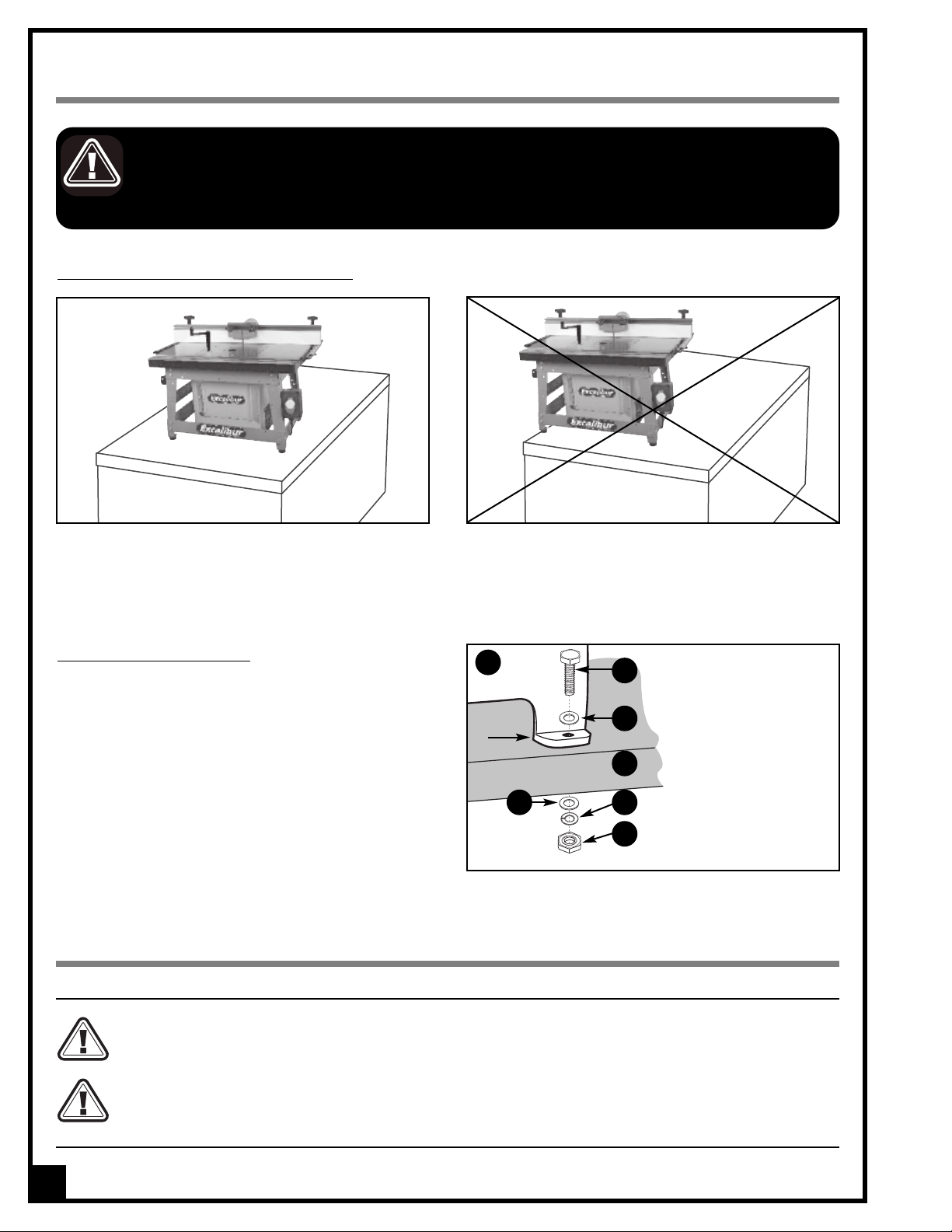
13. Secure the table to a work surface and never stand or
lean on it. Serious injury could occur if the table is
tipped or if unintentional contact is made with spin-
ning router bit.
14. Keep all guards and safety devices in place and in
good working order. If a guard must be removed for
maintenance or cleaning make sure it is properly re-
installed before using the machine again.
15. Hold the workpiece firmly against the table and use
suitable support if the workpiece does not have a flat
surface.
16. eed the stock into the bit against the rotation direc-
tion of the bit. Never run the stock between the fence
and the bit.
17. Do not operate with a damaged bit in the router.
18. Always disconnect the router from the power source
before changing accessories or before performing
any maintenance and adjustments or if the machine
will be left unattended.
19. Be sure that all adjustment tools, wrenches or other
clutter are removed from the table surface and safely
stored before routing.
20. Make sure the routers switch is in the “O ” position
before plugging in to a power source.
21. Avoid working from awkward or off balance positions.
Do not overreach and always keep both feet firmly on
the floor.
22. Never leave the router unattended while running or
with the power on.
23. Do not use this router table for any purpose other than
its intended use. If used for other purposes, GENERAL®
INTERNATIONAL disclaims any real or implied warranty
and holds itself harmless for any injury which may
result from such use.
Rules for Safe Operation
To help ensure safe operation, please take a moment to learn the machine’s applications and limitations, as well as poten-
tial hazards. General® International disclaims any real or implied warranty and holds itself harmless for any injury that
may result from improper use of its equipment.
5

I STALLATIO
6
THE MACHINE IS HEAVY (119 LBS - 54 G). DO NOT OVEREXERT. ARRANGE TO HAVE HELP NEARBY AND READY FOR UNPAC -
ING AND SET UP.
SERIOUS PERSONAL INJURY COULD OCCUR IF YOU CONNECT THE MACHINE TO THE POWER SOURCE BEFORE YOU HAVE COM-
PLETED THE INSTALLATION AND ASSEMBLY STEPS. DO NOT CONNECT THE MACHINE TO THE POWER SOURCE UNTIL INSTRUCTED
TO DO SO.
SAFETY
ROUTING MAY PRESENT SERIOUS INJURY HAZARDS TO UNTRAINED USERS. BE SURE TO READ, UNDERSTAND, AND FOL-
LOW ALL INSTRUCTIONS AND SAFETY GUIDELINES SUPPLIED WITH THE ROUTER YOU WILL INSTALL ON THIS TABLE.
MA E SURE THAT ADEQUATE HEARING PROTECTION IS USED AND THAT THE OVERALL SOUND LEVEL WITHIN THE WOR -
ING ENVIRONMENT IS TA EN INTO CONSIDERATION.
I STALL THE ROUTER TABLE O A STABLE SURFACE
MOU TI G TO A WORK SURFACE
If a permanent shop placement is practical, consider
removing the rubber feet on the base and drilling
matching through holes in the mounting surface of your
workbench or stand to bolt the table in place (hard-
ware not included) on your workbench.
If a permanent installation is not practical, clamps can
also be used to secure the table to a bench or work
table.
The unit should be installed on a flat, sturdy and stable
surface or workbench able to support the weight of
the machine and the workpiece with ease.
ORDER OF ASSEMBLY
D
A
C
E F
G
B
A- Stand legs
B- Hex head bolt
C- lat washer
D- Workbench or stand
E- lat washer
- Lock washer
G- Hex nut
Never install the machine over the edge of a table
or workbench.

DELUXE ROUTER TABLE KIT (Bench top model)
Model #40-100
IDE TIFICATIO OF MAI PARTS A D COMPO E TS
A
A- ON/O SWITCH WITH REMOVABLE SA ETY KEY
B- TABLE*
C- ENCE RAIL WITH SLIDING SCALE
D- SLIDING ADJUSTABLE ENCE ACE
E- ENCE LOCKING HANDLE
F- ROUTER LI T CRANK HANDLE
G- DUST SHIELD LOCK KNOB
H- DUST SHIELD
I- ENCE BODY
J- 3/4” X 3/4” MITER T-SLOT ( OR MITER GAUGE)
- 3/8” MITER T-SLOT ( OR SEL MADE JIGS)
L- STAND
M- DUST ENCLOSURE
N- RUBBER EET
O- DUST VENT
P- ROUTER LI T HANDLE HOLDER
* Model 40-100C Cast-iro table show .
B
C
E
D
F
GG
H
I
E
C
J
K
L
M
N
O
Q- 2 1⁄4" BRANCH INLET
R- DUST HOSE
S- 4" DUST PORT
T- DOVETAIL SLOT
Q
R
S
REAR VIEW
7
T

Carefully unpack and remove the components of the following 5 boxes - that make up a complete Excalibur Router
Table - and check for damaged or missing items as per the list of contents below.
NOTE: Please report any damaged or missing items to your General International distributor immediately.
U PACKI G
40-060 STA D (40-100)
LIST OF CO TE TS QTY
40-060 STAND (40-100)
a- CARRIAGEBOLT......................34
b- HEXNUT ............................34
c- LATWASHER ........................34
d- ROUTER LI T CRANK HANDLE HOLDER . . . . .1
e- HEXNUT(SMALL) .....................4
f- RUBBER OOT ........................4
g- PHILLIPSSCREW .......................4
h- HEXNUT .............................4
i- HEXNUT .............................4
j PHILLIPS SCREW (SMALL) . . . . . . . . . . . . . . .2
k- SWITCHBOX .........................1
l- LONG BOTTOM CROSS BRACE (REAR) . . . .1
m- LONG BOTTOM CROSS BRACE ( RONT) . . .1
n- MIDDLE CROSS BRACE (LE T) . . . . . . . . . . . .1
o- SHORT BOTTOM CROSS BRACE (L & R) . . . .2
p- SHORT TOP CROSS BRACE (L & R) . . . . . . . .2
q- LONG TOP BRACE ( RONT & REAR) . . . . . . .2
r- LEG .....................................4
40-065 ROUTER FE CE (40-100)
LIST OF CO TE TS QTY
40-065 ROUTER FENCE (40-100)
a DUSTSHIELD ..........................1
b- 2 1⁄4" dust collection outlet. . . . . . . . . . . . .1
c- ENCE LOCKING HANDLE . . . . . . . . . . . . . .2
d- ENCEBODY .........................1
e- ENCE ACE ...........................2
f ENCE SIDE RAIL W/SCALE . . . . . . . . . . . . . . .2
g- ENCE MOUNTING BRACKET . . . . . . . . . . . .2
h- SPACER BARS ( OR JOINTING WORK) . . . . .2
i- LOCKKNOB..........................8
j- T-BOLT(LONG)........................6
k- CAPSCREW ..........................6
l- PLASTICSPACER.......................2
m- LAT WASHER (SMALL) . . . . . . . . . . . . . . . . .14
n- T-BOLT(SHORT) .......................2
o- PHILLIPS HEAD SCREW . . . . . . . . . . . . . . . . . .2
p- HEXNUT(LARGE) .....................2
q- LAT WASHER (LARGE) . . . . . . . . . . . . . . . . .2
r- SQUARENUT .........................8
s- HEXHEADBOLT .......................6
a
b
c
e
g
f
h
i
d
jnpq
s
r
k
l
o
8
m
g
f
h
i
k
a
b
c
d
X 34
lm
n
o
p
q
ej
r

Carefully unpack and remove the components of the following 5 boxes - that make up a complete Excalibur Router
Table - and check for damaged or missing items as per the list of contents below.
NOTE: Please report any damaged or missing items to your General International distributor immediately.
U PACKI G (C T’D)
40-125 ROUTER LIFT
LIST OF CO TE TS QTY
40-125 ROUTER LIFT
a- ROUTERLI T ...........................1
b- ROUTER LI T CRANK HANDLE . . . . . . . . . . . . .1
c- INSERT RING WRENCH . . . . . . . . . . . . . . . . . . .1
d-STARTERPIN............................1
e- HEX SOCKET HEAD BOLT . . . . . . . . . . . . . . . . . .2
f- 2.5MMALLENKEY......................1
g- 3MMALLENKEY .......................1
h- 4MMALLENKEY .......................1
i- 6MMALLENKEY .......................1
LIST OF CO TE TS QTY
40-130 DUST COLLECTION IT
a- RIGHTSIDEPANEL ......................1
b- BOTTOMPANEL ........................1
c- REARPANEL ...........................1
d-LE TSIDEPANEL ........................1
e- RONTPANEL ............................1
f- DUSTHOSE ..............................1
g- DUSTPORT ............................1
h- HOSECLAMP ..........................2
i- HEXHEADBOLT ........................6
j- LOCKWASHER .........................6
k- LATWASHER ..........................6
l- PHILLIPS HEAD SCREW (SHORT) . . . . . . . . . .22
m- PHILLIPS HEAD SCREW (LONG) . . . . . . . . . . . .3
a
bc
de
f g hi
40-130 DUST COLLECTIO KIT
a
b
c
de
f
g
h
i
k
jl
m
9

Carefully unpack and remove the components of the following 5 boxes - that make up a complete Excalibur Router
Table - and check for damaged or missing items as per the list of contents below.
NOTE: Please report any damaged or missing items to your General International distributor immediately.
U PACKI G (C T’D)
Model 40-100C:
LIST OF CO TE TS QTY
a- 16” X 27” CAST-IRON TABLE (#40-070) . . . . . . 1
b- HEX NUT . . . . . . . . . . . . . . . . . . . . . . . . . . . . 10
c- LEVELER SCREW . . . . . . . . . . . . . . . . . . . . . . 10
d- LAT WASHER. . . . . . . . . . . . . . . . . . . . . . . . . . 4
e- LOCK WASHER . . . . . . . . . . . . . . . . . . . . . . . . 4
f- HEX SOCKET CAP SCREW . . . . . . . . . . . . . . . 4
Model 40-100P:
LIST OF CO TE TS QTY
a- 15 3/4” X 25 5/8” PHENOLIC TABLE (#40-043) 1
b- HEX NUT . . . . . . . . . . . . . . . . . . . . . . . . . . . . 10
c- LEVELER SCREW . . . . . . . . . . . . . . . . . . . . . . 10
d- LAT WASHER. . . . . . . . . . . . . . . . . . . . . . . . . . 4
e- LOCK WASHER . . . . . . . . . . . . . . . . . . . . . . . . 4
f- HEX SOCKET CAP SCREW . . . . . . . . . . . . . . . 4
Model 40-100M:
LIST OF CO TE TS QTY
a- 15 3/4” X 25 5/8” MD TABLE (#40-047) . . . . 1
b- WOOD SCREW . . . . . . . . . . . . . . . . . . . . . . . 10
c- WOOD NUT. . . . . . . . . . . . . . . . . . . . . . . . . . . 2
d WOOD SCREW . . . . . . . . . . . . . . . . . . . . . . . 26
10
Mounting hardware for #40-047 - MDF table (for model 40-100M)
ADDITIO AL REQUIREME TS FOR SET UP
• Extra person for help with lifting
(cast-iron table)
• Straight edge
• Phillips screwdriver
• Socket wrench set
• Wrench set
• Allen key set
b
c
f
Mounting hardware for #40-043 - Phenolic table (for model 40-100P)
d
e
b
f
Mounting hardware for #40-070 Cast-iron table (for model 40-100C)
c
a
Additio al hardware is supplied with the cast–iro table to allow for
i stallatio o a table saw as part of kit #40-070EK. Complete mou t-
i g i structio s for the 40-070EK ca be dow loaded at the Ge eral
I ter atio al website at: www.general.ca/manuals
d
e
d
b
c
a
a

ASSEMBLY I STRUCTIO S
SERIOUS PERSONAL INJURY COULD OCCUR IF YOU CONNECT THE MACHINE TO THE POWER SOURCE BEFORE YOU HAVE COMPLE-
TED THE INSTALLATION AND ASSEMBLY STEPS. DO NOT CONNECT THE MACHINE TO THE POWER SOURCE UNTIL INSTRUCTED TO DO
SO.
4. Using the same hardware, attach a second leg to
the top cross brace, I, then attach the second top
brace Jto this leg, as shown.
G
3. Using 4 carriage bolts with flat washers and hex nuts,
F, attach one leg to one top brace and one top
cross brace as show in G, in the assembly order
shown in H.
2. Lay the stand braces and legs on the floor as
shown. This will help you to rapidly locate the
braces and know what to attach where.
Note: Bottom brace C goes on the rear of the stand and
bottom brace D goes on the front. Put middle cross brace,
E, aside for now.
1. Attach a rubber foot to each leg using a phillips
screw, flat washer and hex nut A, in the assembly
order shown in B.
REAR
FRO T
FH
I
J
5. Attach a third leg to the top brace J, then attach
second top cross brace L, then fourth leg M.
K
J
M
6. Attach the rear bottom cross brace Nand the front
bottom cross brace Oas shown.
N
O
11
AB
40-060 ROUTER TABLE STA D
L
CD
E
Note: Do not tighten the stand bolts until after you have fastened the stand to the router table top. (See step 3 on
page 14.)

7. Attach the two bottom side cross braces, Pand Q.
8. Turn the stand in the upright position and attach
the middle cross brace on the left side, as shown
in R.
9. Using a carriage bolt, flat washer and nut, S,
attach the router lift crank handle holder Tto the
middle cross brace as shown in U.
The router lift crank handle may be stored on the holder as
shown in Vwhen not being used.
10. Stand assembly is now complete.
RU
S
T
V
11. Insert a phillips head screw with hex nut through
both holes on the middle cross brace, and from
the other side of the brace, lightly thread a hex
nut to lock the screws in position W.
The insert ring wrench may be stored on one of the
screws as shown above.
W
9. Install the switch box by sliding it’s mounting brack-
et over the right front leg X, and attach with the two
phillips head screws and washers already mount-
ed to the bracket.
X
12
Q

The protective coating on the cast-iron table, prevents rust
from forming during shipping and storage. Remove it by
rubbing with a rag dipped in kerosene, mineral spirits or
paint thinner. (Dispose of potentially flammable solvent-
soaked rags according to manufacturer’s safety recom-
mendations.)
A putty knife, held flat to avoid scratching the surface,
may also be used to scrape off the coating followed by
clean-up with solvent.
To prevent rust, apply a light coating of paste wax or use
regular applications of any after-market surface protec-
tant or rust inhibitor.
Tip: With a screw driver, push a solvent-saturated rag into
the T-slots to remove the grease.
CLEA I G THE CAST-IRO TABLE FOR #40-100C O LY)
I STALL THE TABLE (CAST-IRO TABLE #40-100C A D PHE OLIC TABLE#40-100P O LY)*
* or #40-047 MD table (for #40-100M), only thread in all leveler screws and nuts as shown below. You will use
the wood screws supplied with your table in the upcoming steps to attach the table and dust collection box
to the stand, and the fence mounting rails to the table.
C
B
A
5. As a precaution, thread in all fasteners as shown to
make sure there are no filings in any of the threaded
holes, and leave the fasteners in the underside of the
table. Only remove as assembly is taking place.
Note 1: The leveler screws need to be inserted from the
bottom of the table. The nut will sit on the top side of the
flange that the router lift/plate will rest on, A.
Note 2: There are 3 holes on each side of the table open-
ing, C. The two outside holes are for the leveling screws,
A, and the middle hole is used to secure a plate, or the
lift, to the table.
13
There are 3 different table options for Deluxe Router Table Kit, model 40-100:
Cast-iron table (#40-070) for 40-100C MD table (#40-047) for 40-100M Phenolic table (#40-043) for 40-100P
TABLE 40-070/40-047/40-043

3. Turn the stand and table assembly upright and tight-
en all bolts.
Note: If you previously threaded all the fasteners into the
underside of the cast-iron table, the leveler screws will
already be in place. If you didn’t, thread them in now. The
nut will sit on the top side of the flange that the router
lift/plate will rest on.
CAST-IRO TABLE #40-100C A D PHE OLIC TABLE #40-100P O LY)*
Note: You will find 6 additional side bracket mounting fasteners in the fence hardware to attach the side brackets to the
cast iron table. These will not be required if you have purchased a complete kit, because the same fasteners have been
supplied with the table top.
or #40-047 MD table (for #40-100M), use the wood screws supplied with your table to attach the mounting brackets
to the table.
*
2. Remove the original 6 fence bracket mounting bolts
Afrom the table and attach one fence mounting
brackets to the underside of the table, B, using 3 bolts.
A
B
D
1. Attach the two fence side rails with scale Ato their
mounting brackets B, using 3 hex head bolts with flat
washers and square nuts C, in the assembly order
shown in D.
A
CB
14
40-065 ROUTER FE CE
Note: The hex head bolts and square nuts supplied with the fence are coarse thread and the hex head bolts supplied to attach
the #40-130 Dust Enclosure are fine thread.
1. With the table upside down, remove the 4 mounting
screws and washers, A, for the stand.
ATTACH THE TABLE TO THE STA D (CAST-IRO TABLE #40-100C A D PHE OLIC TABLE #40-100P O LY)*
*or #40-047 MD table (for #40-100M), use the wood screws supplied with your table to attach the stand to the table.
A
2. Attach the stand to the table using the four socket
head cap screws and washers, B, then tighten.
B
Before opening the fence, have a clear work area to prevent the mixing of hardware.

4. Insert an orange plastic spacer Awith the short end
down on one short T- bolt B, then insert the head of
the bolt in the front upper slot in the fence body as
shown in C.
A
B
C
A
B
3. Attach the second mounting bracket to the oppo-
site side of the table, A.
Note: Adjust the height of the 3 bolts in the slotted holes in
the rail bracket so that the rail is leveled with the table, B.
5. Slide the 2 bolts and spacers to the middle of the
fence body (approx.)
6. Install the orange dust shield Aon the two bolts and
secure in place using two flat washers Band 2 lock
knobs Cas shown in D.
AD
BC
7. Secure the dust shield in place by tightening the two
lock knobs.
Note: The dust shield can be adjusted in height along the
T-slots.
8. Insert a long T-bolt Athrough all 6 holes in the fence
body Band, from the other side of the fence, loosely
attach a flat washer Cand lockknob D.
Note: Do not tighten down the lock knobs; leave the T-
head of the bolts protruding from the fence.
B
C
D
A
15

9. Slide the slot of one fence face onto the 3 elongat-
ed bolt heads, then tighten the lock knobs on the
other side of the fence.
10. Repeat with the second fence face on the other
side of the fence body.
11. Insert a Phillips head screw Athrough both dust
outlet mounting holes.
12. Loosely thread a square nut Bon both screws as
shown in C.
13. Insert the square nut in the fence body slot, A.
14. Insert the other square nut in the slot on the other
side of the fence, B.
A
B
C
A
B
15. Center the dust outlet with the hole in the fen-
ce body A, then tighten the two phillips head
screws B.
16. Insert a locking handle Awith large flat washer B
in the T-slot at one end of the fence, then
from below, loosely thread a large hex nut Cas
shown in D.
A
BC
17. Slide the hex nut in the fence rail as shown.
18. Repeat steps 16 and 17 on the other end of the
fence, then fully tighten the locking handle to lock
the fence in position.
CLOSE UP VIEW
B
A
16

4. Remove the lift and lock the adjuster screw in place
by turning the lock nut Aclockwise (tighten).
3. rom the underside of the table, adjust the 4 phillips
head screws in the corners A- up or down until the
plate is flat and level with the table surface.
2. Use a straightedge to test the plate for level with the
table top.
1. Place the router lift into the opening in the table.
Note: Model #40-070 for 40-100C Cast-iron table shown. The following steps apply to all 3 table options.
5. After the four corners are set, proceed to set the
remaining 6 leveler screws and lock them in place.
Note: While tightening the lock nut, make sure that the
adjuster screw does not turn. Confirm by re-checking the
leveling of the lift and table surface.
A
17
PREPARE THE TABLE FOR THE ROUTER LIFT

1. Assemble dust enclosure as shown, using the 22
short phillips head screws.
2. Remove the fence then turn the assembled router
table upside down.
5. Using the supplied hose clamps, secure one end
of the dust hose to the 2 1/2” inlet on the dust port B.
6. Attach the dust port to the hole on the rear panel C,
using the 3 longer 3 phillips head screws D.
7. Turn the assembly back over to its upright and oper-
ating position, then re-install the fence.
8. Using the remaining hose clamp, secure the other
end of the dust hose to the dust outlet on the
fence, E.
RIGHT SIDE LEFT SIDE BOTTOM
REAR
FRO T
9. The vent on the dust enclosure allows you to adjust
airflow and maximize dust collection efficiency
based on the size of your dust collector. The smaller
the dust collector the wider the vents should be
opened to allow maximum airflow.
18
Note: To prevent overheating the router motor inside the
confined space of the enclosure, always use a dust col-
lector or vacuum to allow for air to flow.
E
4. Position and secure the dust enclosure into place
using the 6 hex head bolts with lock washer and flat
washer A.
A
D
B
C
3. Remove the 6 hexhead bolts from the underside of
the table. (40-100C and 40-100P only)
Note: For #40-047 MDF table (for #40-100M), use the wood
screws supplied with your table to attach the dust collec-
tion box to the table.
40-130 DUST COLLECTIO KIT
Note: There are three longer screws in the hardware kit that are required to attach the 4 inch hose adapter. ocate them
first. You will find additional mounting hardware to attach the 40-130 dust enclosure to the table. This additional hardware
will not be required with cast-iron table for 40-100C because the same fasteners are supplied with the table.

This model 40-125 “fixed base” router lift, Ais designed to
accommodate the largest diameter router motor body
currently available.
Note: Based on our research this is the Porter Cable model
7518 and 7519 router motors which measure 4.200” in diam-
eter.
All other motors (smaller diameters) will require a shim C
(item # 40-626, available from you local General Intera-
tional dealer), or a reducer collar such as our model 40-
312 (for 3 1/2” motors) or 40-314 (for 3 1/4” motors), B, to
center the router as well as prevent from overtightening
the clamping system.
ASSEMBLY I STRUCTIO S -
MOU TI G A ROUTER
SERIOUS PERSONAL INJURY COULD OCCUR IF YOU CONNECT THE MACHINE TO THE POWER SOURCE BEFORE YOU HAVE COM-
PLETED THE INSTALLATION AND ASSEMBLY STEPS. DO NOT CONNECT THE MACHINE TO THE POWER SOURCE UNTIL INSTRUCTED
TO DO SO.
Clean packing lubricant from the lift posts/screws F
and the chain G. Clean it by spraying with a solvant
which will dilute the grease, and then wipe clean or
use compressed air to “blow dry”. After degreasing,
reapply some dry lubricant.
Note: The factory installed adjusting screw on the Milwau-
kee motor must be lined up and inserted into the hole D
located in our clamping bracket E.
1. Insert the crank handle in the black hole sur-
rounded by digits as shown in H.
2. To raise the lifting carriage on the router lift to the
highest or maximum upward position, turn the
crank handle clockwise.
3. Remove the crank handle, and flip the lift over in
the table.
A
B
C
H
E
D
F
G
CLOSE UP VIEW
I
19

Note: When mounting the Milwaukee model 5625/5626
motor, please ensure that a shim Dis between the router
and the clamping surface of the lift.
5. Slide the router motor into the clamping area as
shown above using shim or reducers if necessary.
D
D
4. Turn Allan cap screw Acounter clockwise to
loosen clamp body B. The two threaded nuts C
are there to help spread the clamp body.
Note: Spread clamping mechanism only as needed. Nuts
Chave no other purpose and you will notice that they are
locked together and will sit in a neutral position when the
router motor is secured into place.
A
C
B
Note: Some motors have pins or protrusions Eon the
housing. You will need to turn/twist the motor as you slide
it into the clamping area, or onto the reducer collar.
or installation with reducer collar
1. Install the collar onto the router as shown in F, and
then fit the router with collar into the lift, G, making
sure that the collar flange sits flush against the
clamping bracket.
FG
EEE
2. Adjust the height of the router in the collar Hto
ensure that the router is as close as possible to the
underside of the plate without touching I.
Close but not touching
3. With the router in position, tighten clamping bolt J
securely, using a using a 8 mm Allen key, but do not
over tighten. Important: Test that the router is se-
curely clamped in the reducer collar by trying to
twist the router in the collar by hand.
20
H
I
tighten
J
Table of contents
Other General International Tools Storage manuals