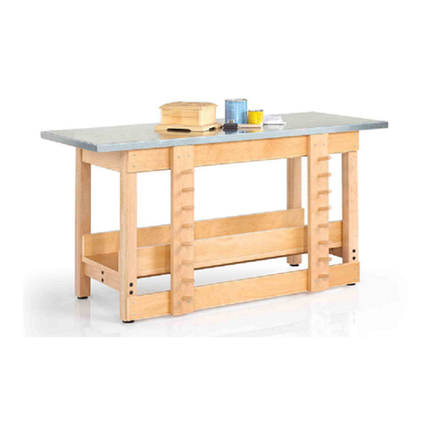
Lista Align Assembly instructions

Align™ Adjustable Height
Workbench
formerly Ergomation EDG workbench
Instructions for Assembly
Motorized Base page 2
Hand-Crank Base page 4
Slide Leg Base page 6
Align 500 page 8
Align™ is a trademark of Lista International Corporation.
Making Workspace Work® is a trademark of Lista International Corporation.
Creation Date Document Number Rev Description
12/29/2004 MD032A3 0 Align Adjustable Height Workbench
This manual is proprietary information of Lista International Corporation. Unauthorized reproduction of any portion of this
manual is prohibited without the written consent of Lista International Corporation. The material in this manual is for
informational purposes only. It is subject to change without notice. Lista International Corporation assumes no responsibility for
any typographical errors contained in this manual.
© 2004 by Lista International Corporation, all rights reserved
106 Lowland Street
Holliston, MA 01746-2094
All rights reserved.
For questions or technical support, call 1-800-722-3020
ISO 9001 Certified

- 2 -
Motorized Base - Center Justified
Tools: 3/16" Hex
Tools: 3/16" Hex
Tools: 3/16" Hex
Tools: 5/32" Hex
7/16" Wrench
Tools: Phillips head screwdriver
Note on Programming Switch:
Move up or down to desired height.
Press “S”, release and press “1”,
repeat for “2”, and “3”
Note: Once programmed, the
number must be “held in” until
programmed height is reached.
STEP 1
a) Attach foot to leg using
(4) 5/16"-18 x 2" bolts.
b) Thread levelers into foot.
c) Repeat to other leg.
STEP 3
a) Attach BRKT2001 to (2)
remaining side bracket
using (2) 5/16"-18 x 5/8"
bolts.
b) Slide one bracket assembly
into each end of rear fixing
frame channel and tighten.
STEP 2
a) Stand frame on feet
b) Attach side bracket to
front of frame using (3)
5/16"-18 x 5/8" bolts.
c
)
Re
p
eat to other end.
STEP 4
a) Attach deck support to side
bracket using (2) 1/4" x 20-
5/8" bolts and (2) 1/4" kep
nuts
b) Repeat to other end
c) Repeat steps a) and b) to
back side of station.
Tools Required
•3/16" Hex
•5/32" Hex
•7/16" Wrench
•Phillips head screwdriver
STEP 5
a) Attach 3-position memory
hand switch to front deck
support with (2) #8-32 x 1/
2" phillips machine bolts and
(
2
)
#8 - 32 ke
p
nuts.
Completed View

- 3 -
Motorized Base - Rear Justified
Completed View
STEP 1
a) Attach foot to leg using (4)
5/16"-18 x 2" bolts.
b) Thread levelers into foot.
c) Repeat to other leg.
Tools: 3/16" Hex
STEP 2
a) Stand frame on feet
b) Attach side bracket using (3)
5/16"-18 x 5/8" bolts.
c) Repeat to other end
Tools: 3/16" Hex
STEP 3
a) Attach front deck support to
side bracket using (2) 1/4"-20 x
5/8" bolts and (2) 1/4"-20 x 5/8"
kep nuts.
b) Repeat to other end
Tools: 5/32" Hex
7/16" Wrench
STEP 4
Attach 3-position memory hand
switch to front deck support with (2)
#8-32 x 1/ 2" Phillips machine bolts
and (2) #8 - 32 kep nuts
Tools: Phillips head screwdriver
Completed View
1,000lb Evenly distributed load
capacity
Note on Programming Switch:
Move up or down to desired height.
Press “S”, release and press “1”,
repeat for “2”, and “3”
Note: Once programmed, the
number must be “held in” until
programmed height is reached
Tools Required
•3/16" Hex
•5/32" Hex
•7/16" Wrench
•Phillips head screwdriver

- 4 -
Hand-Crank Base -Center Justified
Tools: 3/16" Hex
Tools: 3/16" Hex
STEP 3
a) Attach BRKT2001 to (2)
remaining side bracket using (2)
5/16"-18 x 5/8" bolts.
b) Slide one bracket assembly into
each end of the rear fixing frame
channel and tighten.
Tools: 3/16" Hex
Tools: 5/32" Hex
7/16" Wrench
Tools: (2) 7/16" Wrenches
Tools: Hammer
Needle Nose Pliers
Completed View
Tools Required
3/16" Hex
5/32" Hex
(2) 7/16" Wrenches
Hammer
Needle Nose Pliers
STEP 1
a) Attach foot to leg using
(4) 5/16"-18 x 2" bolts.
b) Thread levelers into foot.
c) Repeat to other leg.
STEP 2
a) Attach side bracket using
(3) 5/16"-18 x 5/8" bolts.
b) Repeat to other side.
STEP 4
a) Attach deck support to
side bracket using
(2) 1/4"-20 x 5/ 8" bolts
and (2) 1/4"-20 kep nuts.
b) Repeat to other end.
c) Repeat steps a) and b) to
b
ack side
STEP 5
a) Attach crank bracket to
front deck support using
(2) 1/4"-20 x 1/ 2" bolts
and (2) 1/4"-20 kep nuts.
STEP 6
a) Attach coupling to crank gear
box using a 5/32" roll pin.
b) Slide crankshaft with handle
through the bracket in step 4.
c) Attach crankshaft to coupling
with 5/32" roll pin.

- 5 -
Hand-Crank Base - Rear Justified
Tools: 3/16" Hex
Tools: 3/16" Hex
Tools: 5/32" Hex
7/16" Wrench
Tools: (2) 7/16" Wrenches
Tools: Hammer
Needle Nose Pliers
500 lb. Evenly distributed load
capacity
STEP 1
a) Attach foot to leg
using (4) 5/16"-18 x 2"
bolts.
b) Thread levelers into
foot.
c) Repeat to other leg.
STEP 2
a) Stand Frame on feet.
b) Attach side bracket
using (3) 5/16"-18 x
5/8" bolts.
c) Repeat to other end.
STEP 3
a) Attach front deck support
to side bracket using
(2) 1/4"-20 x 5/ 8" bolts
and (2) 1/4"-20 kep nuts.
b) Repeat to other end.
STEP 5
a) Attach coupling to crank
gear box using a 5/32"
roll pin.
b) Slide crankshaft with
handle through the
bracket in step 4.
c) Attach crankshaft to
coupling with 5/32" roll
p
in.
Completed View
Tools Required
•3/16" Hex
•(2) 7/16" Wrenches
•Hammer
•Needle Nose Pliers
•5/32" Hex
•7/16" Wrench
STEP 4
a) Attach crank bracket to
front deck support
using (2) 1/4"-20 x 1/2"
bolts and (2) 1/4"-20
kep nuts. Completed View

- 6 -
Slide Leg Base - Center Justified
Tools: 3/16" Hex
Tools: 3/16" Hex
Tools: 3/16" Hex
Tools: 3/16" Hex
Tools: 5/32" Hex
7/16" Wrench
Note on Height Adjustment:
•Lift frame to relieve
pressure on adjusting
pins
•(2) men or
lift
Do NOT lift from
work surface
•Remove pins
•Slide to desired height
•Replace pins
STEP 2
a) Attach foot to leg using
(4) 5/16"-18 x 2" bolts.
b) Thread levelers into foot.
c) Repeat to other leg.
STEP 1
a) Attach rear fixing frame
channel to back side of leg
assembly using (8) 5/16"-18 x
5/8"
b
olts.
STEP 3
a) Attach side bracket to front
of frame using (3) 5/16"-18
x 5/8" bolts.
b) Repeat to other end.
Completed View
Tools Required
•3/16" Hex
•5/32" Hex
•7/16" Wrench
STEP 4
a) Attach BRKT2001 to (2)
remaining side bracket
using (2) 5/16"-18 x 5/8"
bolts.
b) Slide one bracket assembly
into each end of the rear
fixing frame channel and
tighten.
STEP 5
a) Attach deck supports to side
bracket using (2) 1/4" x 20-
5/8" bolts and (2) 1/4" kep
nuts
b) Repeat to other end
c) Repeat steps a) and b) to
b
ack side of station.

- 7 -
Slide Leg Base - Rear Justified
STEP 1
a) Attach rear fixing frame
channel to back side of leg
assembly using (8) 5/16"-18 x
5/8" bolts
Tools: 3/16" Hex
STEP 2
a) Attach foot to leg using (4)
5/16"-18 x 2" bolts.
b) Thread levelers into foot.
c) Repeat to other leg.
Tools: 3/16" Hex
STEP 3
a) Stand frame on feet
b) Attach side bracket using
(3) 5/16"-18 x 5/8" bolts.
c) Repeat to other end.
Tools: 3/16" Hex
STEP 4
a) Attach front deck tube to
side bracket using (2) 1/4"-
20 x 5/ 8" and
(2) 1/4"-20 kep nuts.
b) Repeat to other side.
Tools: 5/32" Hex
7/16" Wrench
1,000lb Evenly distributed
load capacity
Note on Height Adjustment:
•Lift frame to relieve
pressure on adjusting
pins
•(2) men or
lift
Do NOT lift from
work surface
•Remove pins
•Slide to desired height
•Replace pins
Tools Required
•3/16" Hex
•5/32"” Hex
•7/16" Wrench Com
p
leted View
Completed View

- 8 -
Align 500 - Rear & Center Justified
STEP 1
a) Attach side bracket using (3)
5/16"-18 x 5/8" bolts
b) Repeat to other leg
Tools: 3/16" Hex
Tools: 3/16" Hex
STEP 3
a) Attach foot to leg using (4) 5/16"-
18 x 2" bolts.
b) Thread levelers into foot.
c) Repeat to other leg.
Tools: 3/16" Hex
STEP 4 (Center Justified Only)
Tools: 3/16" Hex
Tools: ½” Wrench
Note: Work surface sold separately
500 lb Evenly distributed load capacity
Tools Required
•3/16" Hex
•1/2" Wrench
Com
p
leted View
Completed View
a) Attach BRKT2001 to (2)
remaining side brackets
using (2) 5/16”-18 x 5/8"
bolts.
b) Slide bracket assembly into
each end of the rear fixing
frame channel and tighten.
Final Assembly
a) Remove 6 ½” long hex head
bolt & spacer
b) Set leg to desired height
c) Install bolt and spacer and
fully tighten
STEP 2
a) Attach rear fixing frame
channel to back side of leg
assembly using (8) 5/16"-18
x 5/8" bolts
Note: All bolts must be fully
tightened
Popular Tools Storage manuals by other brands
Husky
Husky HPRO72TLOCKERBL Use and care guide

Toggle
Toggle TOGL2448EL Assembly instructions

Craftsman
Craftsman Side Cabinet with SS Protect-it owner's manual

Whittan
Whittan Stockrax T bar Guide to assembly

Cocraft
Cocraft TOOL CHEST Original instructions

Batavia
Batavia CROC LOCK COMPACT CROC LOCK COMPACT operating instructions