Genevac II Series User manual

Artisan Technology Group is your source for quality
new and certied-used/pre-owned equipment
• FAST SHIPPING AND
DELIVERY
• TENS OF THOUSANDS OF
IN-STOCK ITEMS
• EQUIPMENT DEMOS
• HUNDREDS OF
MANUFACTURERS
SUPPORTED
• LEASING/MONTHLY
RENTALS
• ITAR CERTIFIED
SECURE ASSET SOLUTIONS
SERVICE CENTER REPAIRS
Experienced engineers and technicians on staff
at our full-service, in-house repair center
WE BUY USED EQUIPMENT
Sell your excess, underutilized, and idle used equipment
We also offer credit for buy-backs and trade-ins
www.artisantg.com/WeBuyEquipment
REMOTE INSPECTION
Remotely inspect equipment before purchasing with
our interactive website at www.instraview.com
LOOKING FOR MORE INFORMATION?
Visit us on the web at www.artisantg.com for more
information on price quotations, drivers, technical
specications, manuals, and documentation
Contact us: (888) 88-SOURCE | sales@artisantg.com | www.artisantg.com
SM
View
Instra

T
Th
he
e
G
Ge
en
ne
ev
va
ac
c
H
HT
T-
-
8
8
&
&
H
HT
T-
-1
12
2
S
Se
er
ri
ie
es
s
I
II
I
E
Ev
va
ap
po
or
ra
at
ti
io
on
n
S
Sy
ys
st
te
em
ms
s
U
Us
se
er
r
M
Ma
an
nu
ua
al
l
Issue 1-9 – June 2008
Part Number 04-4541
Artisan Technology Group - Quality Instrumentation ... Guaranteed | (888) 88-SOURCE | www.artisantg.com

Artisan Technology Group - Quality Instrumentation ... Guaranteed | (888) 88-SOURCE | www.artisantg.com

Genevac HT-8 & HT-12 Series II Evaporating Systems
04-4541 Issue 1-9 – June 2008 Page 3 of 64
Contents
1Introduction ........................................................................................................................................ 5
Amendment Control Form .................................................................................................................... 6
1.1 Safety symbols ..................................................................................................................................... 6
Genevac Evaporators and Combustible Solvents ............................................................................................. 6
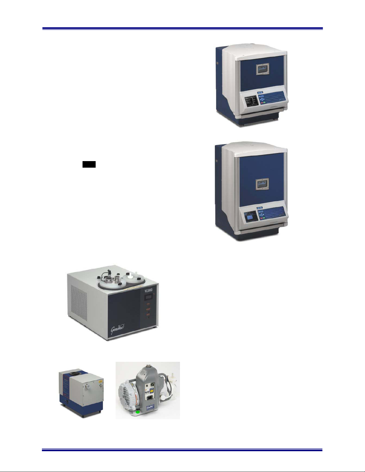
2System description and options ....................................................................................................... 7
3Scope of delivery and installation ..................................................................................................... 8
3.1 Checking the delivery ........................................................................................................................... 8
3.2 Arranging commissioning ..................................................................................................................... 8
3.3 Training ................................................................................................................................................ 8
3.4 Positioning the evaporator .................................................................................................................... 8
3.5 Fitting the vacuum pump ...................................................................................................................... 9
4Safety ................................................................................................................................................ 10
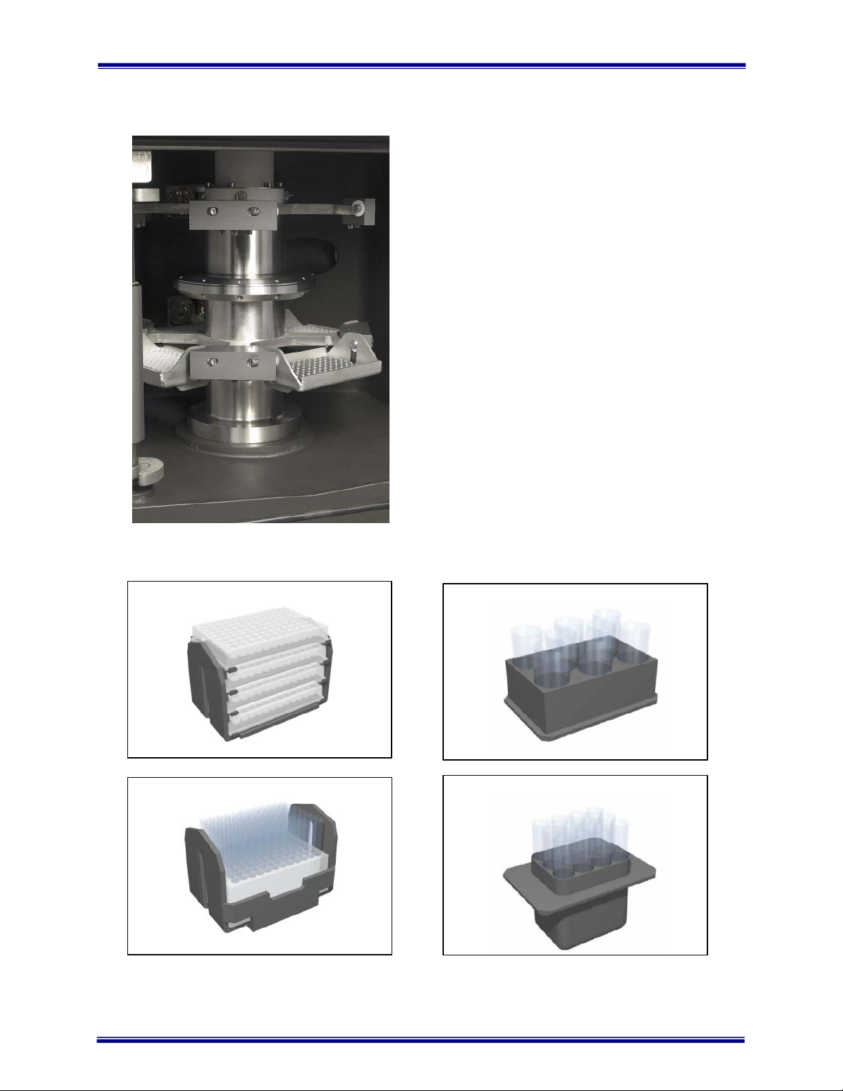
4.1 Safe loading of rotor ........................................................................................................................... 10
4.2 Safe loading of rotor – General Document ......................................................................................... 11
Nomenclature ..................................................................................................................................... 11
Use of Correct Accessories ................................................................................................................ 11
Adherence to Mass Limit .................................................................................................................... 12
Safe loading of sample holders into swings ........................................................................................ 12
Incorrect – Sample Holder rotated ...................................................................................................... 12
Correct – Sample Holder well seated ................................................................................................. 12
Incorrect – Sample Holder on edge of swing ...................................................................................... 12
Series I vs Series II Swings: ............................................................................................................... 13
Balancing of swings and sample holders. ........................................................................................... 13
Good procedural practice ................................................................................................................... 14
4.3 Safe door operation ............................................................................................................................ 15
4.4 Limitations of use ............................................................................................................................... 15
5Getting started .................................................................................................................................. 15
5.1 How to switch on the pump ................................................................................................................ 16
5.2 How to switch on the evaporator ........................................................................................................ 16
5.3 Using the keypad ............................................................................................................................... 17
5.4 What the screens do .......................................................................................................................... 18
Sample Holder Type ........................................................................................................................... 19
Sample Volume .................................................................................................................................. 19
Solvent ............................................................................................................................................... 20
SampleGuard Control Temperature ................................................................................................... 22
SampleGuard Control Channel .......................................................................................................... 22
Coolheat Enable Pressure ................................................................................................................. 22
Chamber Temperature Control ........................................................................................................... 22
Rotor Speed ....................................................................................................................................... 23
Heat-Off Option .................................................................................................................................. 23
During a run ....................................................................................................................................... 24
5.5 How to enter control data ................................................................................................................... 27
5.6 How to use SampleGuard .................................................................................................................. 32
5.7 How to use the condenser .................................................................................................................. 34
5.8 How to start a run ............................................................................................................................... 36
6Getting the best from your system ................................................................................................. 39
6.1 Routine Checks .................................................................................................................................. 39
6.2 Problem prevention ............................................................................................................................ 40
6.3 Optimising a run ................................................................................................................................. 41
6.4 Pre-programmed Runs ....................................................................................................................... 42
Artisan Technology Group - Quality Instrumentation ... Guaranteed | (888) 88-SOURCE | www.artisantg.com

Genevac HT-8 & HT-12 Series II Evaporating Systems
Page 4 of 64 04-4541 Issue 1-9 – June 2008
7Care of your system ......................................................................................................................... 43
7.1 How to clean the chamber .................................................................................................................. 43
7.2 How to change the pump fluid (CVP Only) ......................................................................................... 44
7.3 Maintenance and Service ................................................................................................................... 45
7.4 Additional equipment .......................................................................................................................... 46
7.5 Moving your system ........................................................................................................................... 47
8Fault Finding ..................................................................................................................................... 50
9Technical data ................................................................................................................................... 52
Mechanical data ................................................................................................................................. 52
Condenser ......................................................................................................................................... 52
Vacuum system .................................................................................................................................. 52
Vacuum pump - Scroll ........................................................................................................................ 52
Vacuum pump - CVP .......................................................................................................................... 52
Dimensions ........................................................................................................................................ 52
Operating ........................................................................................................................................... 53
Storage .............................................................................................................................................. 53
10 EC Declaration of Conformity ......................................................................................................... 54
11 Safety ................................................................................................................................................ 54
12 Warranty Statement ......................................................................................................................... 55
13 Annex A ............................................................................................................................................ 56
14 Useful information ............................................................................................................................ 64
These instructions are subject to change without notice.
No part of these instructions may be reproduced in any form or be processed, duplicated or distributed by electronic or optical means
without the written permission of Genevac Limited.
All rights reserved. © Genevac Limited
These operating instructions should be read before you use the Genevac HT-8 & HT-12 Evaporating System.
Keep them near the system for easy reference.
Your attention is drawn in particular to Section 4 Safety.
Artisan Technology Group - Quality Instrumentation ... Guaranteed | (888) 88-SOURCE | www.artisantg.com

Genevac HT-8 & HT-12 Series II Evaporating Systems
04-4541 Issue 1-9 – June 2008 Page 5 of 64
HT-8 Rotor
1 Introduction
The Genevac Series II range of evaporation systems
are state-of-the art and represent a significant step
forward in evaporation technology for the R&D
laboratory.
Drawing on extensive experience in the drug
discovery field, the HT-8 and HT-12 systems are
designed to provide very high performance coupled
with ease of use.
As you will discover, the system is simple to set up,
easy to operate and very flexible.
The status of the system is displayed and controlled
on a single keypad, display module indicating the run
time, the vacuum, rotor temperature and chamber
temperature on digital displays.
Simple to use up-down controls enable the run time,
rotor and chamber temperatures to be set in an
instant and single push buttons set the other
functions.
This manual will guide you through the start up
requirements, set up needs and operation of the
system to facilitate the most efficient procedure to
protect your product’s integrity and to ensure
optimum performance at all times.
Artisan Technology Group - Quality Instrumentation ... Guaranteed | (888) 88-SOURCE | www.artisantg.com

Genevac HT-8 & HT-12 Series II Evaporating Systems
Page 6 of 64 04-4541 Issue 1-9 – June 2008
Amendment Control Form
Revision
Number.
Issue and Reason for Change Date Issued
1 Introduction of Warranty Statement 26 April 2004
2 Changes to Declaration of Conformity. 21 September 2004
3 Additional Technical Information regarding Power Supplies 11 November 2004
4 Information on the correct use of SampleGuard Probes 28 September 2005
5 Introduction of Auto Defrost and Drain Option 19 September 2006
6 Introduction of Annex A – Getting the best from Auto Defrost and Drain 15 September 2006
7 Converted to A5 Booklet 08 December 2006
8 Add Maintenance of Rotor, Swings and Sample Holders 09 April 2008
9 Update page footers 09 June 2008
1.1 Safety symbols
The following safety symbols are used throughout this manual. The definitions and scope of each symbol is
as described below.
WARNING
THIS SYMBOL INDICATES HAZARDS THAT CAN LEAD TO SERIOUS MATERIAL
DAMAGE OR POTENTIAL SERIOUS INJURY.
Caution
This symbol provides information about hazards that can be harmful to your
health or lead to material damage.
Note
This symbol provides information about technical requirements, which if not followed,
can lead to malfunctions, inefficiency and reduced productivity.
This symbol indicates that there may be a risk to sample integrity.
Genevac Evaporators and Combustible Solvents
Please note it remains the responsibility of the user to consider safety when evaporating any combustible
solvents and ensure the system is placed in a well ventilated environment. Genevac's position regarding
evaporation of such solvents, particularly with respect to the European ATEX directive, is available on our
website or from your local sales representative.
IMPORTANT
THIS SYSTEM MUST BE
EARTHED – SEE PAGE 53
Artisan Technology Group - Quality Instrumentation ... Guaranteed | (888) 88-SOURCE | www.artisantg.com

Genevac HT-8 & HT-12 Series II Evaporating Systems
04-4541 Issue 1-9 – June 2008 Page 7 of 64
2 System description and options
Your HT-8 and/or HT-12 Evaporation System is
comprised of an evaporation chamber and rotor, with
an external a cryopump-condenser unit.
Vacuum is provided by the Scroll Pump, although
other types of vacuum pumps can be used.
Solid-state case heaters and Coolheat radiant lamps
heat the chamber and samples.
The control of chamber, bucket and sample
temperature, vacuum ramping rate, chamber
pressure, rotor speed and run time are all handled by
an embedded PC.
The end user has the facility to auto program run
parameters for any (recognised) solvent/mixture
entered. These optimised run parameters are
highlighted in Cyan on the display screen, when this
Auto Program facility has been selected.
Recognised Solvent(s) available from drop down
menu.
Sample Holder type available from drop down menu.
Lyophilisation (Freeze Drying) is available as a Rotor
Speed (Very Low (50g)) selection on evaporators
equipped for this configuration.
Please note: Lyophilisation samples are to be frozen
prior to being placed in evaporator.
HT-8
HT-12
VC3000D Condenser
CVP Pump Scroll Pump
End of Run Prediction:
1 Heat Flow.
2 Sample Detection.
Auto Defrost & Drain is available, providing it was
specified at the time of placing the order.
The Run Progress screen now has a fully featured
graphical display, providing annotated plots for
temperature and pressure (now a log scale).
The control software enables the user to specify and
store a library of up to 100 different evaporation
profiles in an uncomplicated manner.
Run profiles can also be linked to provide multi stage
runs. Up to 100 different profile steps can be linked
and iterative loops can also be programmed.
With a maximum single run time of just below
100 hours, the system is extremely flexible to
meet every requirement.
Artisan Technology Group - Quality Instrumentation ... Guaranteed | (888) 88-SOURCE | www.artisantg.com

Genevac HT-8 & HT-12 Series II Evaporating Systems
Page 8 of 64 04-4541 Issue 1-9 – June 2008
3 Scope of delivery and installation
You will have purchased your system with or without
the option of commissioning by Genevac personnel
and possibly, without the option of a Genevac
vacuum pump and condenser.
Reference will be made in the following notes to the
installation procedures required to cover these
options.
On delivery, it is advisable to unpack your system at
the point of receipt, to ease the movement of the
component parts to the point of use.
3.1 Checking the delivery
Check the contents of the delivery as soon as
possible against the delivery note and notify
Genevac Ltd immediately of any missing or
damaged parts. (Refer to section 10 for contact
details).
3.2 Arranging commissioning
If your system is to be delivered separately, Genevac
Ltd will contact you prior to the delivery, to agree a
date to commission your system.
3.3 Training
Commissioning will normally include training in the
basic operation of the System. Further in house
training is recommended to fully exploit the flexibility
of the system.
THE HT-8/HT-12 EVAPORATOR MUST NOT BE
OPERATED BY PERSONNEL WHO LACK THE
TRAINING OR PROFESSIONAL EXPERIENCE TO
COMPREHEND THE HAZARDS THAT CAN ARISE
WHEN USING THE SYSTEM.
Personnel without such training require thorough
instruction. These operating instructions should form
the basis of this instruction.
3.4 Positioning the evaporator
POSITION THE EVAPORATOR AT LEAST 300 MM
AWAY FROM THE EDGE OF A BENCH AND THE
SAME DISTANCE CLEAR OF BREAKABLE
OBJECTS OR AREAS WHERE ENTRAPMENT
COULD OCCUR.
Artisan Technology Group - Quality Instrumentation ... Guaranteed | (888) 88-SOURCE | www.artisantg.com

Genevac HT-8 & HT-12 Series II Evaporating Systems
04-4541 Issue 1-9 – June 2008 Page 9 of 64
IF THIS POSITIONING REQUIREMENT IS
IMPRACTICAL THEN THE EVAPORATOR
SHOULD BE BOLTED TO THE BENCH OR
TROLLEY, BY ITS FIVE MOUNTING FEET, USING
M10 H.T. BOLTS ZINC.
GENEVAC SHOULD BE CONSULTED FOR
ADVISE ON ANY OTHER POSITIONAL
REQUIREMENTS.
3.5 Fitting the vacuum
pump
One of the following pumps will
have been supplied with your
system:
Scroll:
The Scroll pump supplied by
Genevac is only available as a
Non Recirculating model.
CVP:
The CVP 100 pump as
previously supplied by Genevac
was available in two formats:
the standard (Non
Recirculating) model or the
optional Recirculating model.
General
The Genevac pump supplied
with your evaporator will have
the connecting pipe/pipes,
fittings and power control lead
included with it.
Connect your vacuum pump to
the evaporator using the
connecting pipe and flange
fittings.
Connect the power and control
lead between the pump and the
socket on the rear of the
chamber.
If your system has been supplied with a Scroll pump then it must not be moved
between systems without first consulting Genevac Service for advise.
The Scroll pump will only function correctly on a Genevac Evaporator that has
been upgraded to work with the Scroll pump.
If your system has been supplied with a CVP pump then it must have an adequate supply of cooling
air and the hot outlet must have at least 300 mm of space beyond the hot air grille in the pump base.
It should not be placed in a cupboard without special precautions to ensure adequate cooling.
Consult Genevac Service for advice in such cases.
Artisan Technology Group - Quality Instrumentation ... Guaranteed | (888) 88-SOURCE | www.artisantg.com

Genevac HT-8 & HT-12 Series II Evaporating Systems
Page 10 of 64 04-4541 Issue 1-9 – June 2008
•There are important safety
and operational
considerations to be made
when positioning the
system.
•Refer to Section 9
Technical Data for
recommended clearances
4 Safety
BEFORE OPERATING THE SYSTEM, IT IS
IMPORTANT THAT THE FOLLOWING NOTES ARE
READ TO ENSURE THAT THE IMPLICATIONS TO
THE SAFETY OF PERSONNEL OPERATING THE
SYSTEM AND FOR THE PROTECTION OF SAMPLE
INTEGRITY ARE UNDERSTOOD.
Samples in the chamber are subjected to
accelerations of up to 500G with a maximum load
capacity of 1.5 kg per swing.
The following precautions should therefore always be
observed.
4.1 Safe loading of rotor
Never exceed the maximum load capacity of 1.5 kg
per swing.
Balance pairs of sample holders that are loaded
opposite each other to within 10g (approximately).
Locate tubes correctly in tube holders.
Locate sample blocks correctly in sample swings.
Load two or four tube holders in opposite and
balanced configurations.
Distribute tubes in sample holders symmetrically.
Rotate the rotor by hand after loading and check that
all tube holders and plates are correctly located before
starting a run and before re-starting an interrupted run.
Do not load tubes or vials into sample holders other
than those types that have been approved by
Genevac Ltd.
Do not use sample holders that have not been
supplied with system without consulting Genevac
Service.
Refer to SampleGuard - Probe Positions document
available at:
http://www.genevac.com/applications/downloads1.html
for correct use of Sample Guard Probes.
1.5 kg MAX including tubes, solvent,
sam
p
le, sam
p
le holder and swin
g
Genevac Ltd will accept no
responsibility for any loss or damage
incurred by improperly or excessively
loaded rotors.
Artisan Technology Group - Quality Instrumentation ... Guaranteed | (888) 88-SOURCE | www.artisantg.com

Genevac HT-8 & HT-12 Series II Evaporating Systems
04-4541 Issue 1-9 – June 2008 Page 11 of 64
4.2 Safe loading of rotor – General Document
Genevac are obliged to include the following information in its entirety, irrespective of the system type.
As with a centrifuge, a Genevac centrifugal evaporator must be loaded correctly to remove risk of damage.
Failure to correctly load a system can lead to loss of samples, system damage and significant downtime. This
guide is intended for new users and also as a reminder for more experienced users. The principles outlined
apply to all Genevac evaporators.
The document deals with various aspects of loading:
•Use of correct swings and sample holders
•Observation of weight limits
•Safe loading of sample holders into swings
•Balancing of swings and sample holders
•Good procedural practice
Nomenclature
Firstly, it is important to understand what is meant by some of the terms that will be used in this document.
Most Genevac systems feature “swung” rotors.
(Some, however, feature “fixed” rotors, with many angled holes for individual tubes. But this document
however is primarily concerned with swung rotors).
A swung rotor includes a swing or bucket. Below are drawings of typical swings for HT systems.
Open (or standard) Side-Bridge Fast-StackTM
(for microtitre plates)
Each of these swing types lifts straight out of the rotor. On large Mega systems, however (not shown here) the
swings are generally fixed in place and cannot be lifted out. Which swing is ideal depends on which sample
holder is required.
There is a large range of sample holders which sit in the swings, into which tubes, vials, beakers or flasks are
loaded.
Use of Correct Accessories
Genevac supply a wide range of sample holders to cover a variety of plate, tube, vial or flask formats. Where
no holder is available, custom units can be made. In a few cases worldwide, users have developed their own
holders and have collaborated with the Genevac R&D department to ensure the holders are suitable and
approved for use.
Important properties for a sample holder include:
•Mass within prescribed maximum limit.
•Closely matched mass within a set of holders.
•Correct centre of gravity.
•Good thermal conductivity.
•Correct hole form and size tolerance to prevent tube or vial breakage under centrifugal force.
All Genevac holders are designed with these constraints in mind. Other 3rd party accessories may not be.
Generally, apart from microtitre plates, users are advised not to load non-Genevac holders into a system
without first checking with Genevac.
It is important that the swings and holders used are suitable for the Genevac system in use. For example,
there are some sample holders on sale for the Series II system that might appear to fit in a Series I system but
which would exceed the weight limitations. (See next section). If in doubt always ask Genevac before running
the system.
Artisan Technology Group - Quality Instrumentation ... Guaranteed | (888) 88-SOURCE | www.artisantg.com

Genevac HT-8 & HT-12 Series II Evaporating Systems
Page 12 of 64 04-4541 Issue 1-9 – June 2008
There are also instances where a sample holder which is perfectly satisfactory (for the tube or vial it is intended
for) becomes unsuitable if used with something else, even though it might appear that the alternative tube fits
O.K. The Genevac Accessories Brochure indicates for each holder the maximum tube length that the holder is
designed to take, and these limits should always be adhered to. (It is available from the website,
http://www.genevac.com/brochure/GenevacAccessories.pdf)
Similarly some sample holders are intended for use in a Side-Bridge swing only, not in an Open swing, even
though they might appear to fit in the latter. The Accessories Brochure has a note “For use in Side-Bridge
Swing” by these items, but if in doubt, ask Genevac.
Some users wish to run Genevac systems using the “Bohdan Miniblock” system as their sample holder. Please
note, some (not all) of this range of items significantly exceed the mass limitations of a Genevac system. If you
plan to use Bohdan Miniblocks in a Genevac system, please contact Genevac for a list of the relevant weights.
Adherence to Mass Limit
There is a maximum mass that can be loaded onto each position of a Genevac swung rotor, this total includes:
•The swing
•The sample holder
•The tubes or vials
•The sample solutions
Under no circumstances should this be exceeded.
If in doubt what your combined mass total is, load up a full swing and weigh it.
In most cases, with normal solvent volumes, any sample holder currently on sale from Genevac will fall within
the mass limit for a Series II system.
Safe loading of sample holders into swings
Applicable where both Series I and Series II evaporators are being used within the same laboratory.
There are two ways that it is possible to misload a sample holder into a swing.
One (shown below) is to rotate the sample holder such that it rests on the edges of the swing.
Incorrect – Sample Holder rotated
Correct – Sample Holder well seated
Another mode of misloading is illustrated below.
Incorrect – Sample Holder on edge of swing
Correct
Both these modes of misloading are possible with an older version of the Open or standard swing but are
virtually impossible with the new design of swing, all Series II systems feature the new design of swing. The
following illustration shows the difference.
Artisan Technology Group - Quality Instrumentation ... Guaranteed | (888) 88-SOURCE | www.artisantg.com

Genevac HT-8 & HT-12 Series II Evaporating Systems
04-4541 Issue 1-9 – June 2008 Page 13 of 64
Series I vs Series II Swings:
The older Series I design is easy to distinguish
because the corners are not welded.
The newer (“Series II“) swing has angled sides
that make the incorrect loading illustrated
above virtually impossible. Care still has to be
taken though.
It also has rounded and welded corners.
Genevac offer a low cost upgrade to any user who has the old type of swing and who wishes to avoid the
possibility of this misloading ever occurring
Balancing of swings and sample holders.
Opposite pairs of swings need to be balanced within specification and that the swings are of the same type and
version. Please note that there are several versions of Side Bridge Swings in circulation with a static weight
ranging from 375g to 445g. Ensure that swings of the same static weight are positioned diametrically opposite
in the rotor; ideally use the same version of swings in all four position of each rotor. Genevac systems have
some inbuilt tolerance for imbalance and a system for shutting off if the out-of- balance is unacceptably high but
it is advised that the user aims for no more than 10g imbalance between opposite pairs of swings.
Where it is necessary to make “dummy” samples to balance real loads, the balancing load should be of a
similar solvent composition. For example, do not balance 200g of 50/50 Water/Acetonitrile with 200g of water,
because partway through the run, when the acetonitrile has all gone but the water has barely started
evaporating, the system would be 100g imbalanced.
Note that with a system such as the Fast-StackTM swing, balancing is slightly more complex. Suppose a “Fast-
StackTM Deepwell” swing is used with two 96 well microtitre plates, 2ml per well. (The Fast-StackTM swing is
illustrated on the first page of this document). In one swing, the lower microtitre plate is empty, the upper
microtitre plate is full, 1.8mls per well. On the other swing, the reverse is true.
The two swings now weigh the same, but if
placed opposite each other in a system, would
not be balanced, because when the swings
rotated to their operating attitude, the centre
of mass of one is at a different radius to that
of the other.
This effect becomes very significant when balancing multi level swings in large Mega systems.
It is also preferable not to run with only two swings out of four present on any one level of the rotor. If there are
only two swings’ worth of samples, you should still load swings and empty sample holders in the other
positions. This ensures the rotor is evenly loaded.
Artisan Technology Group - Quality Instrumentation ... Guaranteed | (888) 88-SOURCE | www.artisantg.com

Genevac HT-8 & HT-12 Series II Evaporating Systems
Page 14 of 64 04-4541 Issue 1-9 – June 2008
Good procedural practice
Finally, there are a few general rules for safe operation of a system:
•Ensure only users familiar with all the issues outlined in this document are permitted to operate the
equipment.
•Only load swings and sample holders approved by Genevac.
•System should be loaded and started by the same person.
•Never leave system unevenly loaded and close the door. Someone may start it.
•Never start, or restart a system without checking it is evenly loaded, all sample holders are correctly seated,
all swings are swinging freely.
•Refer to SampleGuard - Probe Positions document available at:
http://www.genevac.com/applications/downloads1.html
for correct use of Sample Guard Probes.
Misloading may result in damage to samples and the machine, and could void the warranty.
Artisan Technology Group - Quality Instrumentation ... Guaranteed | (888) 88-SOURCE | www.artisantg.com

Genevac HT-8 & HT-12 Series II Evaporating Systems
04-4541 Issue 1-9 – June 2008 Page 15 of 64
4.3 Safe door operation
The door is opened and closed manually but locked
automatically by an electric actuator.
Close and hold the door firmly against the door seal
and press and hold the Door Close switch.
A single audible beep indicates that the door is
locked and it is safe to proceed.
A proximity switch will prevent the mechanism from
locking if the door is not closed.
Hold the door firmly against the door seal whilst
holding down the Close Door switch.
Note that the door mechanism will NOT work if the
condenser is not connected to the system.
4.4 Limitations of use
Your HT-8/HT-12 Series II evaporating system is
unsuitable for use under the following
circumstances.
•With strong mineral acids such as HCl and HBr
at all concentrations, unless specifically built to
order.
•EVAPORATING DIETHYL ETHER AND
OTHER SIMILAR LOW FLASH POINT
SOLVENTS WITHOUT A GENEVAC INERT
PURGE FITTED TO THE EVAPORATOR AND
PUMP.
For use as a pressure vessel.
5 Getting started
The following notes describe the basic start up, set
up and run instructions for your HT-8/HT-12
evaporating system.
When the Genevac vacuum pump is fitted, the
chamber is powered from the pump and so it is only
necessary to connect the pump to a suitable mains
power supply.
Artisan Technology Group - Quality Instrumentation ... Guaranteed | (888) 88-SOURCE | www.artisantg.com

Genevac HT-8 & HT-12 Series II Evaporating Systems
Page 16 of 64 04-4541 Issue 1-9 – June 2008
Scroll
CVP
5.1 How to switch on the pump
Connect the pump to the mains and switch on the
mains.
Switch the pump mains switch on.
The pump will not be ready for use until the green
ready light on the front panel is illuminated (Approx 7
minutes) – but power is available to the evaporator.
The system will not be available for use until the
vacuum pump has reached the correct operating
temperature (about 25 – 30 minutes for the Scroll
pump. This only occurs when the system is first
switched on or when the Auto Stop function has
been used), (5 – 10 minutes for the CVP).
5.2 How to switch on the evaporator
Switch the mains switch on.
The screen will display the Software Control
screen.
Press the START key on the keyboard to access the
Select Run screen.
The Select Run screen will load up at the last run
that was used.
A series of runs have been preloaded from RUN
51 to RUN 100 inclusive.
Runs 51 to 98 provide a range of Standard
Configurations.
Runs 99 and 100 are only for use by engineers for
Maintenance/Diagnostics.
The condenser will be powered up when the
chamber is switched on.
There will be a slight delay until the condenser
reaches the correct temperature.
Artisan Technology Group - Quality Instrumentation ... Guaranteed | (888) 88-SOURCE | www.artisantg.com

Genevac HT-8 & HT-12 Series II Evaporating Systems
04-4541 Issue 1-9 – June 2008 Page 17 of 64
MENU
DISPLAY
SETTINGS
5.3 Using the keypad
The Series II keyboard controls and displays have
been designed for ease and simplicity in use.
The keyboard has the most used function keys on
the left hand side.
The right side illuminates when the RUN DATA
screen is accessed.
The START and STOP keys start and stop a
selected run.
The cursor direction keys move you around the
screen in the direction of the arrows.
The ENTER key is used to ‘open’ and ’close’ a field
on the Run Data screen when inputting or amending
data.
Note that the START key also acts as an ENTER
key when the keyboard is not illuminated.
Operating the MENU key displays the USER MENU
screen only when the rotor is not spinning and the
chamber is vented.
Operating the DISPLAY key displays the RUN LOG
screen only when a run is in progress or has
finished.
Operating the SETTINGS key displays the RUN
DATA screen only for the selected run.
Note that the RUN DATA screen can also be
accessed from the menu VIEW/EDIT DETAILS
option on the SELECT RUN screen when a run is
not in progress.
The following notes describe the function of each of
each screen and provides an explanation of the
prompts displayed.
Artisan Technology Group - Quality Instrumentation ... Guaranteed | (888) 88-SOURCE | www.artisantg.com

Genevac HT-8 & HT-12 Series II Evaporating Systems
Page 18 of 64 04-4541 Issue 1-9 – June 2008
5.4 What the screens do
There are three main control screens.
The SELECT RUN screen lists the library of
evaporation profiles you can choose.
This screen has the capacity to store 100 different
profiles, from which you can select a particular run or
set of runs.
The screen is accessed after switching on the pump
and evaporator and by pressing the START key on
the keyboard.
•You store and select
your runs on these
screens.
•Use the UP and
DOWN cursor keys
to move between
profiles.
By moving across the
horizontal menu bar,
•You can START a
run.
•You can VIEW and
EDIT a profile.
•You can CLEAR a
profile.
•You can COPY a
profile.
•Start to DRAIN.
•Start to DEFROST.
•Start to FLUSH.
(If Option Fitted)
•Adjust your
OPTIONS.
The 100 profiles are shown on this and nine other
screens.
The other screens can be accessed quickly by
moving the cursor down to the last entry on the page
and pressing the down cursor key.
This will take you to the last entry on the next page.
Alternatively, use the up cursor key.
Artisan Technology Group - Quality Instrumentation ... Guaranteed | (888) 88-SOURCE | www.artisantg.com

Genevac HT-8 & HT-12 Series II Evaporating Systems
04-4541 Issue 1-9 – June 2008 Page 19 of 64
SETTINGS
Each line on the SELECT RUN screen is generated
from the RUN DATA screen.
When the chamber is vented and the rotor stationary,
this screen is accessed by selecting VIEW/EDIT at the
foot of the SELECT RUN screen and pressing START.
When the system is running, the RUN DATA screen
can be accessed directly by pressing the SETTINGS
key.
•Use the UP and
DOWN cursor keys
to move between
fields.
•Press ENTER to
‘open’ a field, make
the entry and press
ENTER again to
‘close’ the field.
•During a run, you
access this screen
by pressing the
SETTINGS key.
•You can edit any
parameter during a
run in this way.
•Toggle Run Data
Locked to protect
your data.
Please note that Main Menu order has changed.
It now reads: Sample Holder Type, Sample Volum
e
Solvent
Sample Holder Type
•When selected you
are presented with
the SAMPLE
HOLDER menu.
•Use Cursor keys to
move up and down.
•Press ENTER to
select.
•Select your sample
holder type or if not
defined, select
Other and enter
the details.
Sample Volume
•Select and enter
value(s).
Artisan Technology Group - Quality Instrumentation ... Guaranteed | (888) 88-SOURCE | www.artisantg.com
This manual suits for next models
2
Table of contents
Other Genevac Laboratory Equipment manuals

Genevac
Genevac Rocket 4D User manual

Genevac
Genevac 04-6682 User manual

Genevac
Genevac HT-24 User manual

Genevac
Genevac EZ-2 Elite User instructions

Genevac
Genevac HT-8SII User manual

Genevac
Genevac HT-4X User manual

Genevac
Genevac HT Series User manual

Genevac
Genevac EZ-2 Elite User manual

Genevac
Genevac EZ-2 Series User manual

Genevac
Genevac EZ-2 Series User instructions