Operator's Manual Supplement First Edition • First Printing
Introduction
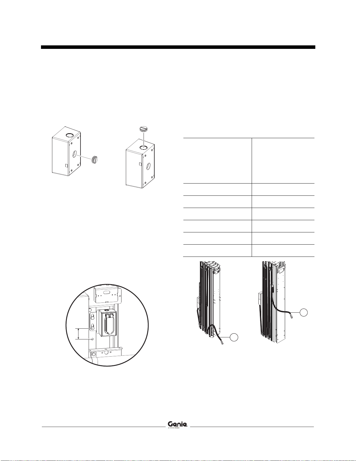
8 Lift Guard™ Contact Alarm Part No. 1293402GT
Contents of Kit 1294049GT
GR-15 (ANSI / CSA)
Description Genie part
number Qty.
Cable tie, 11.5 inch / 29 cm 28443GT 20
Harness, GR-15 mast, ANSI 1293395GT 1
Harness, platform contact alarm 1293397GT 1
Squeeze connector, 1/2 NPT, .45-.71 1293399GT 1
Assembly, contact alarm 1287673GT 1
Wire assembly, contact alarm jumper 1294071GT 1
Manual, Supplement 1293402GT 1
Contents of Kit 1294050GT
GR-20 (CE / AS)
Description Genie part
number Qty.
Cable tie, 11.5 inch / 29 cm 28443GT 20
Harness, GR-20 mast, CE 1293392GT 1
Harness, platform contact alarm 1293397GT 1
Squeeze connector, 1/2 NPT, .45-.71 1293399GT 1
Assembly, contact alarm 1287673GT 1
Wire assembly, contact alarm jumper 1294071GT 1
Manual, Supplement 1293402GT 1
Contents of Kit 1294051GT
GR-20 (ANSI / CSA)
Description Genie part
number Qty.
Cable tie, 11.5 inch / 29 cm 28443GT 20
Harness, GR-20 mast, ANSI 1293396GT 1
Harness, platform contact alarm 1293397GT 1
Squeeze connector 1293399GT 1
Assembly, contact alarm 1287673GT 1
Wire assembly, contact alarm jumper 1294071GT 1
Manual, Supplement 1293402GT 1
Contents of Kit 1294052GT
GRC-12
Description Genie part
number Qty.
Wire, 18 GA, white, GXL 1541GT 3 in
Female terminal, butt seam, 16/14 13826GT 3
Cable tie, 11.5 inch / 29 cm 28443GT 20
Wire assembly, GRC-12 137736GT 1
Harness, platform contact alarm 1293398GT 1
Assembly, contact alarm 1287673GT 1
Wire assembly, contact alarm 1294071GT 1
Manual, Supplement 1293402GT 1