Gentex Smarter Vision HD135 Series User manual

135°F FIXED TEMPERATURE HEAT ALARM,
AC POWERED WITH BATTERY BACKUP
Installation Instructions - Owner's Information READ CAREFULLY AND SAVE
INTRODUCTION HD135
The D135 Series heat alarm is for use as an evacuation device in
residential applications. Each alarm has a solid state piezo that emits a
temporal 3 signal to warn and alert the household to the presence of
threatening heat.
Your heat alarm is designed to detect heat that results from an actual fire.
eat alarms are intended for use as added protection to smoke alarms. This
unit cannot detect smoke or other toxic gases, therefore, do not rely solely on
this heat alarm to provide warning of a fire.
BASIC SAFETY INFORMATION
Dangers, Warnings, Cautions and Notices alert you to important operating
procedures or to potentially hazardous situations. Pay special attention to
these items.
This heat alarm is listed for use in single-family and multi-family
residences, along with hotels, motels and other commercial residential
occupancies.
NEVER ignore your heat alarm if it sounds. Failure to do so can result in
serious injury or death.
Test this device once a week per manufacturer installation recommendation.
If the device ever fails to test correctly, replace immediately! If the device is
not working properly, it can not alert you to a problem.
This product is intended for use in indoor locations.
MODELS
(SEE BACK OF EAT ALARM FOR EXACT MODEL)
** D135......................................................120VAC, 60 z with Temporal 3 orn
* D135-220.............................................................................220VAC, 50/60 z
** D135-223.........................................220VAC, 50/60 z with Temporal 3 orn
* These units produce a non-temporal audible alarm and are therefore not
intended for locations where the desired action of the occupant(s) is
evacuation.
** Per NFPA 72, the American National Standard Audible Emergency Evacuation
Signal as defined in ANSI S3.41, is required whenever the intended response is
to evacuate the building.
NOTICE: IN T E EVENT AC POWER FAILS, A 9VDC BATTERY WILL
PROVIDE PROPER ALARM OPERATION FOR A MINIMUM OF A 24- OUR
PERIOD.
ELECTRICAL SPECIFICATIONS
OPERATING VOLTAGE................................................................120VAC, 60 z
OPERATING CURRENT (MAX.) (120VAC/9VDC).............................0.035 amps
OPERATING VOLTAGE...........................................................220VAC, 50/60 z
OPERATING CURRENT (MAX.) (220VAC/9VDC).............................0.035 amps
OPERATING AMBIENT TEMPERATURE RANGE.........................40OF to 100OF
ALARM ORN RATING................................meets or exceeds 85dBA at 10 feet
MUST USE DURACELL®MN 1604 BATTERY
HOW TO TELL IF YOUR HEAT ALARM IS WOR ING
PROPERLY
Your heat alarm is provided with an alarm horn and pulsating Light Emitting
(indicator) Diode, which pulses every 30 seconds and a green AC power on
LED.
If the battery is low or missing, a chirp will be emitted when the red LED
flashes. If the heat alarm is malfunctioning, the chirp is sounded without the
red LED flashing. If AC power fails, the green LED will turn off.
To test your heat alarm, direct a hair dryer at the sensor element (silver
disk) at a 4-6" distance. Alternatively, a cordless soldering iron may be
applied to the sensor element. The unit will return to normal standby mode
once the disk cools down. A cold damp rag or sponge may be used to
quickly cool the sensor.
NOTE: Tandem Interconnect Models.
When testing one heat alarm, the heat alarm that is activated will flash the
red indicator light and sound its alarm horn. All other units will sound the
alarm horn with their red indicator lights remaining off. The relays will also
activate on all units in tandem on models equipped with the relay option.
FIRE PROTECTION PLAN: WHAT YOU CAN DO TO MA E
YOUR FAMILY SAFE FROM FIRES
Please note that there are hazards against which heat detection may not
be effective, such as smoking in bed, explosions, when a closed door sepa-
rates the heat alarm from the source of the fire, etc. The ultimate responsibility
for fire protection rests solely on you.
Installing heat alarms is just the first step in protecting your family from fires.
You also must reduce the chances that fires will start in your home and
increase your chances of safely escaping if one does start. To have an
effective fire safety program:
a. Install smoke and heat alarms properly following the instructions in
this manual. eep your units clean. Test your alarm weekly and have
unit repaired or replace alarm when it when it no longer functions. As
with any electronic product, smoke and heat alarms have a limited life, and
devices that don't work cannot protect you.
b. Follow safety rules and prevent hazardous situations:
Use smoking materials properly; never smoke in bed.
Keep matches and cigarette lighters away from children.
Store flammable materials in proper containers and never use them near
open flames or sparks.
Keep electrical appliances and cords in good working order and do not
overload electrical circuits.
Keep stoves, fireplaces, chimneys, and barbecue grills grease-free and
make sure they are properly installed away from combustible materials.
Keep portable heaters and open flames such as candles away from
combustible materials.
Do not allow rubbish to accumulate.
Do not leave small children home alone.
c. Develop a family escape plan and practice it with your entire family,
especially small children.
Draw and post a floor plan of your home and find two ways to exit from
each room. There should be one way to get out of each bedroom
without opening the door.
Teach children what the smoke and heat alarm signal means, and that
they must be prepared to leave the residence by themselves if
necessary. Show them how to check to see if doors are hot before
opening them, how to stay close to the floor and crawl if necessary, and
how to use the alternate exit if the door is hot and should not be opened.
Decide on a meeting place a safe distance from your house and make
sure that all your children understand that they should go and wait for
you if there is a fire.
old fire drills at least every 6 months to make sure that everyone, even
small children, know what to do to escape safely.
Know where to go to call the fire department from outside your residence.
Provide emergency equipment such as fire extinguishers and teach your
family to use this equipment properly.
HD135
SERIES
550-0158
Pg. D-1

Association recommends that the alarms be interconnected so that an alarm
on any level of the residence will sound an alarm loud enough to awaken
sleepers in closed bedrooms. This can be done by employing a systematic
approach by interconnecting a fire-detection system, by connecting units
together, or by using radio frequency transmitters and receivers.
All types of smoke and heat alarm sensors have limitations. No type
of smoke or heat alarm can sense every kind of fire every time. In
general, alarms may not always warn you about fires caused by violent
explosions, escaping gas, improper storage of flammable materials, or
arson. These types of fires include:
1) Fires where the victim is intimate with a flaming initiated fire; for
example, when a person’s clothes catch on fire while cooking.
2) Fires where the smoke and/or heat is prevented from reaching the
smoke or heat alarm due to a closed door or other obstruction.
3) Incendiary fires where the fire grows so rapidly that an occupant’s
egress is blocked even with properly located smoke alarms and heat
alarms.
NOTICE: T IS EAT ALARM IS NOT DESIGNED TO REPLACE SPECIAL-
PURPOSE FIRE DETECTION AND ALARM SYSTEMS NECESSARY TO
PROTECT PERSONS AND PROPERTY IN NON-RESIDENTIAL BUILDINGS
SUC AS WARE OUSES, OR OT ER LARGE INDUSTRIAL OR
COMMERCIAL BUILDINGS. IT ALONE IS NOT A SUITABLE SUBSTITUTE
FOR COMPLETE FIRE-DETECTION SYSTEMS DESIGNED TO PROTECT
INDIVIDUALS IN OTELS AND MOTELS, DORMITORIES, OSPITALS, OR
OT ER EALT AND SUPERVISORY CARE AND RETIREMENT OMES.
PLEASE REFER TO NFPA 101,T E LIFE SAFETY CODE, AND NFPA 72
FOR SMOKE ALARM REQUIREMENTS FOR FIRE PROTECTION IN
BUILDINGS NOT DEFINED AS " OUSE OLDS."
NOTICE: T IS DEVICE WILL NOT SOUND FOR A CARBON MONOXIDE
(CO) EVENT W EN TANDEM INTERCONNECTED TO A GENTEX CO OR
SMOKE/CO ALARM.
Installing smoke and heat alarms may make you eligible for lower
insurance rates, but smoke alarms and heat alarms are not a substitute for
insurance. omeowners and renters should continue to insure their lives and
property.
HEAT DETECTION
General - NFPA 72 does not require heat alarms as part of the basic
protection scheme, it is recommended that the householder consider the use of
additional heat alarms for the same reasons presented in the next section.
The additional areas lending themselves to protection with heat alarms are the
dining room, attic (finished or unfinished), furnace room, utility room, basement
and integral or attached garage. For bedrooms, the installation of a smoke
alarm is recommended over the installation of a heat alarm for protection of the
occupants from fires in their bedrooms.
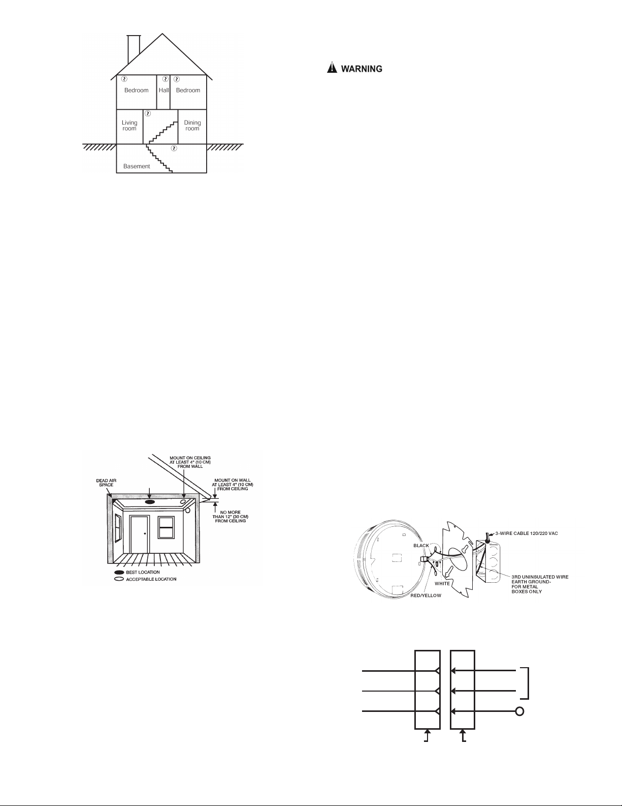
Heat Alar Mounting - Dead Air Space. eat from a fire rises to the
ceiling, spreads out across the ceiling surface, and begins to bank down from
the ceiling. The corner where the ceiling and the wall meet is an air space into
which heat has difficulty penetrating. In most fires, this dead air space
measures about 4 inches (0.1 meter) down the wall as shown in FIGURE 6.
eat alarms should not be placed in this dead air space.
The placement of the heat alarm is critical where maximum speed of fire
detection is desired. Thus, a logical location for a heat alarm is the center of
the ceiling. At this location, the alarm is closest to all areas of the room.
If the heat alarm cannot be located in the center of the ceiling, an
off-center location on the ceiling may be permitted to be used.
Per NFPA 72, 2010 29.8.4.3 eat alarms shall be mounted on the ceiling at
least 4 inches (100mm) from a wall or on a wall with the top of the alarm not
less than 4 inches (100mm), no more than 12 inches (300 mm), below the
ceiling.
The Spacing of Heat Alar s. Where a room is too large for protection by a
single heat alarm (50 ft. spacing), several heat alarms should be used. It is
important that they be properly located so all parts of the room are covered.
Where the Distance Between Heat Alar s Should Be Further Reduced.
The distance between heat alarms is based on data obtained from the spread
of heat across a smooth ceiling. Where the ceiling is not smooth, the
placement of the heat alarm should be tailored to the situation.
For instance, with open wood joists, heat travels freely down the joist
channels so that the maximum distance between alarms, 50 ft. (15 m), may be
permitted to be used. owever, heat has trouble spreading across the joists,
so the distance in this direction should be ½ the distance allowed between
d. Bedroom doors should be closed while sleeping if a smoke or heat
alarm is installed in the bedroom. They act as a barrier against heat and
smoke.
WHAT TO DO IF THERE IS A FIRE IN YOUR HOME
If you have prepared family escape plans and practiced them with your
family, you have increased their chances of escaping safely. Review the
following rules with your children when you have fire drills so everyone will
remember them in a real fire emergency:
a. Don't panic; stay calm. Your safe escape may depend on thinking clearly
and remembering what you have practiced.
b. Get out of the house following a planned escape route as quickly as
possible. Do not stop to collect anything or to get dressed.
c. Open doors carefully only after feeling to see if they are hot. Do not open a
door if it is hot; use an alternate escape route.
d. Stay close to the floor; smoke and hot gases rise.
e. Cover your nose and mouth with a cloth, wet if possible, and take short,
shallow breaths.
f. Keep doors and windows closed unless you open them to escape.
g. Meet at your prearranged meeting place after leaving the house.
h. Call the Fire Department as soon as possible from outside your house.
Give the address and your name.
i. Never re-enter a burning building.
Contact your local Fire Department for more information on making your
home safer from fires and about preparing your family's escape plans.
NOTICE: CURRENT STUDIES AVE S OWN SMOKE ALARMS AND EAT
ALARMS MAY NOT AWAKEN ALL SLEEPING INDIVIDUALS, AND T AT IT IS
T E RESPONSIBILITY OF INDIVIDUALS IN T E OUSE OLD T AT ARE
CAPABLE OF ASSISTING OT ERS TO PROVIDE ASSISTANCE TO T OSE
W O MAY NOT BE AWAKENED BY T E ALARM SOUND, OR TO T OSE
W O MAY BE INCAPABLE OF SAFELY EVACUATING T E AREA
UNASSISTED.
WHAT THIS HEAT ALARM CAN DO
This heat alarm is designed to sense heat produced by a fire.
IT WILL NOT SENSE SMO E OR OTHER TOXIC GASES.
When properly located, installed, and maintained, this heat alarm is
designed to provide warning of developing fires at a reasonable cost. This
alarm monitors the air and, when it senses heat, activates its built-in alarm
horn.
NOTICE: T IS EAT ALARM IS DESIGNED FOR USE WIT IN SINGLE
RESIDENTIAL LIVING UNITS ONLY; T AT IS, IT S OULD BE USED INSIDE
A SINGLE-FAMILY OME OR ONE APARTMENT OF A MULTI-FAMILY
BUILDING. IN A MULTI-FAMILY BUILDING, T E UNIT MAY NOT PROVIDE
EARLY WARNING FOR RESIDENTS IF IT IS PLACED OUTSIDE OF T E
RESIDENTIAL UNITS, SUC AS ON OUTSIDE PORC ES, IN CORRIDORS,
LOBBIES, BASEMENTS, OR IN OT ER APARTMENTS. IN MULTI-FAMILY
BUILDINGS, EAC RESIDENTIAL UNIT S OULD AVE ALARMS TO ALERT
T E RESIDENTS OF T AT UNIT. UNITS DESIGNED TO BE
INTERCONNECTED S OULD BE INTERCONNECTED WIT IN ONE FAMILY
RESIDENCE ONLY; OT ERWISE, NUISANCE ALARMS WILL OCCUR
W EN AN ALARM IN ANOT ER LIVING UNIT IS TESTED.
NOTICE: WHAT HEAT ALARMS CANNOT DO
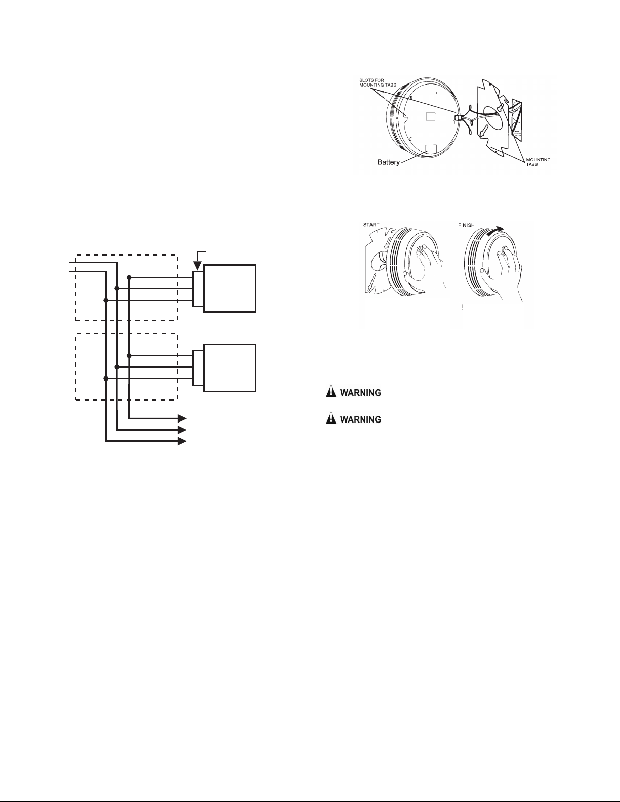
Heat alarms will not work without power. A battery must be connected
to the alarm to maintain proper alarm operation if AC power supply is cut off by
an electrical fire, an open fuse or circuit breaker, or for any other reason. In
the event of AC power failure, the battery will supply power for a minimum of
24 hours.
Heat alarms may not sense a fire that starts where heat cannot reach
the alarms such as in chimneys, in walls, on roofs, or on the other side of
closed doors. Smoke alarms should also be placed in each bedroom as well
as in the common hallway between them.
Heat alarms also may not sense a fire on another level of a residence
or building. For example, a second-floor alarm may not sense a first-floor or
basement fire. Therefore, alarms should be placed on every level of a
residence or building.
The horn in your heat alarm meets or exceeds current audibility
requirements of ANSI/UL 539. owever, if the heat alarm is located outside
a bedroom, it may not wake up a sound sleeper, especially if the bedroom
door is closed or only partly open. If the alarm is located on a different level of
the residence than the bedroom, it is even less likely to awaken people
sleeping in the bedroom. In such cases, the National Fire Protection
550-0158
Pg. D-2

Figures 2, 3, 4 & 5 are reprinted with permission from NFPA 72, National Fire Alarm Code®,
Copyright ©2010, National Fire Protection Association, Quincy, A 02169. This reprinted
material is not the complete and official position of the National Fire Protection Association on the
referenced subject which is represented only by the standard in its entirety.
National Fire Alarm Code® and NFPA 72® are registered trademarks of the
National Fire Protection Association, Inc., Quincy, A 02169.
550-0158
Pg. D-3
FIGURE 4: IN DWELLING UNITS WIT MORE T AN ONE SLEEPING
AREA, A SMOKE ALARM MUST BE PROVIDED TO PROTECT EAC
SLEEPING AREA IN ADDITION TO SMOKE ALARMS REQUIRED IN
BEDROOMS.
In addition to smoke alarms outside of the sleeping areas and in each
bedroom, NFPA 72 requires the installation of a smoke alarm on each
additional level of the dwelling unit, including the basement. These
installations are shown in FIGURE 5. The living area smoke alarm should be
installed in the living room or near the stairway to the upper lever, or in both
locations. The basement smoke alarm should be installed in close proximity to
the stairway leading to the floor above. Where installed on an open-joisted
ceiling, the smoke alarm should be placed on the bottom of the joists. The
smoke alarm should be positioned relative to the stairway so as to intercept
smoke coming from a fire in the basement before the smoke enters the
stairway.
Figure 3
Figure 3: A SMOKE ALARM MUST BE LOCATED BETWEEN T E
SLEEPING AREA AND T E REST OF T E DWELLING UNIT AS WELL AS IN
EAC BEDROOM.
In dwelling units with more than one bedroom area or with bedrooms on
more than one floor, more than one smoke alarm is required, as shown in
FIGURE 4.
FIGURE 2: A SMOKE ALARM MUST BE LOCATED ON EVERY LEVEL OF
DWELLING UNIT, INCLUDING BASEMENT, WIT IN EAC SLEEPING
ROOM AND OUTSIDE SLEEPING AREAS.
Where to Locate the Required S oke Alar s. The major threat from fire in
a dwelling unit occurs at night when everyone is asleep. Persons in sleeping
areas can be threatened by fires in the remainder of the unit; therefore, smoke
alarms are best located in each bedroom and between the bedroom areas and
the rest of the unit as shown in FIGURE 3.
FIGURE 2
FIGURE 3
FIGURE 4
heat alarms, as shown in FIGURE 1, and the distance to the wall is reduced to
12 ½ ft. (3.8 m). Since ½ x 50 ft. (15 m) is 25 ft. (7.6 m), the distance between
alarms across open wood joists should not exceed 25 ft. (7.6 m), as shown in
FIGURE 1, and the distance to the wall is reduced [ ½ x 25 ft. (7.6 m)] to 12.5
ft. (3.8 m). The alarms are required to be mounted on the bottom of the joists
and not up in joist channels.
Walls, partitions, doorways, ceiling beams and open joists interrupt the
normal flow of heat, thus creating new areas to be protected.
FIGURE 1
PLACEMENT OF HEAT ALARMS
T IS EQUIPMENT S OULD BE INSTALLED IN ACCORDANCE WIT
T E NATIONAL FIRE PROTECTION ASSOCIATION'S STANDARD 72
(National Fire Protection Association, Batterymarch Park, Quincy, MA 02269).
For your information, the National Fire Protection Association's Standard
72, reads as follows:
NFPA 72, 2010 Edition, Chapter 29, Section 29.5.1.1 Where required by
applicable laws, codes or standards for a specific type of occupancy, approved
single and multiple-station smoke alarms shall be installed as follows:
29.5.1.1 Where required by applicable laws, codes or standards for a specific
type of occupancy, approved single and multiple-station smoke alarms shall be
installed as follows:
1) In all sleeping rooms and guest rooms
2) Outside of each separate dwelling unit sleeping area, within 6.4m (21ft) of
any door to a sleeping room, the distance measured along a path of travel
3) On every level of a dwelling unit, including basements
4) On every level of a residential board and care occupancy (small
facility),including basements and excluding crawl spaces and unfinished
attics
5) In the living area(s) of a guest suite
6) In the living area(s) of a residential board and care occupancy (small facility)
29.5.1.2 Where the area addressed in 29.5.1.1(2) is separated from the
adjacent living areas by a door, a smoke alarm shall be installed in the area
between the door and the sleeping room, and additional alarms shall be
installed on the living area side of the door as specified by 29.5.1.1 and
29.5.1.3.
29.5.1.3 In addition to the requirements of 29.5.1.1(1) through 29.5.1.1(3),
where the interior floor area for a given level of a dwelling unit, excluding
garage areas, is greater than 93m2(1000ft2), smoke alarms shall be installed
per 29.5.1.3.1 and 29.5.1.3.2.
29.5.1.3.1 All points on the ceiling shall have a smoke alarm within a distance
of 9.1m (30ft) travel distance or shall have an equivalent of one smoke alarm
per 46.5m2(500ft2) is evaluated by dividing the total interior square footage of
floor area per level by 46.5m2(500ft2).
29.5.1.3.2 Where dwelling units include great rooms or vaulted/cathedral ceil-
ings extending over multiple floors, smoke alarms located on the upper floor
that are intended to protect the aforementioned area shall be permitted to be
considered as part of the lower floor(s) protection scheme used to meet the
requirements of 29.5.1.3.1.
The installation of additional alarms of either the smoke, heat or CO type
should result in a higher degree of protection. Adding alarms to rooms that are
normally closed off from the required alarms increases the escape time
because the fire does not need to build to the higher level necessary to force
smoke out of the closed room to the required alarms. As a consequence, it is
recommended that the householder consider the installation of additional fire
protection devices.
owever, it should be understood that NFPA 72 does not require additional
smoke alarms over and above those called for in FIGURES 2, 3, 4 and 5
where required smoke alarms are shown.

Near fluorescent light fixtures. Electrical "noise" from nearby fluorescent
light fixtures may cause a nuisance alarm. Install alarms and fluorescent
light on separate electrical circuits
Never disconnect an AC alarm to silence a nuisance
alarm. Use a cold damp rag or sponge and apply to the heat sensor
(silver disk) on the face of the unit. The alarm will automatically turn off
when the temperature of the sensor falls below 135oF. Do not
unnecessarily stand close to the alarm. The sound produced by the
alarm is loud because it is designed to awaken you in an emergency.
Prolonged exposure to the horn at a close distance may be harmful to
your hearing.
INSTALLATION OF HD135
New Construction: alarm head should not be installed until AFTER painting
and construction are finished and cleaned up.
MOUNTING OUTLET BOX
Use a 2" x 3" switch box or a 4" square or octagon junction box. Mount a box
for each alarm. If wall mounting is desired, be sure the box screws are
oriented to upper right and lower left corners. Be sure to use supplied
Mounting Plate.
WIRING/GENERAL
1. Use ANSI/UL Listed cable with Class1 insulation.
2. Observe local code requirements. Use the box clamps to anchor cable to
outlet box.
3. Metal outlet boxes must be grounded to earth ground.
4. NOTICE: USE ONLY DURACELL®MN 1604 BATTERY WIT T E D135
EAT ALARM.
CAUTION: Turn off electricity to prevent S OCK and damage to alarm. Be
sure the power line to the alarm is not controlled by any on/off switch, or other
type of switch, other than a fuse or circuit breaker.
IMPORTANT: Insure that all fluorescent lighting fixtures are properly grounded.
NOTICE: T E WIRING TO BE USED S ALL BE IN ACCORDANCE WIT
T E PROVISIONS OF ARTICLE 300.3 (B) 210 OF T E NATIONAL
ELECTRICAL CODE, NFPA 70. WIRE INSTALLATION S OULD BE
PERFORMED ONLY BY A LICENSED ELECTRICIAN.
WIRING ONE HEAT ALARM
1. Run a minimum of 16 gauge, 2-conductor cable, plus ground (3 wires) to
the alarm junction box from a power supply. Use ANSI/UL Listed Class
1 wire.
NOTICE: T E WIRING TO BE USED S ALL BE IN ACCORDANCE WIT
T E PROVISIONS OF ARTICLE 300.3(B) 210 OF T E NATIONAL
ELECTRICAL CODE, NFPA 70.
2. Make wire connections to the supplied plug-in connector as follows: black to
black, white to white, and connect the ground wire to the metal outlet box.
PLUG
HEAT
ALARM
BLK-120VAC
L1-220VAC 1
WHT-120VAC
L2-220VAC 11
RED / YEL 10
HOT
NEUT POWER
TANDEM
550-0158
Pg. D-4
FIGURE 6
FIGURE 5: A SMOKE ALARM MUST BE LOCATED ON EAC LEVEL IN
ADDITION TO EAC BEDROOM.
IMPORTANT CONSIDERATION
NFPA 72, 2010 Edition, Chapter 29, Section 29.8.1.4(5)(b) states:
“Smoke alarms installed in one- and two-family dwellings shall not
remain in service longer than 10 years from the date of manufacture.”
Smoke alarms should be replaced for the following reasons:
Dust, dirt, and other environmental contaminants can affect your smoke
and heat alarm over a prolonged period.
Fast changing industry consensus standards and codes on all smoke and
heat alarms make it advisable to periodically upgrade your devices to
maximize life safety.
Assurance that your smoke and heat alarm needs are kept abreast with the
constantly improving electronic technology.
Smoke and heat alarms are recognized as one of the lowest cost ways to
protect dwelling inhabitants against the danger of fire(s). It makes good
common sense to periodically replace and update your smoke alarm that
contributes so much to life safety.
MOUNTING LOCATION
This heat alarm can be mounted on a ceiling or wall with equal efficiency in
either location.
Ceiling location-heat alarm should be mounted at least 4 inches (100
mm) from a wall.
Wall location-locate the top of the heat alarm not less than 4 inches (100
mm) or more than 12 inches (300mm) from the ceiling.
FIGURE 5
FIGURE 6: RECOMMENDED EAT ALARM MOUNTING LOCATIONS
The placement of the alarm is critical if maximum speed of fire detection is
desired. Thus, a logical location for a alarm is the center of the ceiling. At this
location, the alarm is closest to all areas of the room.
LOCATIONS TO AVOID
Placing heat alarms where they will not operate properly causes nuisance
alarms. To avoid nuisance alarms, do not place heat alarms:
Where temperatures are regularly below 40oF (4.44oC) or above 100oF
(37.78oC).
In air streams passing by kitchens. It is possible normal air currents
can draw cooking heat into the sensor of a unit near the kitchen. If you
experience frequent unwanted alarms from a unit near your kitchen, try
relocating it. Do not install your heat alarm over a stove or a range.
In dead air spaces at the top of a peaked roof or in the corners
between ceilings and walls. Dead air may prevent heat from reaching a
alarm. See FIGURES 1 and 6 for recommended mounting locations.
NOTICE: RED-YELLOW WIRE: T E RED-YELLOW WIRE FROM T E EAT
ALARM IS FOR TANDEM CONNECTION ONLY. DO NOT USE, AND DO
NOT REMOVE INSULATION CAP UNLESS CONNECTING ANOT ER EAT
ALARM.

TESTING
Use a hair dryer and direct hot air towards the silver disk on the face of the
alarm or use a portable soldering iron and place it against the heat sensor.
Never use an open flame of any kind to test your
heat alarm. You may ignite and damage the alarm as well as your home.
Heat alarms are not to be used with alarm guards unless
the combination has been evaluated and found suitable for that purpose.
TO RETURN A HEAT ALARM
Should you experience problems with your heat alarm, proceed as follows:
1. Turn off electrical power to the heat alarm.
2. Twist the heat alarm counter-clockwise to remove it from its mounting plate.
3. Unplug the connector from the back of the heat alarm. Do not remove the
wire connection; leave the connector for your replacement heat alarm.
4. Remove battery from heat alarm. Do not ship heat alarm with battery still
attached to battery clip.
5. Carefully pack (the manufacturer cannot be responsible for consequential
damage) and return to the manufacturer. Include complete details as to
exact nature of difficulties being experienced and date of installation.
6. Return to: Gentex Corporation, 10985 Chicago Drive, Zeeland, Michigan,
49464. Prior to returning, call Gentex at 1-800-436-8391 or e-mail
Service Department.
3. Place the heat alarm up to the mounting plate, rotating it clockwise until
alarm firmly snap locks into place. Keep the heat alarm parallel to the
mounting plate so upper and lower tabs on the plate seat correctly into the
heat alarm.
1. Run a minimum of 16 gauge, 3-conductor cable, plus ground (4 wires) to
the first alarm junction box from a power supply and between all alarms that
are to be tandem connected together. Use ANSI/UL Listed Class 1 wire.
2. Make wire connections to the supplied plug-in connector as follows: black to
black, white to white, 3rd conductor to the red/yellow wire. The red/yellow
wire should be stripped to make the connection. Connect ground wire
between metal outlet boxes.
NOTICE: TANDEM INTERCONNECTING MODELS
DO NOT connect Gentex smoke or heat alarms to other manufacturers'
smoke alarms.
All units connected in tandem MUST get their power from the same circuit,
that is, all heat and/or smoke alarms in tandem must be controlled by the
same fuse or circuit breaker.
After installation to verify proper working conditions all horns must sound in
this system.
CAUTION: Failure to observe any of the conditions set forth may cause
system malfunction and damage to the alarm.
BATTERY INSTALLATION
1. Remove heat alarm from mounting plate by turning counter-clockwise.
2. Remove AC power connector and unsnap power leads from the top of
the old battery. Snap new battery onto snaps and reinsert battery through
hole in the back of the alarm. WARNING: Units with battery back-up will
not provide power or transmit an alarm to AC only units in the event of an
AC power failure. All battery back-up units in tandem with good batteries
will operate normally during an AC power failure.
3. Use only Duracell®MN 1604 battery with the D135 Series heat alarm.
CAUTION: Units with battery back-up will not provide power or transmit an alarm
to AC only units in the event of an AC power failure. All battery back-up units in
tandem, with good batteries, will operate normally during an AC power failure.
ROTATE ALARM
TO UPRIG T
POSITION
WORK CONNECTOR
WIRES BACK T ROUG
OLE IN ADAPTER PLATE
WIRING TWO OR MORE HEAT ALARMS
Tandem Installation
NOTICE: ALL EAT ALARMS IN A TANDEM INSTALLATION MUST BE
CONTROLLED BY T E SAME FUSE OR CIRCUIT BREAKER. OT ERWISE
TANDEM UNITS WILL NOT OPERATE. TANDEM UNITS WILL OPERATE IN
T E EVENT OF AC POWER FAILURE IF BATTERY IS CONNECTED TO
T E EAT ALARM.
LIMITATIONS: A maximum of (12) smoke alarms (9120/9123, 7100/ 7103,
9220/9223 or 7200/7203) may be tandem connected together. A total of (12)
smoke alarms and (6) heat alarms may be tandem interconnected together.
Do not exceed 125 feet between each alarm. Do not exceed 1125 feet
between first and last alarm.
A maximum of six (6) smoke alarms with relay options (9120F/9123F,
9220F/9223F, 7100F/7103F, 7200F/7203F, 710CS/713CS or 7109CS/7139CS)
may be tandem interconnected. If a D135 is interconnected, a maximum of
(5) 9120F/9123F, 9220F/9223F, 7100F/7103F, 7200F/7203F, 710CS/713CS or
7109CS/7139CS and (3) D135 units may be tandem interconnected.
Wire used for interconnecting shall be in accordance with the latest edition of
Article 760 of the National Electrical Code (NEC) and NFPA 70, and must not
exceed a resistance of 10 ohms.
AC
POWER
ELECTRICAL
BOX
HEAT
ALARM
HEAT
ALARM
QUICK DISCONNECT
TYPE PLUG
ELECTRICAL
BOX
HOT / BLACK
(220VAC L1)
NEUTRAL / WHITE
(220VAC L2)
TANDEM WIRE
RED / YELLOW
550-0158
Pg. D-5
MOUNTING: PLATE & HEAT ALARM
1. Lace the connector through the provided mounting plate and secure the
plate to the junction box.
2. Plug the wire connector into the heat alarm base.

For a period of 12 months from the date of purchase, or a maximum of 18 months from the
date of manufacture, Gentex warrants to you, the original consumer purchaser, that your heat
alarm will be free from defects in workmanship, materials, and construction under normal use and
service. If a defect in workmanship, materials, or construction should cause your heat alarm to
become inoperable within the warranty period, Gentex will repair your heat alarm or furnish you
with a new or rebuilt replacement heat alarm without charge to you except for postage required to
return the heat alarm to us. Your repaired or replacement heat alarm will be returned to you free of
charge and it will be covered under this warranty for the balance of the warranty period.
This warranty is void if our inspection of your heat alarm shows that the damage or failure was
caused by abuse, misuse, abnormal usage, faulty installation, improper maintenance, or repairs
other than those performed by us.
ANY WARRANTIES I PLIED UNDER ANY STATE LAW, INCLUDING I PLIED WARRANTIES
OF ERCHANTABILITY OR FITNESS FOR A PARTICULAR PURPOSE, APPLY ONLY FOR THE
WARRANTY PERIOD SPECIFIED ABOVE. PLEASE NOTE THAT SO E STATES DO NOT
ALLOW LI ITATIONS ON HOW LONG AN I PLIED WARRANTY LASTS, SO THE ABOVE
EXCLUSION AY NOT APPLY TO YOU.
GENTEX WILL NOT BE LIABLE FOR ANY LOSS, DA AGE, INCIDENTAL OR
CONSEQUENTIAL DA AGES OF ANY KIND ARISING IN CONNECTION WITH THE SALE, USE,
OR REPAIR OF THIS HEAT ALAR . PLEASE NOTE THAT SO E STATES DO NOT ALLOW
THE EXCLUSION OR LI ITATION OF INCIDENTAL OR CONSEQUENTIAL DA AGES. SO THE
ABOVE EXCLUSION AY NOT APPLY TO YOU.
If a defect in workmanship, materials, or construction should cause your heat alarm to become
inoperable within the warranty period, you must return the heat alarm to Gentex postage prepaid.
You must also pack the heat alarm to minimize the risk of it being damaged in transit. You must
also enclose a return address. heat alarms returned for warranty service should be sent to: Gentex
Corporation, 10985 Chicago Drive, Zeeland, I 49464.
If we receive a heat alarm in a damaged condition as the result of shipping, we will notify you
and you must file a claim with the Shipper.
THIS LI ITED WARRANTY GIVES YOU SPECIFIC LEGAL RIGHTS. YOU AY ALSO HAVE
OTHER RIGHTS WHICH VARY FRO STATE TO STATE.
LI ITED WARRANTY
6-1-98
550-158-HAB
Important Notice:
These materials have been prepared by Gentex Corporation ("Gentex") for informational purposes only, are necessarily summary, and are not purported to serve as legal advice and should not be used as
such. Gentex makes no representations and warranties, express or implied, that these materials are complete and accurate, up-to-date, or in compliance with all relevant local, state and federal laws,
regulations and rules. The materials do not address all legal considerations as there is inevitable uncertainty regarding interpretation of laws, regulations and rules and the application of such laws,
regulations and rules to particular fact patterns. Each person's activities can differently affect the obligations that exist under applicable laws, regulations or rules. Therefore, these materials should be used
only for informational purposes and should not be used as a substitute for seeking professional legal advice. Gentex will not be responsible for any action or failure to act in reliance upon the information
contained in this material.
GENTEX CORPORATION
10985 CHICAGO DRIVE, ZEELAND, I 49464
PHONE: 1-800-436-8391
www.gentex.com Pg. D-6
This manual suits for next models
3
Table of contents
Other Gentex Security System manuals