OVERVIEW • PRODUCT DESCRIPTION
TECHNICAL SUPPORT: 1.800.283.5936 (USA) OR 1.801.975.3760
7
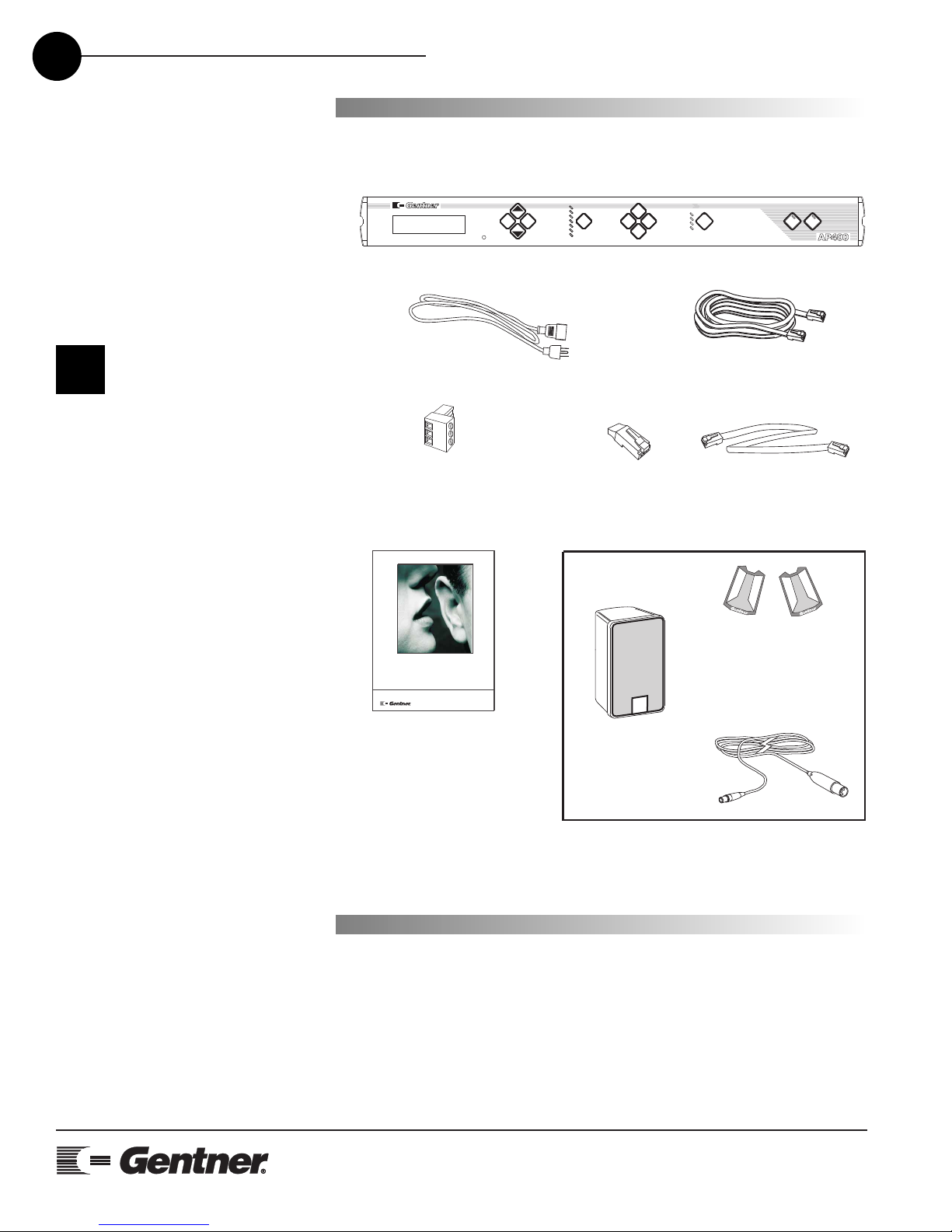
Product Description
The AP400 performs a variety of complex, integrated audio functions,
all implemented using digital signal processors (DSPs). In the simplest
terms, the AP400 is a microphone mixing matrix. As such, all micro-
phone-mixing parameters can be customized and any input or combi-
nation of inputs can be routed to any output. Adjustments in routing,
level and all other functions can be made in one of three ways: front-
panel programming, presets activated through a closure on the rear
panel, and RS232 serial interface.
However, the AP400 is much more than a simple microphone-mixing
matrix. The AP400 operates on four basic principles: gating micro-
phones, Distributed Echo Cancellation™, decisions for each micro-
phone, and network architecture. The AP400 gates microphones on
and off when the sound within a microphone’s acceptance pattern
reaches a certain level. The AP400 provides Distributed Echo
Cancellation which makes decisions for each microphone individually,
based on each microphone’s specific conditions.
Each microphone reacts independently, observing its own ambient lev-
els and making decisions based on its individual environment. Thus, a
microphone located in a highly reverberant part of a conference room
is able to compensate for the changes in its own area. The AP400 moni-
tors audio levels at each microphone and reduces the mixing level for
microphones not in use and/or eliminates echo. This improves the
audio quality for the listener and decreases the possibility of feedback.
An integrated telephone interface provides the AP400’s audioconfer-
encing capability and can be customized according to your needs.
The telephone interface can be set to automatically answer upon detec-
tion of a valid ring and automatically disconnect on loop drop or call
progress tones.
Finally, as part of its self-contained audio conferencing design, the
AP400 includes a built-in power amp. The amp delivers 5W of output
power into a 4 ohm speaker, eliminating the need to provide external
amps for the speakers.
While a single AP400 satisfies the requirements of most small audio-
conferencing environments, the system can also be expanded to sup-
ply additional connections or cover larger areas. The Audio Perfect™ G-
link network allows you to change the system configuration as you need
and control it from a central location.