Geokon BGK-408 User manual

BGK-408
VW Readout Box
Instruction Manual
(Rev E)
Copyright ©2009 China Genkon Instruments Co. Ltd.
The installation, maintenance and operation tasks on this instrument should be performed by professional technician.
China Geokon Instruments Co., Ltd. reserves the modification rights for its products. The product information is subject to
change without notice.
The information contained in this document belongs to China Geokon Instruments Co., Ltd. All of the information, data,
designs and drawings in this document are owned by China Geokon Instruments Co., Ltd. No part of this guide may be
reproduced or copied, disclosed to outside directly or indirectly, by any means (including photocopying or any other means),
without the written consent of China Geokon Instruments Co., Ltd.

Manual of BGK-408 2
CONTONT
1.Main Function..............................................................................................................................3
1.1 BGK-408 Front Panel .........................................................................................................3
1.2 Port Introduction.................................................................................................................5
1.2.1 Transducer Port........................................................................................................5
1.2.2 Communication Port ................................................................................................5
1.2.3 Outer Power Port......................................................................................................5
2 Beginning.......................................................................................................................................6
2.1 Getting started.....................................................................................................................6
2.2 Type of Transducers and its Setting ....................................................................................7
2.3 Shortcut Measuring.............................................................................................................8
2.3.1 Routine Manual ―MEAS‖ Mode..............................................................................8
2.3.2AUTO.....................................................................................................................10
2.3.2.1Automatic Measuring of Single Terminal Box....................................................10
2.3.2.2 Multiple Terminal Boxes.....................................................................................12
3 Main Menu...................................................................................................................................14
3.1 Interface of Main Menu ....................................................................................................14
3.2 Menu Selection .................................................................................................................15
3.2.1 ―Storage Address‖ ..................................................................................................15
3.2.2 ―Storage Page‖ .......................................................................................................16
3.2.3 ―Data Clean-up‖.....................................................................................................16
3.2.4 ―Data Renewing‖ ...................................................................................................16
3.2.5 ―Timing Turnoff‖ ...................................................................................................17
3.2.6 ―Data View‖ ...........................................................................................................18
3.2.7 ―Date/Time Setting‖...............................................................................................19
3.2.8 ―Display Model‖ ....................................................................................................21
3.2.9 ―Exit‖ .....................................................................................................................22
4 Maintenance.................................................................................................................................22
4.1 Daily Maintenance............................................................................................................22
4.2 Calibration.........................................................................................................................23
4.3 Trouble Shooting...............................................................................................................23
4.4 Limits of Liability and Guarantee.....................................................................................24
5 BGK-408 Specification................................................................................................................26
AppendixA BGK-408 Use Method of Communication and Setting Software............................27
A.1 Read the Data Stored in Readout Box......................................................................................27
A.2 the channel configuration method of BGK-408 and BGK-AC networking.............................29
A.3 BGK-408 and BGK-AC measuring method in networking.....................................................34
Manual of BGK-408 3
1.Main Function
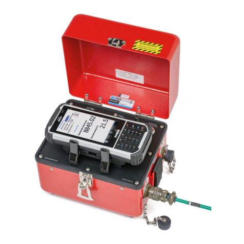
BGK-408VW Readout Box is manufactured by China Genkon Instruments for matching
the VW transducers. The main characters are:
1) The complete sealed and portable construction, the pellicle and water-proof panel and a
big and apheliotropic screen LCD can make the readout box work under any weather
condition;
2) By alternative operation with hand or machine, the user can set the original parameters
and work condition at will according to the suggestion show in the menu;
3) Such shortcut keys as 【 】、【MEAS】、【POS】、【AUTO】can improve the working
efficiency;
4) The inner data storage with big capability can store the measurements while displaying
the data, and can store 1920 pieces of instruments at most;
5) By the computer and the relative communicate software, the RS-232C communication
port can realize the readout box controlling,real time measuring, parameter updating,
data communicating and some other functions;
6) By RS-485 communication port,the readout box can be connected to BGK-AC
Terminal Box without any sew;
7) The referential information about the outer power, inner battery and the voltage are
shown completely and exactly;
8) High accuracy and stability;
9) Turn off automatically if no operation in a long time;
10) The big capability Li-battery can ensure the long and steady work。
1.1 BGK-408 Front Panel
BGK-408 VW Readout Box uses pellicle keys, there are 【ON】、【 OFF】、 【】、
【MEAS】、【POS】、【AUTO】、【MENU】、【▲】、【▼】、【SET】, among which【 】、【MEAS】、
【POS】、【AUTO】are shortcut keys,and【MENU】can realize the parameters setting, and【▲】、
【▼】、【SET】are used as key combination. BGK-408 Front Panel is composed of the following
parts; please refer to P-1:

Manual of BGK-408 4
a) 128×64 lattice LCD, which can show four rows of characters;
b) ―TRANSDUCER‖ is for connection of the transducers;
c) ―CHARGER‖ is the charger jack for the inner battery or outer power supply;
d) ―RS-232/485‖ is for connection of the communication wire and terminal box or PC;
e) 【ON】【 OFF】is for turning on and off the power;
f) 【SET】is for setting the parameter;
g) 【AUTO】is for the automatic measuring and storing data after connecting BGK-AC;
h) 【POS】is for the range setting of frequency sweep of different sensors;
i) 【MEAS】is used in normal condition and when data storing is needed;
j) 【 】press once to turn on the apheliotropic and another to turn off。
k) 【▲ ▼】is for address storage and the combination use when setting the mode or the
menu;
l) 【 】(Enter) is for data storage confirmation under measuring status and is for optional
item switch or confirmation under the setting status.
P-1 BGK-408 Operation Panel
Once turning on, press any key the inner buzzer will sound, and meanwhile the information
will show on LCD to respond the operation.
Note: Though the operation panel of BGK-408 uses pellicle key, do not use nail or other

Manual of BGK-408 5
hard things to press to avoid the keys distortion or uselessness.
1.2 Port Introduction
1.2.1 Transducer Port
BGK-408VW Readout Box is equipped with special cable, one end is a ten-core aero-jack
connected to ―TRANSDUCER‖ and the other end is clips with five colors of leads,among
which the ―red‖ and ―black‖ leads are connected to the VW signal output end, and ―green‖ and
―white‖ leads are connected to the temperature signal output end of instruments; And all the
leads above are not in polarity division, thus the connection position can be changed. That
is ,‖red‖and ―black‖can be changed and ―green‖and ―white‖can be changed. The yellow lead
clip is used to connect with the shielding line of instruments.
When use China Genkon Instruments, all the clips are connected to the wire with the same color.
1.2.2 Communication Port
BGK-408VW Readout Box has RS-232C and RS485 port, and there is an obvious sign
―RS-232/485‖ in the corresponding position on the panel.
By the special cable, can realize:
a.) RS-232C connected to PC or nine-core of RS232;
b.) RS-485 connected to BGK-AC Terminal Box。
1.2.3 Outer Power Port
BGK-408VW Readout Box has a port for outer power, and there is an obvious sign
―CHARGER‖ in the corresponding position on the panel.
When outer power supplies, there will be a signal of ― ‖ shown on LCD, and the inner spare
battery supplies, there will be a signal of ― ‖ shown on LCD, while the voltage is not enough,
there will be ― ‖ . When the outer power is connected, it will also charge the inner spare battery
until to the upper limit of the voltage and turn off automatically to protect the battery from
over-charge.
There will be no difference for the measuring results no matter use the outer power or the
battery to supply BGK-408.

Manual of BGK-408 6
2 Beginning
2.1 Getting started
Press ―ON‖ and BGK-408VW Readout Box will start, there will show the following interface
on LCD, and if it has been connected to the instruments before started, it will be in measuring
function directly.
Geokon
VW Readout box
2004-03-21
15:34:52
P-2 Interface after getting started
Once BGK-408 is getting started, the inner system will do self-checking automatically,
and the items include storage、battery voltage and real time clock. The sign“ ” on the upper
right corner shows in the model of battery supply (“”means battery under
voltage), The sign“ ” shows the readout box in charging status and outer
power is connected.
When the battery is not enough and no outer power, there will show the following interface
as P-3, and the readout box will turn off automatically in 15m, now it should be recharged in time.
P-3 Interface of lacking battery voltage
The readout box will turn off automatically in the following conditions:
a) Under power supply condition, if there is no key operation over 15m, it will turn off
automatically;
b) Under battery supply condition, if the battery voltage is not enough, even if there is
Please charge the battery
Turn off in 15minutes

Manual of BGK-408 7
key operation, it will turn of automatically in 15m.
In normal condition, the self-checking will be finished in 1s, and after this BGK-408 will
self-identify automatically if there is any transducer connected. If there is no transducer or connect
transducers after self-checking, the panel will keep on the interface after getting started until
switch to other interface or turn off by hand. And if the readout box connects transducers before
getting started, it will switch in ―measuring‖ model directly after self-checking and show the
current modulus and temperature.
00-01-01 B
Modu.:
2583.8 F
Temp.:
23.6℃
P-4 Interface of measuring mode after self-testing
If transducer has been connected, after self-checking the measuring mode will be the same as
the last time, which is suit for most of Geokon transducers. If there is other type of transducers,
the mode needs to be resettled after getting started. And if there is no instrument, it is need to press
―MEAS‖ to enter in measuring status. .
2.2 Type of Transducers and its Setting
In order to fit different types of transducers, there are six kinds of POS models in BGK-408,
which can be set anytime in normal measuring condition.
After getting started, no matter in which condition, the corresponding POS models should be
chosen for certain instruments. See Table 1 to determine the best mode for China Genkon
Instruments.
Table 1 - POS MODEL options (A-F)
POS model
Use with Geokon
Model No.
Calculation
Units
Frequency
Sweep (Hz)
A
all
f210-3
F or
450-5000
B-POS MODE
F-Module,
HZ-Frequency
Head site of storage
P. No.―Box.No.―Point. No.
℃- T e m p e r a t u r e
Ω-Resistance

Manual of BGK-408 8
B
4300BX,4400,
4500,4600,4700,
4800,4900/11
Digits
1200-3500
C
4000/4200
400-1200
D
4100
1800-3500
E
4300EX
2500-6000
F
others
2500-4000
Operation method: Press ―MEAS‖to enter in measuring status, there appears the following
interface:
P-5 Interface of regular measuring mode
Press ―POS‖(Incentive mode) to choose the right frequency sweep mode, the model includes
A-B-C-D-E-F and the displayed readings are for the instruments.
If it is need to store the current frequency sweep mode, just press ―SET‖, and then press
―MEAS‖ to the measuring mode. Thus even turn off the readout box, it will still measure in this
mode after turning on again.
Note: If the chosen POS MODEL is not equipped with the instruments, the readings might be
not stable or no readings, even wrong.
2.3 Shortcut Measuring
2.3.1 Routine Manual ―MEAS‖ Mode
Press “MEAS” in any condition can entry measuring mode.
Routine measuring means in normal condition, operate BGK-408 manually and store data
in turn. Take BGK-4000 for example, the operation steps are:
1) Press ―MEAS‖ after getting started, and refer P-6:
00-01-01 B
Modu.:
2583.8 F
Temp.:
23.6℃

Manual of BGK-408 9
Module:00-01-01 B
________ F
Temperature:
________℃
P-6 Interface of regular measuring mode
2) Press ―POS‖ to choose proper POS MODEL according to the instruments, for instance,
chooses ―C‖. Press down this button, the POS models can be changed in A-F.
3) Connect transducer and the readout box, please refer to P-7:
Module:00-01-01 C
924.2 F
Temperature:
24.3℃
P-7 Interface of regular measuring
4) Store current readings (if need to store manually, please press ― ‖) in 00-01-01,
and at this moment, there will show the following information as
P-8-Indicating interface of data storage
5) If the readout box doesn’t connect to another instruments, there will show information
as P-9, and pay attention to the storage number has been 00-01-02;
Module:00-01-02 C
________ F
Temperature:
________℃
P-9-Interface after automatic logging
6) Press “▲” 或“▼” to change the storage address; and if it only needs to change the
channel number, just press “▲” 或“▼” once.And if it needs to change the channel
number rapidly, just press“▲”或“▼”continuously, and the channel and box number
will increase and reduce rapidly in order, stop pressing until meet the requirements. If it
needs to change the storage interface, please refer to the Section of Main Menu.
Data has been stored,
Please connect next instruments!

Manual of BGK-408 10
7) Connect other transducers and repeat Step 4.
2.3.2 AUTO
Press “AUTO” in any condition can entry “AUTO” Mode (only limit to the case
connecting terminal box).
―AUTO‖ Mode is mainly used for the communication between BGK-408 and BGK-AC to
realize the automatic data logging and storing.
In ―AUTO‖ Mode, connect the Readout Box, transducer, and Terminal Box correctly (the
special communication lead of the Readout Box and Terminal Box is selected to buy), and then
turn on the Readout Box and Terminal Box and press ―AUTO‖ to start automatic measuring.
During measuring, the readout box can recognize automatically if there is an instrument
connected to the terminal box. Please pay attention that in one channel, there are two transducers,
the main one is vibrating wire and the other is thermometer, the testing process is as follows:
1) If both transducers are connected, they will be measured and data will be stored;
2) If the leads of both transducers are open, the system will skip to next channel directly
without measuring;
3) If the lead of only one transducer is open, the system will skip this and measure
another one;
4) If both the transducers are disabled but the lead doesn’t open, they will still be
measured but the result is no reads or disabled reads;
5) If there are no transducers, BGK-408 won’t measure and skip to next channel rapidly.
2.3.2.1 Automatic Measuring of Single Terminal Box
The automatic measuring method of single Terminal Box is:
1) Combine with P-1, connect the readout box with the terminal box with a special
communication lead as shown in P-10;
2) Connect signal cable of the transducer and the terminal box correspondingly;

Manual of BGK-408 11
Terminal Box 1#
RS485
AB
Signal Export of sensor
Black Red Green White Shielded
BGK-408 Readout Box
RS485
Signal Import of sensor
Signal cable of
Sensor
Signal cable of
Communication
Controlling
P10-Automatic measuring of Signal Box
3) If the terminal box has been turned off, please turn on.
4) Turn on the readout box, and then in ―SET‖ menu press ―▲‖ or―▼‖ to choose the
storage interface 00 or 01(default interface is 00),and then press― ‖ to affirm.
5) Press ―AUTO‖, the following interface will show and measure the transducers, display
readings and store automatically.
Automatic measuring
Please wait…
Module:00-01-01 B
××××. ×F
Temperature:
××.×℃
P-11-Interface of automatic measuring
6) Connect another terminal box, and repeat Step 4.
Note:
1) The serial number of the terminal box should be selected among 01 to 15 without
repeat;
2) The quantity of the terminal box in one page should not be more than 15, and if the
quantity is more than 15, another page should be selected, and now the serial number
can be repeat;
3) The communication and signal lead can be extended to 1200m for the remote
measuring;
4) VW transducers or those with the same type can be connected into one terminal box.

Manual of BGK-408 12
2.3.2.2 Multiple Terminal Boxes
Connect all the communication and signal leads of the terminal boxes (2 to 15 sets) in series
or in parallel to form a net. (Please refer to the Instruction Manual of BGK
-
AC32/64 for the
detailed connection method) Set the serial number of the terminal box from No. 01 to No. 15.
Two same serial numbers in one net are not allowed.
P-12 is the sketch map for the net of multiple terminal boxes.
Terminal Box 1#
RS485
AB
Signal Export of sensor
Black Red Green White Shielded
Terminal Box 1#
RS485
AB
Signal Export of sensor
Black Red Green White Shielded
Terminal Box 1#
RS485
AB
Signal Export of sensor
Black Red Green White Shielded
……
B R G W S
BGK-408 Readout Box
RS485
Signal Import of sensor
图12-Measuring Sketch Map of Multiple BGK-AC
In ―AUTO‖ Mode, it is necessary to set in advance the equipped type and mode with the
instruments by software.
There are two connection styles for the measuring of multiple terminal boxes, one is early
BGK-AC, in which there are two RS communication ports and two transducer signal exports,
and these four ports are connected in parallel inside the box. The character of all ports is the same.
During the connection, just connect the terminal box one by one, and then connect the readout
box to the first or the last terminal box. Please refer to P-13.

Manual of BGK-408 13
P-13-Net of Terminal Boxes
The newly terminal box has one communication and one signal port. Refer to the above
picture and connect the A and B port of adjacent terminal boxes in parallel, then connect
signal lead with the same color of each transducer also in parallel, and connect the
communication leads and signal leads of the terminal box and readout box respectively.
When connecting, the following items should be ensured:
1) The connection between communication and transducer signal lead is correct;
2) Power of all terminal boxes is on;
3) Turn on the readout box, and then in ―SET‖ menu press ―▲‖ or―▼‖ to choose the
storage interface as 00 or 01(default interface is 00), and then press― ‖ to store and
exit the current setting to enter in main menu.
4) Press ―AUTO‖, the following interface will show as in P-14 and measure the
transducers in the order of box number and channel number, display readings and store
automatically in corresponding areas.
Automatic measuring
Please wait
Module:00-01-01 B
××××. ×F
Temperature:
××.×℃
P-14-Interface of automatic measuring
Terminal
Box 1
Terminal
Box 2
Terminal
Box 15
……
Port for BGK-408 RS485
Port for BGK-408
Sensor clip
RS485Commun
ication Lead
RS485Commun
ication Lead
Signal Lead of sensor
Sketch Map of Ter. Boxes

Manual of BGK-408 14
5) The readout box will recognize the serial number and channel number of the terminal
box automatically and also the exact quantity of the instruments connected; and
measure one by one, skip the channel without transducers, show and store the readings.
The measuring time of each channel is less than 2s.
Note:
1)If the terminal boxes are more than 15, the data should be stored in two pages;
2)If there are more than two nets, two readout boxes should be adopted, or the data be
transferred to PC to measure again;
3)All terminal boxes should be set with in 1200m;
4)In remote measuring, the distance between the readout box and the furthest terminal box
is not more than 1200m;
5)Before connecting, each instruments should be checked by a readout box to make sure
the order of communication and signal leads and each transducer is in good condition;
6)During measuring, if there is no reading in some terminal box, the power should be
checked, and also the communication and signal leads.
3 Main Menu
In below introduction, the ―box number ―or ―channel number‖are not only referred in the
terminal box connection, sometime the ―channel number‖also can be the instruments number or
storage address in manual mode.
3.1 Interface of Main Menu
After getting started, press ―SET‖ to main menu, and the following interface will be shown.
Press ―▲‖ or―▼‖ to select, and the cursor(the black rectangle in P-15)will move relatively.
Then press ― ‖ to start and operate the items with the cursor.
P-15-Interface of main menu
Main menu(SET)
1. Address of storage
2. Page of storage
3. Clean up the data

Manual of BGK-408 15
3.2 Menu Selection
There are the following items in the menu of BGK-408: ①―Storage Address‖;②―Storage
Page‖;③―Data Clean-up‖;④―Data Renewing‖;⑤―Timing Turnoff‖;⑥―Data View‖;
⑦―Date/Time Setting‖;⑧―Mode Display‖;⑨ ―Exit‖.
3.2.1 ―Storage Address‖
It is used in normal manual measuring condition and need to store data which set the start
address. Please choose and execute ―head site of storage‖, Please refer to P-16.
P16-Interface of ―Head site of storage‖
At the beginning of this interface, the cursor is at the position of ―Box No.‖. When press
―‖ each time, the cursor will move between ―Box No.‖ and ―Channel No.‖.
At the position of the cursor, press ―▲‖ or ―▼‖ to change the data; And if it’s no need to
change, just press ― ‖ to move the cursor to the next one. The rule of changing data is:
a) ―Box No.‖is from ―01‖ to ―15‖;
b) ―Channel No.‖is from ―01‖ to ―64‖;
c) Press ―▲‖ quickly each time, the variable on the cursor will increase 1; and if the
cursor is under ―Box No.‖ or ―Channel No.‖, press ―▲‖ for more than 1s, the variable
will increase rapidly;
d) Press ―▼‖ quickly each time, the variable on the cursor will decrease 1; and if the
cursor is under ―Box No.‖ or ―Channel No.‖, press ―▼‖ for more than 1s, the variable
will decrease rapidly;
On this ―Head site of storage‖interface, press ―SET‖, store and exit out current setting, data
cursor is not changed and return to main menu status.
Note: After setting the box number and the channel number, only press‖ SET‖can store this
setting; Otherwise, it will not store.
Head site of storage
P. No.―Box.No.―Instru. No.
00―01―01

Manual of BGK-408 16
3.2.2 ―Storage Page‖
Choose and operate ―Storage Page‖, the following interface will show:
P-17-Interface of ―Page of storage‖
Press ―▲‖ or―▼‖ to select, and the cursor(the black rectangle in the above picture)will
move relatively; Then press ― ‖ to start and operate the items with the cursor, and the
information is stored in SRAM. Then the system returns to the main menu.
Note: As the system stores the selected items in real time, when it exists to the main menu,
the items or the cursor position may not the same as shown in P-15, but if only all the items
belong to the main menu, that will be regarded as normal.
3.2.3 ―Data Clean-up‖
Choose and operate ―Data Clean-up‖, the following interface will show:
P-18-Interface of ―Data Clean-up‖
In this interface, all stored data in SRAM will be marked with ―delete‖ sign,thus in ―Data
View‖ it will show ―No Storage‖, and in ―Data Upload‖ it will ―not upload‖. After finishing ―Data
Clean-up‖, the system will exit to main menu automatically.
Note: As the system stores the selected items in real time, when it exits to the main menu, the
items or the cursor position may not the same as shown in P-15, but if only all the items belong to
the main menu, that will be regarded as normal.
3.2.4 ―Data Renewing‖
Choose and operate ―Data Renewing‖, the following interface will show:
Page of storage
1.0 0
2.0 1
Cleanup the data
Please wait …

Manual of BGK-408 17
P-19-Interface of ―Data Renewing‖
In this interface, all stored data in SRAM that marked with ―delete‖ sign will renew,thus in
―Data View‖ it will show data completely, and in ―Data Upload‖ it will upload normally. After
finishing ―Data Renewing‖, the system will exit to main menu automatically.
Note: As the system stores the selected items in real time, when it exits to the main menu, the
items or the cursor position may not the same as shown in P-15, but if only all the items belong to
the main menu, that will be regarded as normal.
3.2.5 ―Timing Turnoff‖
Choose and operate ―Timing Turnoff‖, the following interface will show:
P-20-Interface of ―Timing Turnoff‖
Press ―▲‖ or―▼‖ to select in this interface, and the cursor(the black rectangle in the above
picture)will move relatively; Then press ― ‖ to start and operate ―Timing Turnoff‖ with the
cursor, and the information is stored in SRAM. Then the system returns to the main menu.
Note:
1) No matter there is any operation or not, ―Timing Turnoff‖ is imperative;
2) After setting, the system will turn off in 15m automatically;
3) As the system stores the selected items in real time, when it exits to the main menu, the
items or the cursor position may not the same as shown in P-15, but if only all the items
belong to the main menu, that will be regarded as normal.
Renew the data
Please wait …
Timing turnoff
1.Enable
2.Disable

Manual of BGK-408 18
3.2.6 ―Data View‖
All data stored in BGK-408 can be viewed.
First, it needs to choose the page that you want to view---choose and operate ―Page‖ in the
main menu, and then choose ―Data View‖, the following P-21 will show:
Module:00-01-01 B
2583.8 F
Temperature:
23.6℃
P-21-Interface of ―Data View‖
The shown information includes the current Page-Box No.-Channel No.、Model(A~F)、
Modulus F(or frequency, Unit: Hz)and Temperature℃ ( or resistance, Unit: Ω). If the
mode is ―Frequency and Resistance‖, the displayed information is: Frequency: ******.
**Hz, Resistance:*****Ω;If the mode is ―Modulus and Temperature‖, the displayed
information Is: Modulus:******.*F, Temperature:****℃(Note: If the used thermometer
is not from China Genkon Instruments, the displayed temperature may wrong. So now it is
suggested to set ―Frequency and Resistance‖)。Press ― ‖ in this condition, the measuring
time can be seen (refer to P-22). Press ― ‖ again and the interface will return to P-21.
If the selected note is empty or has been deleted, in ―Frequency and Resistance‖ Mode the
displayed is: Frequency: -------Hz, Resistance: ----Ω; or in ―modulus and temperature‖, the
displayed is: Modulus: -------F, temperature ----℃. Now press― ‖, ―No Data‖will show (Refer
to P-23)
00-01-01
Measuring time
2004-3-12 15:00
P-22-Interface of measuring time
In the interface of P-22, the first line is the Head Address 00-01-01. Press ―▲‖ or ―▼‖
to change the channel number,and the last line will be the time when the data stored:
―YY-MM-DD H: M‖. If the selected note is empty or has been deleted, ―No Data‖ will show (as
P-23).

Manual of BGK-408 19
P-23-Interface of ―No data‖
If the Box No needs to be changed, it should be changed before increasing to ―64‖ or
decreasing to ―01‖, and if it needs to change the Box No from 01 to 02,press―▲‖ continuously to
realize the changing of box number, that is from 00-01-64 to 00-02-01; Whereas, press
―▼‖.
Note:
a) ―Box No.‖ is from ―01‖ to ―15‖;
b)―Channel No.‖ is from ―01‖ to ―64‖;
c) Press ―▲‖ quickly each time, the data on the cursor will increase 1; and if the cursor is
under ―Box No.‖ or ―Channel No.‖, press ―▲‖ for more than 1s, the number will increase
rapidly;
d) Press ―▼‖ quickly each time, the data on the cursor will decrease 1; and if the cursor is
under ―Box No.‖ or ―Channel No.‖, press ―▼‖ for more than 1s, the number will decrease
rapidly;
In the interface of P-22 or 23, press ―Menu‖, the system will return to the main menu (as
P-15).
Note: As the system stores the selected items in real time, when it exists to the main menu,
the items or the cursor position may not the same as shown in P-15, but if only all the items
belong to the main menu, that will be regarded as normal.
3.2.7 ―Date/Time Setting‖
Choose and operate ―Date/Time Setting‖, the following interface will show:
Time Setting
2003 –01 –01 - Wed.
12: 30
00-01-01
No data!
Table of contents
Other Geokon Measuring Instrument manuals

Geokon
Geokon GK-406 User manual

Geokon
Geokon GK-404 User manual

Geokon
Geokon 6165 User manual

Geokon
Geokon 4650 User manual

Geokon
Geokon 4820 User manual

Geokon
Geokon 4420 User manual

Geokon
Geokon 4580 User manual

Geokon
Geokon 4500 Series User manual

Geokon
Geokon 4500HT User manual

Geokon
Geokon 4427 User manual
Popular Measuring Instrument manuals by other brands

Fluke Biomedical
Fluke Biomedical IDA-1S user manual

Hanna Instruments
Hanna Instruments Gro Line HI981030 instruction manual

PCE Instruments
PCE Instruments PCE-TG200 instruction manual

tiko Energy Solutions
tiko Energy Solutions K-Box A7 user manual

TERRATEST
TERRATEST 5000 BLU instruction manual

MSA
MSA PrimaX I operating manual