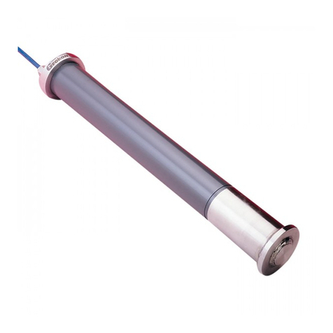
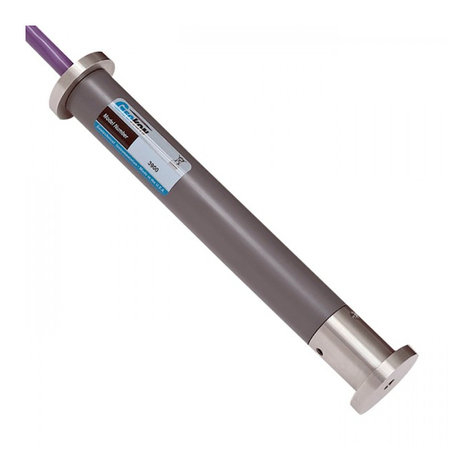
Geokon 4500HT User manual

Instruction Manual
Model 4500HT
High Temperature
Vibrating Wire Piezometer
No part of this instruction manual may be reproduced, by any means, without the written consent of Geokon, Inc.
The information contained herein is believed to be accurate and reliable. However, Geokon, Inc. assumes no responsibility for
errors, omissions, or misinterpretation. The information herein is subject to change without notification.
Copyright © 2012-2018 by Geokon, Inc.
(Doc Rev C 06/28/18)


Warranty Statement
Geokon, Inc. warrants its products to be free of defects in materials and workmanship, under
normal use and service for a period of 13 months from date of purchase. If the unit should
malfunction, it must be returned to the factory for evaluation, freight prepaid. Upon examination
by Geokon, if the unit is found to be defective, it will be repaired or replaced at no charge.
However, the WARRANTY is VOID if the unit shows evidence of having been tampered with
or shows evidence of being damaged as a result of excessive corrosion or current, heat, moisture
or vibration, improper specification, misapplication, misuse or other operating conditions outside
of Geokon's control. Components which wear or which are damaged by misuse are not
warranted. This includes fuses and batteries.
Geokon manufactures scientific instruments whose misuse is potentially dangerous. The
instruments are intended to be installed and used only by qualified personnel. There are no
warranties except as stated herein. There are no other warranties, expressed or implied, including
but not limited to the implied warranties of merchantability and of fitness for a particular
purpose. Geokon, Inc. is not responsible for any damages or losses caused to other equipment,
whether direct, indirect, incidental, special or consequential which the purchaser may experience
as a result of the installation or use of the product. The buyer's sole remedy for any breach of this
agreement by Geokon, Inc. or any breach of any warranty by Geokon, Inc. shall not exceed the
purchase price paid by the purchaser to Geokon, Inc. for the unit or units, or equipment directly
affected by such breach. Under no circumstances will Geokon reimburse the claimant for loss
incurred in removing and/or reinstalling equipment.
Every precaution for accuracy has been taken in the preparation of manuals and/or software,
however, Geokon, Inc. neither assumes responsibility for any omissions or errors that may
appear nor assumes liability for any damages or losses that result from the use of the products in
accordance with the information contained in the manual or software.


TABLE of CONTENTS
1. INTRODUCTION...................................................................................................................................................1
1.1 THEORY OF OPERATION.......................................................................................................................................1
2. CABLES...................................................................................................................................................................2
3. PRELIMINARY TESTS.........................................................................................................................................3
4. INSTALLATION IN BOREHOLES.....................................................................................................................3
5. TAKING READINGS.............................................................................................................................................3
5.1 GK-404 READOUT BOX.......................................................................................................................................3
5.1.1 Operating the GK-404 ................................................................................................................................3
5.2 GK-405 READOUT BOX.......................................................................................................................................5
5.2.1 Operating the GK-405 ................................................................................................................................5
5.3 GK-403 READOUT BOX (OBSOLETE MODEL)......................................................................................................6
5.3.1 Operating the GK-403 ................................................................................................................................6
6. DATA REDUCTION ..............................................................................................................................................7
7. TROUBLESHOOTING........................................................................................................................................15
APPENDIX A. SPECIFICATIONS.........................................................................................................................16
A.1 4500HT PIEZOMETER .......................................................................................................................................16
A.2 MINERAL INSULATED CABLE............................................................................................................................16
A.3 TUBULAR ENCAPSULATED CABLE (TEC).........................................................................................................16
APPENDIX B. 4500HT 4 MM TO 4 MM CABLE SPLICE .................................................................................17
B.1 TOOLS AND SUPPLIES........................................................................................................................................17
B.2 PROCEDURE ......................................................................................................................................................17
APPENDIX C. SWAGELOK TUBE FITTING INSTRUCTIONS......................................................................19
C.1 INSTALLATION ..................................................................................................................................................19
C.2 REASSEMBLY INSTRUCTIONS ............................................................................................................................20

FIGURES
FIGURE 1-CABLE INSIDE STAINLESS STEEL TUBING .................................................................................................... 2
FIGURE 2-STAINLESS STEEL TUBING WITH TRANSITION TO 02-250V6 CABLE ............................................................ 2
FIGURE 3-LEMO CONNECTOR TO GK-404 ................................................................................................................... 4
FIGURE 4-GK-405 READOUT BOX............................................................................................................................... 5
FIGURE 5-ATYPICAL MODEL 4700 VW TEMPERATURE SENSOR CALIBRATION REPORT............................................ 9
FIGURE 6-TYPICAL CALIBRATION REPORT AT 25 °C ..................................................................................................10
FIGURE 7-TYPICAL CALIBRATION REPORT AT 100 °C ................................................................................................11
FIGURE 8-TYPICAL CALIBRATION REPORT AT 150 °C ................................................................................................12
FIGURE 9-TYPICAL CALIBRATION REPORT AT 200 °C ................................................................................................13
FIGURE 10 -TYPICAL CALIBRATION REPORT AT 250 °C...............................................................................................14
FIGURE 11 -TUBE INSERTION.......................................................................................................................................19
FIGURE 12 -MAKE A MARK AT SIX O’CLOCK ..............................................................................................................19
FIGURE 13 -TIGHTEN ONE AND ONE-QUARTER TURNS ...............................................................................................19
FIGURE 14 -MARKS FOR REASSEMBLY ........................................................................................................................20
FIGURE 15 -FERRULES SEATED AGAINST FITTING BODY.............................................................................................20
FIGURE 16 -TIGHTEN NUT SLIGHTLY...........................................................................................................................20
TABLES
TABLE 1-STANDARD PIEZOMETER WIRING.................................................................................................................. 2
TABLE 2-HT VIBRATING WIRE PIEZOMETER SPECIFICATIONS ...................................................................................16
TABLE 3-MINERAL INSULATED CABLE SPECIFICATIONS ............................................................................................16
TABLE 4-TUBULAR ENCAPSULATED CABLE SPECIFICATIONS.....................................................................................16
EQUATIONS
EQUATION 1-PRESSURE ............................................................................................................................................... 7
EQUATION 2-TEMPERATURE........................................................................................................................................ 7
EQUATION 3-ZERO READING....................................................................................................................................... 7
EQUATION 4-GAGE FACTOR ........................................................................................................................................ 8

1
1. INTRODUCTION
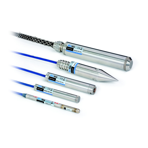
Geokon’s 4500HT Series High Temperature Piezometers are designed for monitoring downhole
pressures and temperatures in oil recovery systems and geothermal applications. Each 4500HT
pressure transducer is equipped with a Model 4700 Vibrating Wire Temperature Sensor which
gives a varying resistance output as the temperature changes.
4500HT sensors are capable of operation under extreme conditions and at temperatures up to
250 °C. In thermal recovery applications such as Steam Assisted Gravity Drainage (SAGD) and
Cyclic Steam Stimulation (CSS) they provide accurate, real-time, continuous monitoring of
pressures in production and injection wells, thereby optimizing the recovery rate and reducing
the cost of the steam injection process. In geothermal applications, they offer a means for in situ,
continuous monitoring of pressures and temperatures over extended periods of time.
1.1 Theory of Operation
Geokon vibrating wire piezometers utilize a sensitive stainless steel diaphragm to which a
vibrating wire element is connected. During use, changing pressures on the diaphragm cause it to
deflect. This deflection is measured as a change in tension and frequency of vibration in the
vibrating wire element. The square of the vibration frequency is directly proportional to the
pressure applied to the diaphragm. A filter is used to keep out solid particles and prevent damage
to the sensitive diaphragm. Standard filters are 50 micron stainless steel.
Two coils, one with a magnet insert, the other with a pole piece insert, are installed near the
vibrating wire. In use, a pulse of varying frequency (swept frequency) is applied to these coils,
causing the wire to vibrate primarily at its resonant frequency. When the excitation ends, the
wire continues to vibrate. During vibration a sinusoidal signal is induced in the coils and
transmitted to the readout box where it is conditioned and displayed. The 4500HT sensors are
designed for static measurements only; at least one second is required to excite and read the
sensor.
All exposed components are made of corrosion resistant stainless steel. If proper installation
techniques are used, the device should have an unlimited life. In salt water it may be necessary to
use special materials for the diaphragm and housing.
Portable readout units are available to provide the excitation, signal conditioning, and readout of
the instrument. Datalogging systems are also available for remote unattended data collection of
multiple sensors. Contact Geokon for additional information.

2
2. CABLES
4500HT series piezometers may be delivered with four conductor, 24-gage, Teflon® insulated
cable inside stainless steel tubing, or, four conductor, 22-gage mineral insulated cable in a
magnesium oxide jacket with 316 stainless steel sheath. (Sheath wall = 0.76 mm [0.03"].
Nominal O.D. = 4.76 mm [0.1875"]). Both cable types are delivered in coils, and can be
terminated in bare leads (Figure 1), with a connector, a transition to a regular instrumentation
cable (Figure 2), or other termination as determined by the customer. See Table 1 below for
standard wiring.
Figure 1 - Cable Inside Stainless Steel Tubing
Figure 2 - Stainless Steel Tubing with Transition to 02-250V6 Cable
Function 02-156T Cable 02-187MI Cable
Cables that transition to
02-250V6 cable
Vibrating Wire Gage +
Red
Red
Red
Vibrating Wire Gage -
Black
Black
Black
Temperature Sensor
White
White
White
Temperature Sensor
Blue
Green
Green
Cable Shield
Shield
Shield
Shield
Table 1 - Standard Piezometer Wiring

3
3. PRELIMINARY TESTS
Upon receipt of the piezometer the zero reading should be checked and noted. A Model 4700
VW Temperature Sensor is included inside the body of the sensor for the measurement of
temperature. (See Section 5 for readout instructions.)
Calibration data are supplied with each gage and zero readings at six different temperatures and
barometric pressure is included. Zero readings at the site should coincide with the calibration
zero readings within ±50 digits after barometric and temperature corrections are made. The
factory elevation is +580 ft. Before March 21, 1995 factory barometric pressure readings were
corrected to sea level; readings after this date represent absolute pressure. (Barometric pressure
changes with elevation at a rate of ≈1/2 psi per 1,000 ft.) See Section 6 for sample calibration
reports.
4. INSTALLATION IN BOREHOLES
Before installing make sure both pressure and temperature sensors are working and record initial
readings with a portable readout box (GK-403 or GK 404).
Push the sensor into the borehole by whatever means are chosen. This may include attachment to
grout pipes, special installation rods or other apparatuses being inserted into the borehole at the
same time.
5. TAKING READINGS
The 4500HT is usually connected to a datalogger, but for initial set up it is often more
convenient to use a portable readout box. When the 4500HT piezometer is connected to a
datalogger the pluck voltage must be set to 12 volts.
5.1 GK-404 Readout Box
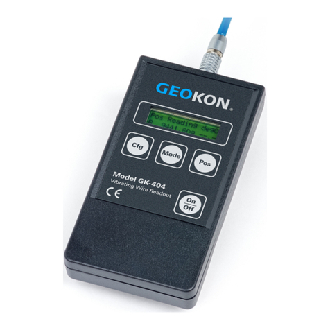
The Model GK-404 Vibrating Wire Readout is a portable, low-power, handheld unit that is
capable of running for more than 20 hours continuously on two AA batteries. It is designed for
the readout of all Geokon vibrating wire gages and transducers, and is capable of displaying the
reading in either digits, frequency (Hz), period (µs), or microstrain (µε).
5.1.1 Operating the GK-404
Before use, attach the flying leads to the GK-404 by aligning the red circle on the silver
Lemo connector of the flying leads with the red line on the top of the GK-404 (Figure 3).
Insert the Lemo connector into the GK-404 until it locks into place.

4
Figure 3 - Lemo Connector to GK-404
To turn the GK-404 on, press the “ON/OFF” button on the front panel of the unit. The
initial startup screen will displayed. After approximately one second, the GK-404 will
start taking readings and display them based on the settings of the POS and MODE
buttons.
The unit display (from left to right) is as follows:
•The current Position: Set by the POS button. Displayed as a letter A through F.
•The current Reading: Set by the MODE button. Displayed as a numeric value
followed by the unit of measure.
Use the POS button to select position Band the MODE button to select Dg (digits).
(Other functions can be selected as described in the GK-404 Manual.)
The red and black clips of the GK-404-1 flying leads are used for taking both the pressure
reading and the temperature reading. The white and green clips of the flying leads are not
used with the 4500HT. Make sure the shield drain wire is connected to the blue clip on
the flying leads for both readings.
To take a pressure reading, connect the red and black clips from the flying leads to the
red and black leads of the 4500HT.
To take a temperature reading, connect the red and black clips from the flying leads to the
white and green (or blue) leads of the 4500HT.
See Section 6 for information on Data Reduction.
The GK-404 will continue to take measurements and display readings until the unit is
turned off, either manually, or if enabled, by the Auto-Off timer. If no reading displays or
the reading is unstable see Section 7 for troubleshooting suggestions.
For further information consult the GK-404 manual.

5
5.2 GK-405 Readout Box
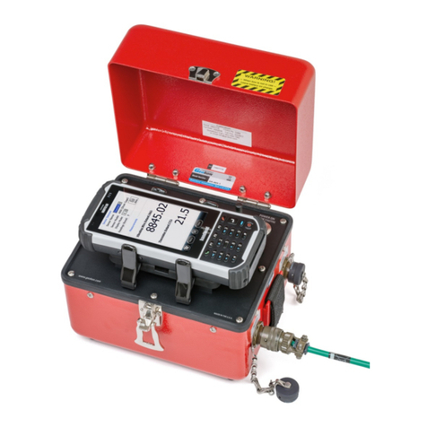
The GK-405 Vibrating Wire Readout is made up of two components: The Readout Unit,
consisting of a Windows Mobile handheld PC running the GK-405 Vibrating Wire Readout
Application; and the GK-405 Remote Module, which is housed in a weatherproof enclosure and
connects to the vibrating wire gage to be measured. The two components communicate
wirelessly using Bluetooth®, a reliable digital communications protocol. The Readout Unit can
operate from the cradle of the Remote Module, or, if more convenient, can be removed and
operated up to 20 meters from the Remote Module.
Figure 4 - GK-405 Readout Box
5.2.1 Operating the GK-405
1) Attach the GK-403-2 flying leads to the unit.
2) Press the button labeled “POWER ON (BLUETOOTH)”.
3) A blue light will begin blinking, signifying that the Remote Module is waiting to
connect to the handheld unit.
4) Launch the GK-405 VWRA program handheld PC by tapping on “Start”, then
“Programs ”, and then the GK-405 VWRA icon.
5) After a few seconds, the blue light on the Remote Module should stop flashing and
remain lit, indicating that the remote module has successfully paired with the
handheld PC.
6) The red and black clips of the GK-403-2 flying leads are used for taking both the
pressure reading and the temperature reading. The white and green clips of the flying
leads are not used with the 4500HT. Make sure the shield drain wire is connected to
the blue clip on the flying leads for both readings.
7) To take a pressure reading, connect the red and black clips from the flying leads to
the red and black leads of the 4500HT.

6
8) To take a temperature reading, connect the red and black clips from the flying leads
to the white and green (or blue) leads of the 4500HT.
9) The Live Reading window on the handheld PC will display the vibrating wire output
in digits. The last digit may change one or two digits while reading.
10)See Section 6 for information on Data Reduction.
If the no reading displays or the reading is unstable see Section 7 for troubleshooting
suggestions. For further information consult the GK-405 Instruction Manual.
5.3 GK-403 Readout Box (Obsolete Model)
The GK-403 can store gage readings and also apply calibration factors to convert readings to
engineering units. The following instructions explain taking gage measurements using Modes
“B” and “F”. Consult the GK-403 Instruction Manual for additional information.

5.3.1 Operating the GK-403
1) Attach the GK-403-2 flying leads to the unit.
2) Turn the display selector to position “B” (or “F”).
3) Turn the unit on.
4) The red and black clips of the GK-403-2 flying leads are used for taking both the
pressure reading and the temperature reading. The white and green clips of the flying
leads are not used with the 4500HT. Make sure the shield drain wire is connected to
the blue clip on the flying leads for both readings.
5) To take a pressure reading, connect the red and black clips from the flying leads to
the red and black leads of the 4500HT.
6) To take a temperature reading, connect the red and black clips from the flying leads to
the white and green (or blue) leads of the 4500HT.
7) The readout will display the vibrating wire output in digits. The last digit may change
one or two digits while reading.
8) Press the “Store” button to record the value displayed.
9) See Section 6 for information on Data Reduction.
If the no reading displays or the reading is unstable see Section 7 for troubleshooting
suggestions.
The unit will automatically turn off after approximately two minutes to conserve power.

7
6. DATA REDUCTION
Each Model 4500HT pressure transducer is supplied with a calibration report showing the output
of the temperature sensor at six different temperatures, ranging from room temperature to 250 °C
(Figure 5). Also supplied are five calibration reports from the pressure transducer showing the
output readings versus pressure change at five temperature intervals (Figure 6 through Figure
10).
The Model 4500HT pressure transducer and incorporated Model 4700 temperature sensor both
operate on the vibrating wire principle. The output of the temperature sensor will yield the
operating temperature directly using a second order polynomial. Calculation of pressure is not
direct. The effect of the ambient temperature on both the zero reading and gage factor must be
taken into account. In essence the data interpretation proceeds as follows, using second order
polynomials for greater accuracy.
To calculate the pressure (P) from any current reading (R1) on the pressure transducer, complete
the following:
1) Calculate the temperature (T) from the VW temperature sensor using the output reading (RT)
from the temperature sensor and the polynomial expression shown on the temperature gage
calibration report.
2) Use the temperature values and the zero pressure readings shown on the six calibration
reports in an Excel spreadsheet to develop a polynomial that describes how the zero reading
(R0) varies with the temperature. (This polynomial will be supplied along with the calibration
reports.)
3) Use the temperature values and linear gage factors shown on the six calibration reports in an
Excel spreadsheet to develop a polynomial that describes how the gage factor (G) varies with
the temperature. (This polynomial will be supplied along with the calibration reports.)
4) Using the calculated polynomial values of R0and G at the measured temperature (T) and
with the current reading (R1) find the pressure (P) from the equation:
P = (R1- R0) G
Equation 1 - Pressure
An example using an Excel Spreadsheet and the Chart Wizard Trendlines, as well as the data
from the sample Model 4700 temperature calibration report (Figure 5) and the five sample
pressure calibration reports (Figure 6 through Figure 10) is shown below.
Temperature (T) = 3.7511E-07 RT2+ 0.03484 RT-124.98
Equation 2 - Temperature
Zero Reading (R0) = -0.00193T2+ 1.885T + 8367
Equation 3 - Zero Reading

8
Gage Factor (G) = -8.61E-11T2– 2.038E-09T - 0,0002246
Equation 4 - Gage Factor
For example, suppose that the reading on the temperature sensor (RT) is 8400 and the reading on
the pressure transducer (R1) is 6500.
Then;
Temperature = 194.1 °C
Zero Reading = 8660
Gage Factor = -0.0002282
From which Pressure = (6500 – 8660) (-0.002282) = 0.493 MPa

9
Figure 5 - A Typical Model 4700 VW Temperature Sensor Calibration Report

10
Figure 6 - Typical Calibration Report at 25 °C

11
Figure 7 - Typical Calibration Report at 100 °C

12
Figure 8 - Typical Calibration Report at 150 °C

13
Figure 9 - Typical Calibration Report at 200 °C

14
Figure 10 - Typical Calibration Report at 250 °C
Other manuals for 4500HT
1
Table of contents
Other Geokon Measuring Instrument manuals

Geokon
Geokon 4200 Series User manual

Geokon
Geokon 4911A User manual

Geokon
Geokon 4427 User manual

Geokon
Geokon 1100 User manual

Geokon
Geokon 1300 User manual

Geokon
Geokon 4500 Series User manual

Geokon
Geokon 6101 User manual

Geokon
Geokon 6350 User manual

Geokon
Geokon 4500 Series User manual

Geokon
Geokon 4415 User manual