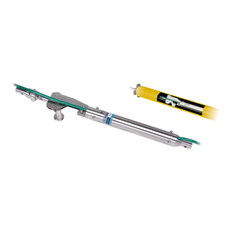
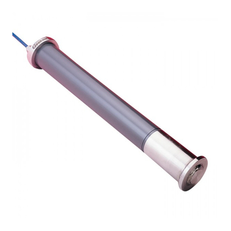
Geokon 1900 User manual

Instruction Manual
Model 1900
Magnetic Extensometer
No part of this instruction manual may be reproduced, by any means, without the written consent of Geokon, Inc.
The information contained herein is believed to be accurate and reliable. However, Geokon, Inc. assumes no responsibility for
errors, omissions, or misinterpretation. The information herein is subject to change without notification.
Copyright © 1994-2018 by Geokon, Inc.
(Doc Rev H, 04/25/18)


Warranty Statement
Geokon, Inc. warrants its products to be free of defects in materials and workmanship, under
normal use and service for a period of 13 months from date of purchase. If the unit should
malfunction, it must be returned to the factory for evaluation, freight prepaid. Upon examination
by Geokon, if the unit is found to be defective, it will be repaired or replaced at no charge.
However, the WARRANTY is VOID if the unit shows evidence of having been tampered with
or shows evidence of being damaged as a result of excessive corrosion or current, heat, moisture
or vibration, improper specification, misapplication, misuse or other operating conditions outside
of Geokon's control. Components which wear or which are damaged by misuse are not
warranted. This includes fuses and batteries.
Geokon manufactures scientific instruments whose misuse is potentially dangerous. The
instruments are intended to be installed and used only by qualified personnel. There are no
warranties except as stated herein. There are no other warranties, expressed or implied, including
but not limited to the implied warranties of merchantability and of fitness for a particular
purpose. Geokon, Inc. is not responsible for any damages or losses caused to other equipment,
whether direct, indirect, incidental, special or consequential which the purchaser may experience
as a result of the installation or use of the product. The buyer's sole remedy for any breach of this
agreement by Geokon, Inc. or any breach of any warranty by Geokon, Inc. shall not exceed the
purchase price paid by the purchaser to Geokon, Inc. for the unit or units, or equipment directly
affected by such breach. Under no circumstances will Geokon reimburse the claimant for loss
incurred in removing and/or reinstalling equipment.
Every precaution for accuracy has been taken in the preparation of manuals and/or software,
however, Geokon, Inc. neither assumes responsibility for any omissions or errors that may
appear nor assumes liability for any damages or losses that result from the use of the products in
accordance with the information contained in the manual or software.

TABLE of CONTENTS
1. INTRODUCTION .................................................................................................................................................. 1
1.1 THEORY OF OPERATION...................................................................................................................................... 1
2. INSTALLATION.................................................................................................................................................... 3
2.1 LIST OF SUGGESTED TOOLS ................................................................................................................................ 3
2.2 INSTALLATION IN BOREHOLES ............................................................................................................................ 3
2.2.1 Preparing the Access Tube Anchor String ................................................................................................. 3
2.2.2 Installing the Access Tube Anchor String................................................................................................... 4
2.3 INSTALLATION IN FILLS ...................................................................................................................................... 5
3. TAKING READINGS............................................................................................................................................ 6
4. DATA REDUCTION.............................................................................................................................................. 6
APPENDIX A. SPECIFICATIONS.......................................................................................................................... 7
APPENDIX B. BATTERY REPLACEMENT......................................................................................................... 8
FIGURES
FIGURE 1-TYPICAL MAGNETIC EXTENSOMETER INSTALLATIONS................................................................................ 1
FIGURE 2-ANCHOR ASSEMBLY /SECURING THE LEAF SPRINGS................................................................................... 4
FIGURE 3-TAPE GUIDE MOUNTED TO ACCESS TUBE ................................................................................................... 5
FIGURE 4-UNDERSIDE OF REEL FLANGE ...................................................................................................................... 8
FIGURE 5-CLOSE UP OF THE NINE-VOLT BATTERY...................................................................................................... 8
TABLES
TABLE 1-MODEL 1900 SPECIFICATIONS....................................................................................................................... 7

1
1. INTRODUCTION
The Model 1900 Magnetic Extensometer is designed to measure movement between magnetic
targets anchored in the ground. It is normally installed in a borehole or directly in fill as it is
placed. The primary use of the Magnetic Extensometer is the measurement of vertical
compression in embankments, foundations, and fills and the movement of settlements in soft
ground due to the placement of fills and embankments. It may also be used to measure heave.
1.1 Theory of Operation
Figure 1 shows the basic arrangement of the Magnetic Extensometer.
Top Cap
Telescoping Coupling
with O-ring Seals
Flush Coupled
Access Tube
(or Inclinometer Casing)
Datum Magnets
Borehole Installation
Manhole
with Cover
End Cap
(mechanically released)
Spider Magnet
Spider Magnet
Soft Bentonite Grout
Protective Cover
Top Cap
Plate Magnet
Telescoping Coupling
with O-ring Seals
Fill
Flush Coupled
Access Tube
(or Inclinometer Casing)
Datum Magnets
Installation in Fill
End Cap
Cable Reel
with Audible
Nylon Coated Steel Tape
Reed Switch Probe
(push-in type)
Figure 1 - Typical Magnetic Extensometer Installations

2
Anchor points with permanent magnets are anchored in the ground with a continuous access tube
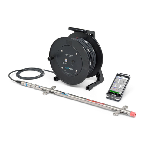
passing through their center. A reed switch probe is lowered inside the access tube on the end of
a graduated measurement tape, which also contains two electrical conductors. As the probe
passes each anchor, the magnets in the anchor cause the reed switch to close, this sounds a
buzzer on the tape reel at the surface.
When the buzzer sounds the depth of the anchor is measured by reading the graduated tape
opposite the top of the access tube.
In most cases, the bottom of the access tube is deep enough to be located in solid ground. A
datum magnet anchored to the bottom of the access tube provides a stable benchmark datum to
which all the other anchor measurements are referred to in order to calculate the absolute
settlement of each anchor point relative to the benchmark.
If the bottom of the access tube cannot be located in the solid ground then it will be necessary to
reference the position of each anchor to the top of the access tube and to transfer this elevation to
an external benchmark by normal level surveying techniques.

3
2. INSTALLATION
2.1 List of Suggested Tools
•Black electrical tape (securing pull pins, packing pull cables, to protect loops)
•Masking tape (to hold pull cables during installation)
•Small cutting tool (to cut cable ties)
•Measuring tape (to place the anchors on the access tube at correct depth)
•Pen of Marker (to identify anchor location on access tube)
•PVC glue (for bottom cap)
•Steel saw (to cut access tubing)
•Long pushrod, typically threaded water pipe (extensible to reach the bottom of the hole)
•Color tapes to identify pull cables (or ID numbers)
•Small and medium plastic cable ties or cable clamps/grips (for making loops with the cable)
•Medium cutting tool (to cut pull cable)
•Small cutting tool (to cut cable ties)
•Measuring tape (to place the anchors on the access tube at correct depth)
•300 ft. tape (to measure pull cable length)
•Working gloves (to hold anchor legs closed when working with the chain and the access
tube)cable
•Grease for telescopic sections (and possibly for anchors)
•Clear water (to clean threads)
•Pipe wrench (for threaded water pipe)
2.2 Installation in Boreholes
Boreholes may be open, cased, grouted, or not grouted. In cased boreholes, it will be necessary
to pull the casings after the string of access tubes and anchors have been installed inside it. In
holes that are to be grouted using a soft bentonite grout there are two options: a) to pre-grout the
borehole or b) to grout the borehole through a tremie pipe after the extensometer string has been
lowered into position.
2.2.1 Preparing the Access Tube Anchor String
It is advisable to prepare the entire access tube string on a stretch of clean, level ground
prior to installing it. In this way, there will be a minimum of delay during the actual
installation since everything will be ready. Do not screw the sections together; just
arrange them in their correct order with the anchors attached.
1) Begin by cementing the end cap onto the bottom section of the access tubing using
PVC cement (not supplied by Geokon).
2) Using three set screws, tighten the datum magnet onto the bottom section of the
access tube about one meter above the bottom end cap. (Do not put the datum magnet
too close to the bottom in case the access tube silts up.)

4
3) Select further sections of access tube and/or telescoping couplings. Position the spider
anchors along the sections of access tubing in their desired locations. The spider
anchors are attached to the access tube as shown in Figure 2.
Figure 2 - Anchor Assembly / Securing the Leaf Springs
4) Use the chains supplied to restrain the ends of the leaf springs). The pull-pin passes
though the links of the chain holding the leaf springs snug against the access tube. Use
3/4 inch electricians tape (two turns) around the pull pin above and below the anchor,
(see Figure 2). This holds the anchor pull-pin in place and makes it more difficult to
pull the pin out, thus reducing the risk of prematurely tripping the anchor during
installation.) It also holds the spider anchor in place preventing it from sliding up the
access tube during installation.
5) Leaving the pull cable coiled, connect the loop on the end of the cable to the anchor
pull-pin by clipping the hook through the eye of the pull cable.
6) Wrap a single layer of masking tape around the cable about 30 cm above the hook.
This also will make it difficult for the pull-pin to be pulled prematurely.
7) Tape identification tags onto each end of the pull cables, e.g., use “#1” for the top
anchor, “#2” for the next anchor, etc. Colored tapes can tapes can also be used for
identification if identification tags are not available.
2.2.2 Installing the Access Tube Anchor String
1) Begin assembling the access tube string and pushing it into the borehole. If the hole is
to be grouted after the string is placed, then the tremie pipe should be taped to the end
of the access tube. Tape heavily enough to prevent the Tremie pipe from coming
loose as it is pushed into the hole but not so heavy that it cannot be pulled loose
deliberately at the start of grouting. If the borehole is already filled with grout or
water, it will be necessary to fill the access tube with water to overcome the buoyancy
forces.
2) When sections with spider anchors are added to the string, the pull-cables should be
uncoiled and fed smoothly into the borehole along with the access tubing. Do not
allow any of the pull-cables be snagged, tangled, or pulled on, which could cause
premature triggering of the anchors. It may be advisable to have more than one
person in charge of the pull-cables and tremie pipe.
3) Once the access tube has been lowered to the bottom of the borehole, it will be
necessary to make sure that all the telescoping couplings are fully extended to
accommodate the anticipated settlements. (If heave is being measured, the couplings

5
can be left closed or nearly closed.) This is best done by means of a long push rod
(not supplied by Geokon) made from any easily available water pipe with threaded
connectors. The push rod assembly when joined should be sufficient length to reach
the bottom of the access tube. To open the telescopic couplings push down on the
push rod assembly and pull up on the access tubes.
4) Use the reed switch probe to verify the position of the anchors before they have been
tripped. (See Section 3 for information on taking readings.) If the anchors have
slipped it is still possible to remove the access tube and reposition them.
5) If the hole is to be grouted, it should be done at this time. Bentonite grout of the type
that will remain soft and not impede the settlement of the ground (i.e., grout that will
allow the anchor to follow the movement of the ground) should be used. (A typical
grout is 43 kgm cement, 2 kgm bentonite and 40 kgm water, or enough water to make
the mix thin enough to pump.)
6) If the hole is cased the casing can now be removed. Make sure that the access tubing
does not pull upwards during this process.
7) The magnetic spider anchors can now be released beginning at the top anchor. Select
pull-cable #1 and give it a quick hard pull.
8) Remove the pull-cable and anchor pull-pin completely from the borehole before
tripping anchor #2. Repeat this process for all the anchors.
9) Install the plastic tape guide by sliding the access tube into the slots in the guide (see
Figure 3).
Figure 3 - Tape Guide Mounted to Access Tube
2.3 Installation in Fills
Plate shaped magnetic anchors are used in fills. As the fill is placed the access tube is extended
upwards by screwing on more sections along with telescoping couplings (make sure these are
fully extended when installed). The plate anchors are laid on top of the fill surface as soon as it
reaches the desired anchor elevation. They are then buried as more fill is placed.
Each new section of access tube that is added will alter the reed switch probe readings; however,
the data reduction will still follow the method outlined in Section 4.

6
3. TAKING READINGS
Before taking readings, check the battery voltage by depressing the “TEST” button on the side of
the tape storage reel; if no beep is heard the nine-volt alkaline battery needs to be replaced. (See
Appendix B for battery replacement instructions.) Access to the battery holder is made by
removing the three small screws around the periphery of the tape reel on the side that holds the
test button and buzzer.
Readings are taken by lowering the reed switch probe down the access tube until an audible beep
is heard from the buzzer in the tape reel. A reading of the graduated measurement tape is taken
opposite the top of the access tube when the buzzer just starts to sound.
For greater accuracy, a second reading can be obtained at the same anchor by lowering the probe
until the buzzer stays beeping. Take a measurement on the tape, as before, and average the two
readings to get the position of the anchor.
Repeat this process for all the anchors and the datum anchor at the bottom of the hole.
4. DATA REDUCTION
The distance from the datum magnet to the top of the access tube can be designated Dtmeters .
The distance from the top of the access tube to any intermediate anchor can be designated D1,
D2, D3, etc.
If the datum magnet is located in solid ground (i.e., no settlement) then the true settlement of any
intermediate anchor is given by Dt- Dnmeters.
For instance, assume that initially Dt= 29.214 meters and the measured distance to the top
anchor D1is 3.632 meters.
Then (Dt-D1) at time T0is 25.582 meters.
One day later at time T1, Dt= 28.943 meters and D1=3.595 meters. (Dt-D1) at time T1is 25.348
meters, hence anchor D1has settled (25.582-25.348) = 0.234 meters. Similarly, the top of the
access tube has settled a distance of (29.214-28.943) = 0.271 meters and the compression of the
ground between the top of the access tube and anchor D1is (0.271-0.234) = 0.037 meters.
If, on the other hand, it is required that all measurements be referred to the top of the access tube,
then the actual elevation of the borehole anchors can be computed by subtracting the measured
distances D1, D2, D3, etc. from the surveyed elevation of the top of the access tube. The
settlement of each anchor is then the observed difference of elevation from one survey to the
next.

7
APPENDIX A. SPECIFICATIONS
Cable Lengths:
Metric Cable Lengths 30 m, 100 m, 150 m, 200 m
Standard cable lengths 100 ft., 125 ft., 200 ft., 300 ft.
Resolution:
±1 mm (±0.04")
Repeatability:
±3 mm (±0.12")
Temperature Range:1
−30 to +80° C
-30 to 110° F
Probe Construction:
Stainless Steel and Delrin
Probe Dimensions (L x ∅):
178 ⨉19 mm (7" ⨉0.75")
Access Tube:
33 mm (1.3") O.D. Sch. 80 PVC
Telescoping Section:
1 m (3.28 ft.)
Fully compressed: 460 mm (18.1")
Telescoping Section
Range of movement:
300 mm
(11.8")
Plate Magnet Material:
PVC
Plate Magnet Dimensions:
(L ⨉W ⨉D)
300 mm ⨉300 mm ⨉9.5 mm
(11.8" ⨉11.8" ⨉0.37")
Spider Magnet Material:
Body: PVC
Legs: Hardened 17-7 SS
Spider Magnet Dimensions:
(L ⨉O.D. ⨉I.D.)
Closed: 445 ⨉70 ⨉34 mm (17.5" ⨉2.75" ⨉1.34")
Released: 445 ⨉203 ⨉34 mm (17.5" ⨉8" ⨉1.34")
Leaf Spring (Spider Leg) Stiffness:
> 20N
Datum Magnet Material:
PVC
Datum Magnet Dimensions:
54 ⨉60 ⨉34 mm (2.13" ⨉2.36" ⨉1.34")
Borehole Size:²
102-152 mm (4-6")
Power:
9V Alkaline Battery
Table 1 - Model 1900 Specifications
Notes:
¹ Other ranges available on request
² Other sizes available

8
APPENDIX B. BATTERY REPLACEMENT
To replace the battery, remove the three screws on the buzzer side flange of the reel. Remove the flange,
being careful not to not allow the tape to fall off the reel while doing so. Replace the nine-volt battery
with a new one. (See Figure 4and Figure 5for battery location. Make sure the + and - sides of the
battery are in the correct positions. Reinstall the flange and the screws.
Figure 4 - Underside of Reel Flange
Figure 5 - Close up of the Nine-Volt Battery
Table of contents
Other Geokon Measuring Instrument manuals

Geokon
Geokon GK-406 User manual

Geokon
Geokon 4675LV User manual

Geokon
Geokon 6165 User manual

Geokon
Geokon 4200ER User manual

Geokon
Geokon 1100 User manual

Geokon
Geokon 4700 User manual

Geokon
Geokon 4200 Series User manual

Geokon
Geokon GK-405 User manual

Geokon
Geokon 4425 User manual

Geokon
Geokon 4300 Series User manual
Popular Measuring Instrument manuals by other brands

Crosby
Crosby SP Handheld Plus operating instructions

Fluke
Fluke 165X Quick reference guide

Absolute Process Instruments
Absolute Process Instruments Cecomp F20B quick start guide

Leica
Leica Disto X310 Assembly manual

Huato
Huato A2000 Series Operation manual

Sierra
Sierra InnovaSonic 210 Quick install guide