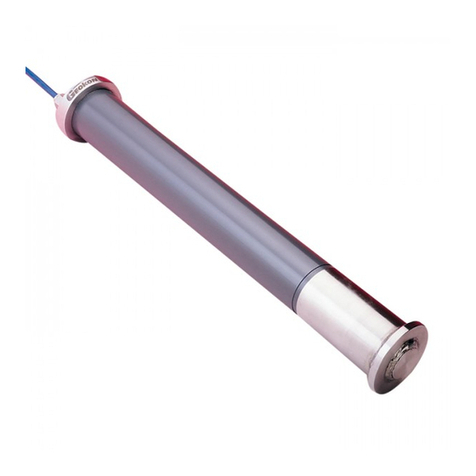
Geokon 6150F User manual

©2019, GEOKON. All rights reserved.
Document Revision: Init | Release date: 8/6/19
Model 6150F
MEMS Digital Addressable
In-Place Inclinometer
Instruction Manual


WARRANTY STATEMENT
GEOKON warrants its products to be free of defects in materials and workmanship,
under normal use and service for a period of 13 months from date of purchase. If the
unit should malfunction, it must be returned to the factory for evaluation, freight
prepaid. Upon examination by GEOKON, if the unit is found to be defective, it will be
repaired or replaced at no charge. However, the WARRANTY IS VOID if the unit shows
evidence of having been tampered with or shows evidence of being damaged as a
result of excessive corrosion or current, heat, moisture or vibration, improper specifi-
cation, misapplication, misuse or other operating conditions outside of GEOKON's
control. Components that wear or are damaged by misuse are not warranted. This
includes fuses and batteries.
GEOKON manufactures scientific instruments whose misuse is potentially dangerous.
The instruments are intended to be installed and used only by qualified personnel.
There are no warranties except as stated herein. There are no other warranties,
expressed or implied, including but not limited to the implied warranties of merchant-
ability and of fitness for a particular purpose. GEOKON is not responsible for any
damages or losses caused to other equipment, whether direct, indirect, incidental,
special or consequential which the purchaser may experience as a result of the instal-
lation or use of the product. The buyer's sole remedy for any breach of this agreement
by GEOKON or any breach of any warranty by GEOKON shall not exceed the purchase
price paid by the purchaser to GEOKON for the unit or units, or equipment directly
affected by such breach. Under no circumstances will GEOKON reimburse the
claimant for loss incurred in removing and/or reinstalling equipment.
Every precaution for accuracy has been taken in the preparation of manuals and/or
software, however, GEOKON neither assumes responsibility for any omissions or
errors that may appear nor assumes liability for any damages or losses that result
from the use of the products in accordance with the information contained in the
manual or software.
No part of this instruction manual may be reproduced, by any means, without the written consent of GEOKON. The
information contained herein is believed to be accurate and reliable. However, GEOKON assumes no responsibility
for errors, omissions or misinterpretation. The information herein is subject to change without notification.
The GEOKON® wordmark and logo are registered trademarks with the United States Patent and Trademark Office.


1
TABLE OF CONTENTS
1. INTRODUCTION............................................................................................................................................1
2. INSTALLATION..............................................................................................................................................2
2.1 PRELIMINARY TESTS ......................................................................................................................2
2.2 ASSEMBLY ................................................................................................................................................3
2.2.1 SEGMENT ASSEMBLY ...................................................................................................................3
2.2.2 BOTTOM WHEEL ASSEMBLY ......................................................................................................3
2.2.3 SENSOR ORIENTATION ..................................................................................................................4
2.2.4 SENSOR INSTALLATION ................................................................................................................5
2.2.5 CONNECTING THE SUSPENSION BRACKET .........................................................................5
2.3 MODEL 8020-38 RS-485 TO TTL/USB CONVERTER............................................6
2.4 SIX-PIN WATERPROOF CONNECTOR...............................................................................7
3. MODBUS RTU PROTOCOL ..............................................................................................................8
3.1 INTRODUCTION TO MODBUS..................................................................................................8
3.2 MODBUS RTU OVERVIEW ...........................................................................................................8
3.3 MODBUS TABLES ...............................................................................................................................8
4. DATA REDUCTION ................................................................................................................................11
4.1 INCLINATION CALCULATION............................................................................................... 11
4.2 DEFLECTION CALCULATION ................................................................................................. 11
4.3 TEMPERATURE CORRECTION ............................................................................................. 12
4.4 ENVIRONMENTAL FACTORS ................................................................................................ 12
5. TROUBLESHOOTING .......................................................................................................................... 13
APPENDIX A. SPECIFICATIONS .................................................................................................. 15
A.1 PARTS LIST .......................................................................................................................................... 15
APPENDIX B. SAMPLE CALIBRATION SHEETS ....................................................... 16
APPENDIX C. MODBUS ADDRESSABLE SYSTEM ................................................ 18
C.1 MODBUS COMMUNICATIONS PARAMETERS..................................................... 18
C.2 ERROR CODES ................................................................................................................................... 18
APPENDIX D. CRBASIC PROGRAMMING........................................................................ 19
D.1 SAMPLE CR1000 PROGRAM ............................................................................................... 19
D.2 SAMPLE CR6 PROGRAM ......................................................................................................... 19
APPENDIX E. DROPS VERSUS LENGTH............................................................................ 21

1
FIGURES
FIGURE 1: MODEL 6150F INSTALLED .............................................................................1
FIGURE 2: CABLE CONNECTION DETAIL ........................................................................2
FIGURE 3: CONNECTED CABLES .....................................................................................2
FIGURE 4: END TERMINATOR MODEL 6150F-2 .............................................................2
FIGURE 5: CONNECT THE SEGMENT ASSEMBLY ..........................................................3
FIGURE 6: 6300-7 TUBE COUPLING ................................................................................3
FIGURE 7: CONNECT THE BOTTOM WHEEL ASSEMBLY ...............................................4
FIGURE 8: CONNECT THE SAFETY CABLE ......................................................................4
FIGURE 9: A & B DIRECTIONS ..........................................................................................4
FIGURE 10: CABLE CONNECTION DETAIL ......................................................................5
FIGURE 11: SUSPENSION VIA CABLE .............................................................................5
FIGURE 12: SUSPENSION VIA TUBE ...............................................................................5
FIGURE 13: MODEL 8020-38 TTL/USB TO RS-485 CONVERTER ...................................6
FIGURE 14: WIRING OF DATALOGGER WITHOUT BUILT-IN RS-485 CONVERSION ...6
FIGURE 15: WIRING OF DATALOGGER WITH RS-485 CONVERSION ...........................6
FIGURE 16: MALE WATERPROOF CONNECTOR ............................................................7
FIGURE 17: FEMALE WATERPROOF CONNECTOR ........................................................7
FIGURE 18: DEFLECTION INTERVALS ...........................................................................11
FIGURE 19: SAMPLE MODEL 6150F CALIBRATION SHEET, SENSOR A ....................16
FIGURE 20: SAMPLE MODEL 6150F CALIBRATION SHEET, SENSOR B ....................17
FIGURE 21: ALLOWED DROPS GRAPHIC REPRESENTATION .....................................21

1
TABLE S
TABLE 1: SIX-PIN WIRING CHART.................................................................................... 7
TABLE 2: REGISTER ADDRESSES AND FORMATS......................................................... 9
TABLE 3: DEVICE CONTROL ADDRESSES....................................................................... 9
TABLE 4: NON-VOLATILE MEMORY................................................................................. 9
TABLE 5: PREPROGRAMMED DEVICE INFORMATION ............................................... 10
TABLE 6: MODEL 6150F INCLINOMETER SPECIFICATIONS....................................... 15
TABLE 7: MODEL 6150F INCLINOMETER PARTS LIST................................................ 15
TABLE 8: MODBUS COMMUNICATIONS PARAMETERS ............................................. 18
TABLE 9: ERROR CODES ................................................................................................. 18

1
EQUATIONS
EQUATION 1: CORRECTED INCLINATION ANGLE.........................................................11
EQUATION 2: CHANGE IN INCLINATION .......................................................................11
EQUATION 3: LATERAL DISPLACEMENT........................................................................11
EQUATION 4: OFFSET CALCULATION.............................................................................11
EQUATION 5: DEFLECTION CALCULATION....................................................................12

MODEL 6150F MEMS DIGITAL ADDRESSABLE IN-PLACE INCLINOMETER | INTRODUCTION | 1
1. INTRODUCTION
The GEOKON Model 6150F MEMS Digital Addressable In-Place Inclinometer
system enables long-term monitoring of deformations in structures such as
dams, embankments, foundation walls, and similar applications. The basic
principle of operation is the use of tilt sensors to make accurate measurement of
inclination, over segments of a borehole, which is drilled into the structure being
studied. The instrument is designed to be installed in standard grooved
inclinometer casing, which is installed in the borehole. Constant monitoring by
the instrument allows for very precise measurement of changes in the borehole
profile. Each tilt sensor is individually serialized and calibrated. A calibration
sheet for each sensor is provided, showing the relationship between sensor
output and inclination.
Each tilt sensor is comprised of two addressable Micro-Electro-Mechanical
Systems (MEMS) devices inside a sealed stainless steel housing. The devices
measure the A and B axes of the borehole. Each sensor also contains a
thermistor for reading temperatures.
The tilt sensors are connected to each other using four-wire bus cable. Each
sensor has a length of this cable exiting both the top and bottom of the housing.
A male connector is attached to the cable exiting the top of the sensor and a
female connector is attached to the cable exiting the bottom of the sensor.
The uppermost sensor of the string connects to a customer-specified terminator
for attaching to the chosen readout (PC, datalogger, SCADA system, etc.).
The inclinometer system uses stainless steel tubing to mechanically connect the
sensors, as well as to fix them at the customer-designated intervals. The tilt
sensor housing has a wheel assembly and universal joint on its upper end. This
centralizes the sensors in the casing, allows unimpeded relative movement of
the spacer tubing, and accommodates any spiraling of the casing. The entire
string is normally supported from the top of the casing by a suspension bracket.
FIGURE 1: Model 6150F Installed

2| INSTALLATION | GEOKON
2. INSTALLATION
2.1 PRELIMINARY TESTS
Prior to installation, check the sensors for proper operation. Complete the
following steps:
1. Place the sensors in the correct order by referring to the labels on the
sensors and the provided paperwork.
2. Connect the sensors by plugging the cable exiting the underside of one
sensor into the cable exiting the top of the next sensor.
FIGURE 2: Cable Connection Detail
Caution! When connecting the sensors, make sure to line up the two nubs
on the outside of the female connector with the nub on the outside of the
male connector. This will ensure that the pins and holes on the interior of
the connectors align correctly. Push the male and female connectors
together until they are completely mated.
FIGURE 3: Connected Cables
3. Once all sensors have been connected, plug the end terminator into the
female connector at the bottom sensor. See the figure below.
FIGURE 4: End Terminator Model 6150F-2
4. Connect the completed string to a readout or datalogger.
5. Hold the first sensor in a vertical position and observe the reading. The tilt
sensor must be held steady while taking the reading. The observed reading
should be close to the factory vertical reading. Tilts in a positive direction
(A+ or B+, as marked on the sensor) should yield increasing readings. Tilts
in a negative direction (A- or B-) should yield decreasing readings. The
temperature indicated on the readout should be close to ambient. Repeat
this process with the remaining sensors.
6. Once the preliminary tests are complete, disconnect the string from the
readout.
7. Disconnect all of the sensor cables. (The end terminator may remain on the
bottom sensor.)
Should any of these preliminary tests fail, see Section 5 for
troubleshooting.

MODEL 6150F MEMS DIGITAL ADDRESSABLE IN-PLACE INCLINOMETER | INSTALLATION | 3
2.2 ASSEMBLY
2.2.1 SEGMENT ASSEMBLY
Each tilt sensor is supplied with fasteners attached, and with a connecting tube
unattached. To complete the assembly of each segment, do the following:
1. Remove the nut/bolt fasteners from the tilt sensor.
2. Connect the spacer tube to the connector at the bottom of the tilt sensor.
3. Fasten the tube to the sensor using the nuts/bolts removed in step 1.
4. Repeat steps 1-3 for each tilt sensor/spacer tube set.
FIGURE 5: Connect the Segment Assembly
PLEASE NOTE:
□The one-inch cap screws used in the assembly procedure are installed in the
connecting tubes at the factory and must be removed before attaching the
tubing.
□The string will ship with a few spare cap screws and nuts. The shorter 3/8"
cap screws are spares for the screws that attach the wheel assemblies.
□Where the spacing of the sensors is too long for a continuous length of
tubing, connect two tubes together using the 6300-7 Tube Coupling (see
the figure below). Use the one-inch cap screws and nuts to secure this
connection.
FIGURE 6: 6300-7 Tube Coupling
□Use Loctite 222 thread locking compound on all threaded
connections.
2.2.2 BOTTOM WHEEL ASSEMBLY
The bottom wheel assembly, Model 6300-5, has no universal joint, only a swivel.
Attach this wheel assembly to the bottom segment using the provided
hardware.
Connecting Tube Tilt Sensor
Tube Coupling Connecting TubeConnecting Tube

4| INSTALLATION | GEOKON
FIGURE 7: Connect the Bottom Wheel Assembly
Note: Remember to use Loctite 222 on all threaded connections.
Attaching a safety cable to the bottom wheel assembly is strongly
recommended. Not only can it be used to retrieve the assembly if one of the
joints breaks loose, but it is also very helpful when lowering the assembly into
the casing.
Safety cables purchased from GEOKON will have an eye bolt on one end. Slide
the eye bolt onto the 10-32 cap screw used to attach the bottom segment to the
bottom wheel assembly. Tighten another nut onto the cap screw; this will trap
the safetycable between the two nuts. The completed bottom wheel assembly
is shown in the figure below.
FIGURE 8: Connect the Safety Cable
2.2.3 SENSOR ORIENTATION
All wheel assemblies should be oriented in the same direction when installed in
the casing. The wheel assemblies are attached at the factory so that the fixed
wheel is facing the A+ direction of the sensor (as shown in the figure to the left).
It is customary and recommended to point the A+ (fixed wheel) direction in the
same direction as the anticipated movement, i.e., towards the excavation being
monitored or downslope for slope stability applications.
A second MEMS device is included in the sensor and is attached with its
positive direction 90° clockwise from the first device. This is the B+ direction of
the sensor.
Bottom Wheel Assembly
Tilt Sensor
Wheel Assembly
Swivel
Bottom
Segment
Safety Cable
Cable Eye Bolt
Secured Between Two Nuts
FIGURE 9: A & B Directions
A- Direction
B+ Direction A+ Direction
B- Direction
Wheel
Assembly Fixed Wheel

MODEL 6150F MEMS DIGITAL ADDRESSABLE IN-PLACE INCLINOMETER | INSTALLATION | 5
2.2.4 SENSOR INSTALLATION
1. Insert the bottom wheel assembly into the casing, making sure to orient the
fixed wheel correctly (see Section 2.2.3).
2. Using the safety cable, lower the bottom segment into the casing hole, until
the bottom sensor is at the top of the casing.
3. Hold the segment in place at the top of the casing using vice-grips or a
similar method.
4. Plug the male connector of the bottom sensor into the female connector of
the sensor above it.
Caution! When connecting the sensors, make sure to align the two nubs
on the outside of the female connector with the nub on the outside of the
male connector. This will ensure that the pins and holes on the interior of
the connectors align correctly. Push the male and female connectors
together until they are completely mated.
FIGURE 10: Cable Connection Detail
5. Tape the signal cable to the tubing, if desired. The connectors may be taped
together for additional security.
6. Using the safety cable, lower the bottom segment into the hole, until the
next sensor is at the top of the casing. Make sure to orient the A+ direction
of the sensor correctly when inserting it into the casing.
7. Continue to add segments to the string. Connect the sensor cables together
and lower the string into the casing, until the uppermost sensor is aligned
with the top of the casing.
2.2.5 CONNECTING THE SUSPENSION BRACKET
Attach the suspension bracket to the top sensor’s wheel assembly via one of
two methods: use a cable (sold separately), or use the connector tube provided.
FIGURE 12: Suspension via Tube
FIGURE 11: Suspension via Cable
Eye Bolt
Eye Bolt
150 mm
above ground level
Below ground
Casing
Connector
Tube
Suspension
Bracket

6| INSTALLATION | GEOKON
Lower the final sensor into the casing and position the suspension bracket on
top of the casing. It is important that the top rim of the casing be relatively
square to prevent any side interference with the wheel assembly of the top
sensor.
The safety cable can now be tied off at the top of the casing and the signal cable
can be run to the readout location. Readings can be taken immediately after
installation, but it is recommended that the system be allowed to stabilize for a
few hours before recording the zero readings.
2.3 MODEL 8020-38 RS-485 TO TTL/USB CONVERTER
GEOKON makes the Model 8020-38 Addressable Bus Converter for connecting
addressable strings to personal computers, readouts, dataloggers, and
programmable logic controllers. The converter acts as a bridge using the TTL or
USB protocols between readers and the GEOKON RS-485-enabled sensor strings.
For more information, please refer to the Model 8020-38 instruction manual.
FIGURE 13: Model 8020-38 RS-485 to TTL/USB Converter
Note: The datalogger you use must have the appropriate port available.
■If your datalogger does not have built-in RS-485 communications, connect
the wiring using the diagram in Figure 14.
■If your datalogger has built-in RS-485 communications, connect the wiring
using the diagram in Figure 15.
FIGURE 15: Wiring of Datalogger with built-in RS-485 Conversion
FIGURE 14: Wiring of Datalogger without
built-in RS-485 Conversion

MODEL 6150F MEMS DIGITAL ADDRESSABLE IN-PLACE INCLINOMETER | INSTALLATION | 7
2.4 SIX-PIN WATERPROOF CONNECTOR
The pinouts for the six-pin male and female connectors are shown below; the
function of each wire is detailed in Table 1 below.
FIGURE 16: Male Waterproof Connector
FIGURE 17: Female Waterproof Connector
TABLE 1: Six-Pin Wiring Chart
Pin Wire Color Function
1Red Power
2 Black Ground
3 White RS-485+ Data High
4 Green RS-485- Data Low
5 Bare Shield Drain
6N/C N/C

8| MODBUS RTU PROTOCOL | GEOKON
3. MODBUS RTU PROTOCOL
3.1 INTRODUCTION TO MODBUS
Model 6150F inclinometers use the industry standard Modbus Remote Terminal
Unit (RTU) protocol to communicate with the chosen readout method. As the
name suggests, Modbus was designed to work on what is known as a bus
network, meaning that every device receives every message that passes across
the network. Model 6150F inclinometers use the RS-485 electrical interface
because of its prevalence, simplicity, and success as a robust, industrial physical
layer.
More information about Modbus can be found at the following website:
http://www.modbus.org/specs.php
3.2 MODBUS RTU OVERVIEW
The Modbus RTU protocol uses packets (messages made up of multiple
sections) to communicate and transfer data between devices on the network.
The general format of these packets is as follows:
1. Modbus Address (one byte) – The address of the specific device on the bus.
(Labeled on the sensors as #1, #2, #3, etc.)
2. Function Code (one byte) – The action to be carried out by the slave device.
3. Data (multi-byte) – The payload of the function code being sent.
4. Cyclic Redundancy Check or CRC (two bytes): A 16-bit data integrity check
calculated over the other byes in the packet.
3.3 MODBUS TABLES
The most recent sensor readings are stored in memory registers, read using a
Modbus command. Angle and temperature readings are available in processed
or precursor formats. Register addresses and formats are described in Table 2
on page 8.
Table 3 on page 8 shows device control addresses. Any nonzero value written to
the trigger address initiates a measurement cycle, updating the angle and
temperature measurement registers. Any anomalies detected during the most
recent measurement cycle produce a non-zero error code. Refer to Appendix C
for an explanation of these codes.
The flash password prevents unintended writes to the nonvolatile memory in
Table 4 on page 8 and the preprogrammed device information in Table 5 on
page 9. Contact GEOKON for instructions.

MODEL 6150F MEMS DIGITAL ADDRESSABLE IN-PLACE INCLINOMETER | MODBUS RTU PROTOCOL | 9
TABLE 2: Register Addresses and Formats
TABLE 3: Device Control Addresses
TABLE 4: Non-Volatile Memory
Register Address Byte Word Parameter Units Type Access
0x100 0LSW
A-Axis degrees float
RO
1
0x101 2MSW
3
0x102 4LSW
B-Axis degrees float
5
0x103 6MSW
7
0x106 12 LSW
Temperature °Cfloat
13
0x107 14 MSW
15
0x108 16 LSW Uncorrected
A-Axis degrees float
17
0x109 18 MSW
19
0x10A 20 LSW Uncorrected
B-Axis degrees float
21
0x10B 22 MSW
23
0x10E 28 LSW Thermistor ADC N/A uint16
29
0x117 46 Error Code N/A uint16
47
Register Address Byte Word Parameter Units Type Access
0x118 48 Trigger N/A uint16
RW
49
0x119 50 LSW
Password N/A uint32
51
0x11A 52 MSW
53
0x11B 54 Measure Cycle N/A uint16
55
Register Address Byte Word Parameter Units Type Access
0x200 0Drop Address N/A uint16
RO
1
0x201 2
Sensor Type N/A string
3
0x202 4
5
0x203 6
7
0x204 8
9
0x205 10
11
0x206 12
13
0x207 14
15
0x208 16
17
0x209 18 LSW
Serial Number N/A uint32
19
0x20A 20 MSW
21
0x20B 22 Software Version N/A uint16
23
0x20C 24 Hardware Version N/A uint16
25

10 | MODBUS RTU PROTOCOL | GEOKON
TABLE 5: Preprogrammed Device Information
Register Address Byte Word Parameter Units Type Access
0x20D 26 LSW
A Offset degrees float
RO
27
0x20E 28 MSW
29
0x20F 30 LSW
B Offset degrees float
31
0x210 32 MSW
33
0x213 38 LSW
AGaugeFactor degrees float
39
0x214 40 MSW
41
0x215 42 LSW
BGaugeFactor degrees float
43
0x216 44 MSW
45

MODEL 6150F MEMS DIGITAL ADDRESSABLE IN-PLACE INCLINOMETER | DATA REDUCTION | 11
4. DATA REDUCTION
4.1 INCLINATION CALCULATION
The output of the Model 6150F inclinometer sensor is angle of inclination. The
standard sensor has a full range of approximately ±15°.
Each sensor is provided with a unique Gauge Factor (G) that is used to calculate
the corrected inclination angle (θ) of the sensor:
θ = G(R)
EQUATION 1: Corrected Inclination Angle
Where:
θ= Corrected inclination angle of the sensor
G= Gauge Factor
R= Reading from sensor
To calculate the change in the inclination angle of the sensor, the following
equation is used:
Δθ = G(R1-R0)
EQUATION 2: Change in Inclination
Where:
Δθ= Change in the inclination angle of the sensor
G= Gauge Factor
R1 = Current reading from sensor
R0= Initial or Zero reading from sensor
Positive values are tilts in the direction of the arrows A+ and B+
4.2 DEFLECTION CALCULATION
The lateral displacement (D) of the top of any segment relative to the vertical line
running through the bottom of the segment is equal to:
D = Lsinθ
EQUATION 3: Lateral Displacement
Where:
L= The length of the segment
θ= Inclination angle of the sensor
Equation 3 can also be expressed as: D = LsinG(R)
Where:
G= Gauge factor
R= Reading from the sensor
The profile of the borehole is constructed using the cumulative sum of these
lateral displacements starting with the bottom segment (L1).
For reference, see the figure to the left.
The total lateral displacement of the top of the upper segment (which is usually
at the surface), from the vertical line drawn through the bottom of the lower
segment (located at the bottom of the borehole), is:
D = L1sinθ1 + L2sinθ2 + L3sinθ3 + L4sinθ4 +L5sinθ5
EQUATION 4: Total Lateral Displacement Calculation
Therefore:
D = L1sinG(R)1 + L2sinG(R)2 + L3sinG(R)3 + L4sinG(R)4 + L5sinG(R)5
FIGURE 18: Deflection Intervals
2
5
1
4
3

12 | DATA REDUCTION | GEOKON
and the change in displacement (ΔD) is:
ΔDn = Σn1 LnGnΔRn
EQUATION 5: Deflection Calculation
Where:
Δ R1= Sensor’s(1) current reading (R1(1)) minus the sensor’s (1) initial, or Zero,
reading (R0(1)), or (R1(1)-R0(1)).
Δ R2= Sensor’s(2) current reading (R1(2)) minus sensor’s (2) initial, or Zero,
reading (R0(2)), or (R1(2)-R0(2)).
Repeat for all the other sensors in the string.
Although the system is designed for use in continuous segments with pivots, the
sensors can be installed without interconnecting tubing in standard, round
tubing or pipe using special friction anchors. In those systems, the assumption is
made that the measured deflection occurs over the segment length, the
midpoint of which is at the sensor location, and that Lis the distance between
adjacent midpoints.
4.3 TEMPERATURE CORRECTION
Although the temperature dependence of the MEMS tilt meter is close to zero,
and usually does not require compensation, it sometimes happens that
temperature effects can cause real changes of tilt; therefore, each sensor is
equipped with a device for reading the sensor temperature. This enables
temperature-induced changes in inclination to be distinguished from inclination
due to other sources. The device provides a digital output proportional to the
temperature.
Normally, temperature corrections are not required. An important point to note
is that sudden changes in temperature will cause both the structure and the
sensor to undergo transitory physical changes, which will show up in the
readings. The sensor temperature should always be recorded, and efforts should
be made to obtain readings when the instrument and structure are at thermal
equilibrium. The best time for this tends to be in the late evening or early
morning hours.
4.4 ENVIRONMENTAL FACTORS
Since the purpose of the inclinometer installation is to monitor site conditions,
factors that may affect these conditions should be observed and recorded.
Seemingly minor effects may have real influence on the behavior of the structure
being monitored and may give an early indication of potential problems. Some
of these factors include, but are not limited to, blasting, rainfall, tidal or reservoir
levels, excavation and fill levels and sequences, traffic, temperature and
barometric changes, changes in personnel, nearby construction activities,
seasonal changes, etc.
Table of contents
Other Geokon Measuring Instrument manuals

Geokon
Geokon 4415 User manual

Geokon
Geokon 3400 Series User manual

Geokon
Geokon GK-604D User manual

Geokon
Geokon 4500MLP User manual

Geokon
Geokon 4200 Series User manual

Geokon
Geokon 4425 User manual

Geokon
Geokon 4911 User manual

Geokon
Geokon 4700 User manual

Geokon
Geokon 4430 User manual

Geokon
Geokon 6350 User manual

Geokon
Geokon 4200ER User manual

Geokon
Geokon 4410 User manual

Geokon
Geokon GK-604D User manual

Geokon
Geokon 4700 User manual

Geokon
Geokon 6101 User manual

Geokon
Geokon 6165 User manual

Geokon
Geokon GK-604D User manual

Geokon
Geokon GK-404 User manual

Geokon
Geokon 4910 User manual

Geokon
Geokon 4911A User manual