Geokon GK-405 User manual

Instruction Manual
GK-405
Vibrating Wire Readout
No part of this instruction manual may be reproduced, by any means, without the written consent of Geokon, Inc.
The information contained herein is believed to be accurate and reliable. However, Geokon, Inc. assumes no responsibility for
errors, omissions, or misinterpretation. The information herein is subject to change without notification.
Copyright © 2013-2018 by Geokon, Inc.
(Doc Rev I, 05/03/2018)


Warranty Statement
Geokon, Inc. warrants its products to be free of defects in materials and workmanship, under
normal use and service for a period of 13 months from date of purchase. If the unit should
malfunction, it must be returned to the factory for evaluation, freight prepaid. Upon examination
by Geokon, if the unit is found to be defective, it will be repaired or replaced at no charge.
However, the WARRANTY is VOID if the unit shows evidence of having been tampered with
or shows evidence of being damaged as a result of excessive corrosion or current, heat, moisture
or vibration, improper specification, misapplication, misuse or other operating conditions outside
of Geokon's control. Components which wear or which are damaged by misuse are not
warranted. This includes fuses and batteries.
Geokon manufactures scientific instruments whose misuse is potentially dangerous. The
instruments are intended to be installed and used only by qualified personnel. There are no
warranties except as stated herein. There are no other warranties, expressed or implied, including
but not limited to the implied warranties of merchantability and of fitness for a particular
purpose. Geokon, Inc. is not responsible for any damages or losses caused to other equipment,
whether direct, indirect, incidental, special or consequential which the purchaser may experience
as a result of the installation or use of the product. The buyer's sole remedy for any breach of this
agreement by Geokon, Inc. or any breach of any warranty by Geokon, Inc. shall not exceed the
purchase price paid by the purchaser to Geokon, Inc. for the unit or units, or equipment directly
affected by such breach. Under no circumstances will Geokon reimburse the claimant for loss
incurred in removing and/or reinstalling equipment.
Every precaution for accuracy has been taken in the preparation of manuals and/or software,
however, Geokon, Inc. neither assumes responsibility for any omissions or errors that may
appear nor assumes liability for any damages or losses that result from the use of the products in
accordance with the information contained in the manual or software.


TABLE of CONTENTS
1. INTRODUCTION...................................................................................................................................................1
1.1 FEATURES............................................................................................................................................................2
1.2 GK-405 ACCESSORIES.........................................................................................................................................3
1.3 GK-405 VIBRATING WIRE READOUT APPLICATION ............................................................................................3
1.4 BEFORE USING THE GK-405 VIBRATING WIRE READOUT ...................................................................................3
2. INSTALLATION AND OPERATION..................................................................................................................4
2.1 CONNECTING SENSORS........................................................................................................................................4
2.1.1 Sensors with 10-pin Connectors Attached ..................................................................................................4
2.1.2 Sensors with Bare Leads.............................................................................................................................4
2.2 INITIAL QUICK START SEQUENCE........................................................................................................................4
2.3 ESTABLISHING CONTACT WITH THE REMOTE MODULE .......................................................................................6
2.4 INSTALLING THE GK-405 VWRA .....................................................................................................................11
2.4.1 Launching the GK-405 Installer ...............................................................................................................13
2.5 STARTING THE VIBRATING WIRE READOUT THE FIRST TIME ............................................................................16
3. USER INTERFACE..............................................................................................................................................19
3.1 OVERVIEW.........................................................................................................................................................19
3.2 LIVE READINGS SCREEN –RAW READINGS.......................................................................................................19
3.2.1 Display Mode............................................................................................................................................20
3.2.2 Sensor Index..............................................................................................................................................21
3.3 SENSOR SELECTION SCREEN..............................................................................................................................22
3.4 PROJECT EXPLORER...........................................................................................................................................23
3.4.1 Context Menu............................................................................................................................................23
3.5 APPLICATION MENU ..........................................................................................................................................26
3.5.1 Live Readings- With Selected Sensor........................................................................................................27
3.5.2 Edit Settings..............................................................................................................................................32
3.5.3 Remote Connect with….............................................................................................................................32
3.5.4 Terminal Window......................................................................................................................................34
3.5.5 About GK-405 VWRA................................................................................................................................34
3.6 FILE MENU ........................................................................................................................................................35
3.6.1 Delete Data Files......................................................................................................................................35
3.6.2 Export Menu..............................................................................................................................................36
3.6.3 Import Menu..............................................................................................................................................40
3.6.4 View Data .................................................................................................................................................41
3.6.5 Close GK-405............................................................................................................................................42
4. CONFIGURING PROJECT EXPLORER ELEMENTS..................................................................................43
4.1 PROJECT CONFIGURATION .................................................................................................................................43
4.2 SENSOR CONFIGURATION ..................................................................................................................................44
4.2.1 Sensor Settings Page One, General Sensor Information...........................................................................44
4.2.2 Sensor Settings Page Two, Conversion Method and Coefficients.............................................................45
4.2.3 Sensor Settings Page Three, Units Conversion.........................................................................................47
4.2.4 Sensor Settings Page Four, Temperature Settings....................................................................................49
5. FILES, FOLDERS AND TRANSFERRING DATA..........................................................................................51
5.1 FILE TRANSFER..................................................................................................................................................51
5.2 BACKING UP CONFIGURATIONS..........................................................................................................................52
6. TROUBLESHOOTING........................................................................................................................................53
6.1 BLUETOOTH SETUP AND CONNECTION ..............................................................................................................53
6.1.1 “Cannot Connect…the passcode is incorrect”.........................................................................................53
6.1.2 “Connection Problem” Error...................................................................................................................55
6.2 COMMON TROUBLESHOOTING SOLUTIONS ........................................................................................................57

APPENDIX A. GK-405 CONNECTIONS...............................................................................................................58
A.1 SINGLE SENSOR CONNECTION...........................................................................................................................58
A.2 LOAD CELL CONNECTION .................................................................................................................................59
A.2.1 Connecting to a Load Cell with 10-pin attached......................................................................................60
A.2.2 Connecting to a Load Cell with Flying Leads ..........................................................................................60
A.3 CHARGER CONNECTIONS ..................................................................................................................................61
APPENDIX B. CHANGING A FUSE......................................................................................................................62
APPENDIX C. REMOTE MODULE COMMAND STRUCTURE......................................................................64
APPENDIX D. DATA FILE FORMATS ................................................................................................................66
D.1 RAW DATA TEXT REPORT.................................................................................................................................66
D.2 DATA TEXT REPORT WITH COLUMN AND REPORT HEADERS............................................................................67
APPENDIX E. SPECIFICATIONS .........................................................................................................................68
E.1 GK-405 (REMOTE MODULE)SPECIFICATIONS...................................................................................................68
E.2 HANDHELD DEVICE (FPC-2) SPECIFICATIONS...................................................................................................69

FIGURES
FIGURE 1-GK-405 WITH HANDHELD PC IN CRADLE (SHOWN WITH THE FPC-2)...........................................................1
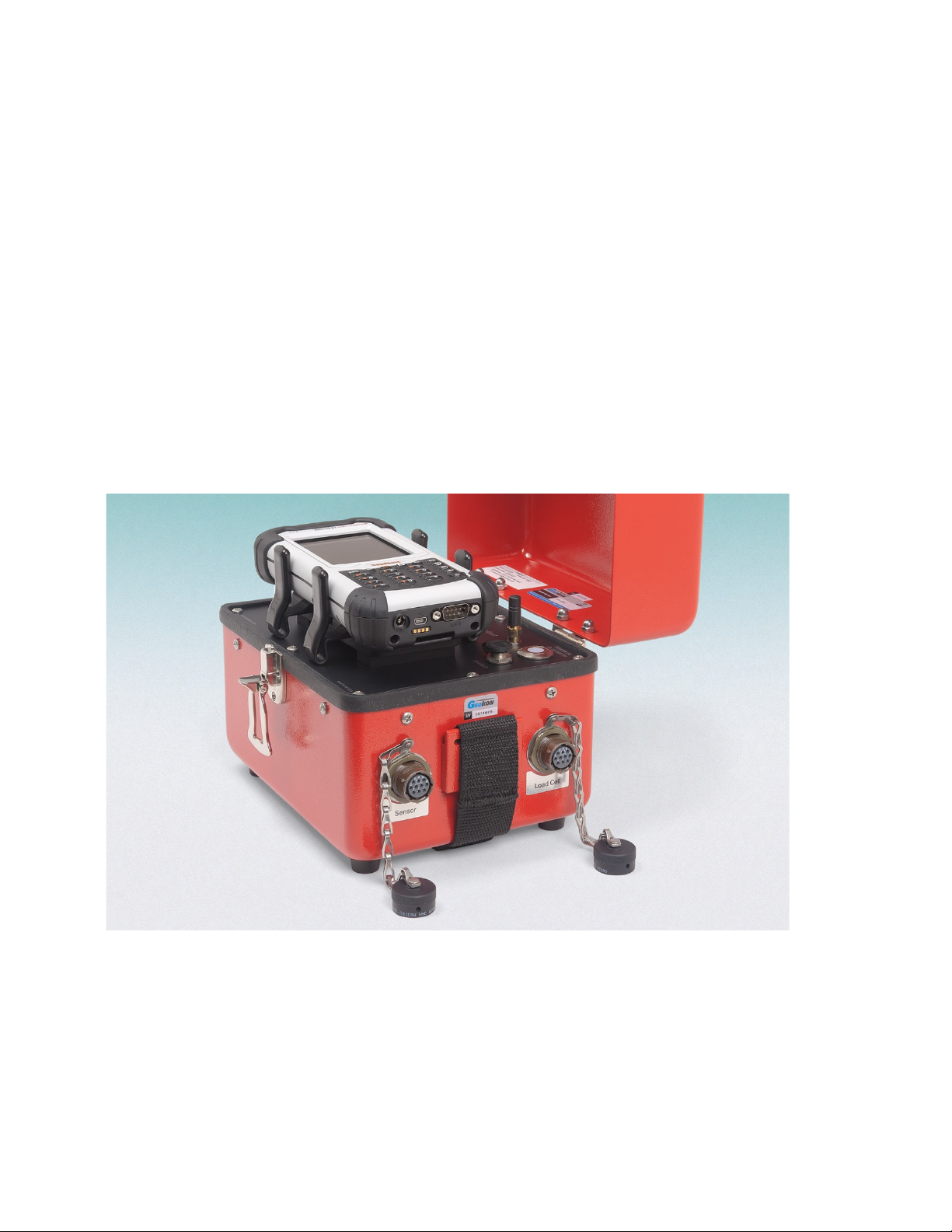
FIGURE 2-VIBRATING WIRE GAGE AND LOAD CELL CONNECTORS (SHOWN WITH THE FPC-1)....................................2
FIGURE 3-HANDHELD PC (FPC-2) RUNNING GK-405 VWRA .....................................................................................3
FIGURE 4-LIVE READINGS –RAW READINGS ...............................................................................................................5
FIGURE 5-SELECT WORKSPACE NAME .........................................................................................................................5
FIGURE 6-STARTING BLUETOOTH MANAGER ...............................................................................................................6
FIGURE 7-TURN ON BLUETOOTH ..................................................................................................................................6
FIGURE 8-ADD NEW DEVICE ........................................................................................................................................7
FIGURE 9-SELECT A BLUETOOTH DEVICE.....................................................................................................................7
FIGURE 10 -ENTER PASSCODE .......................................................................................................................................8
FIGURE 11 -NEW OUTGOING PORT................................................................................................................................8
FIGURE 12 -ADD A DEVICE............................................................................................................................................9
FIGURE 13 -COM PORT SELECTION ..............................................................................................................................9
FIGURE 14 -SERIAL PORT CHECK BOX ........................................................................................................................10
FIGURE 15 -CONNECT BUTTON....................................................................................................................................10
FIGURE 16 -ACTIVESYNC WINDOW SHOWING ACTIVE CONNECTION...........................................................................11
FIGURE 17 -WINDOWS MOBILE DEVICE CENTER ........................................................................................................12
FIGURE 18 -WINDOWS EXPLORER WINDOW DISPLAYING HHD ROOT FOLDER.............................................................13
FIGURE 19 -HANDHELD DEVICE ROOT FOLDER CONTENTS...........................................................................................13
FIGURE 20 -INSTALLATION FOLDER CONTENTS ..........................................................................................................14
FIGURE 21 -GK-405 INSTALLER AT ROOT OF HDD.....................................................................................................14
FIGURE 22 -GK-405 INSTALL SCREEN.........................................................................................................................15
FIGURE 23 -GK-405 VWRA ICON IN START->PROGRAMS..........................................................................................15
FIGURE 24 -SELECT WORKSPACE NAME .....................................................................................................................16
FIGURE 25 -WORKSPACE FOLDER SELECTION.............................................................................................................17
FIGURE 26 -WORKSPACE EXIST...................................................................................................................................17
FIGURE 27 -REMOTE MODULE NOT FOUND ..................................................................................................................18
FIGURE 28 -DEFAULT INITIAL SCREEN.........................................................................................................................18
FIGURE 29 -LIVE READINGS –RAW READINGS ...........................................................................................................19
FIGURE 30 -DISPLAY MODE DROPDOWN MENU..........................................................................................................20
FIGURE 31 -SENSOR INDEX DROPDOWN CONTROL......................................................................................................21
FIGURE 32 -MENU OPTIONS ........................................................................................................................................21
FIGURE 33 -VIEW OPTIONS..........................................................................................................................................21
FIGURE 34 -SENSOR SELECTION SCREEN.....................................................................................................................22
FIGURE 35 -PROJECT EXPLORER WITH EXPANDED PROJECTS.......................................................................................23
FIGURE 36 -CONTEXT MENU.......................................................................................................................................24
FIGURE 37 -WORKSPACE SELECTION WINDOW...........................................................................................................24
FIGURE 38 -LIST OF WORKSPACE NAMES....................................................................................................................24
FIGURE 39 -WORKSPACE FOLDER SELECTION.............................................................................................................25
FIGURE 40 -SORT ELEMENTS SUB-ITEMS ....................................................................................................................26
FIGURE 41 -APPLICATION MENU.................................................................................................................................26
FIGURE 42 -SENSOR SELECTION SCREEN,REMOTE MODULE CONNECTED..................................................................27
FIGURE 43 -LIVE READINGS MENU SELECTIONS.........................................................................................................27
FIGURE 44 -LIVE READINGS SCREEN (SENSOR SELECTED)..........................................................................................28
FIGURE 45 -MENU OPTIONS ........................................................................................................................................29
FIGURE 46 -CLEAR DATA WARNING ...........................................................................................................................29
FIGURE 47 -STORAGE CONFIGURATION DIALOG .........................................................................................................30
FIGURE 48 -VIEW OPTIONS..........................................................................................................................................31
FIGURE 49 -DISPLAYED SENSOR READINGS ................................................................................................................31
FIGURE 50 -LIVE READINGS -WITH SELECTED SENSOR (LANDSCAPE MODE) ............................................................32
FIGURE 51 -REMOTE MODULE NOT FOUND.................................................................................................................32
FIGURE 52 -DEFAULT INITIAL SCREEN........................................................................................................................32
FIGURE 53 -REMOTE CONNECT WITH... .......................................................................................................................33
FIGURE 54 -SELECT COM PORT..................................................................................................................................33

FIGURE 55 -SENSOR SELECTION SCREEN,REMOTE MODULE CONNECTED..................................................................33
FIGURE 56 -TERMINAL WINDOW .................................................................................................................................34
FIGURE 57 -FILE MENU OPTIONS.................................................................................................................................35
FIGURE 58 -DELETE DATA FILES WINDOW..................................................................................................................35
FIGURE 59 -EXPORT MENU..........................................................................................................................................36
FIGURE 60 -EXPORT DATA WINDOW...........................................................................................................................36
FIGURE 61 -SAVE FILE WINDOW .................................................................................................................................37
FIGURE 62 -EXTENDED FORMAT WINDOW ..................................................................................................................37
FIGURE 63 -SELECT SENSOR(S)TO EXPORT.................................................................................................................38
FIGURE 64 -SELECT EXPORT FOLDER AND MODE........................................................................................................39
FIGURE 65 -EXPORT PATH SELECTION WINDOW .........................................................................................................40
FIGURE 66 -NO PROJECT SELECTED ERROR.................................................................................................................40
FIGURE 67 -SELECT PROJECT EXPORT FILE .................................................................................................................41
FIGURE 68 -DATA FILE SELECTION WINDOW ..............................................................................................................41
FIGURE 69 -SENSOR READS WINDOW..........................................................................................................................42
FIGURE 70 -PROJECT SETTINGS ...................................................................................................................................43
FIGURE 71 -SENSOR SETTINGS WINDOW (PAGE ONE).................................................................................................44
FIGURE 72 -SENSOR SETTINGS (49XX SELECTED)........................................................................................................45
FIGURE 73 -CONVERSION METHOD RADIO BUTTONS ..................................................................................................45
FIGURE 74 -LINEAR COEFFICIENTS..............................................................................................................................46
FIGURE 75 -POLYNOMIAL COEFFICIENTS.....................................................................................................................47
FIGURE 76 -UNITS CONVERSION..................................................................................................................................48
FIGURE 77 -SENSOR SETTINGS (PAGE 4, NAUTIZ X8 SHOWN)......................................................................................49
FIGURE 78 -NONSTANDARD THERMISTOR COEFFICIENTS............................................................................................50
FIGURE 79 -CANNOT CONNECT ERROR MESSAGE (NAUTIZ X8 SHOWN) .....................................................................53
FIGURE 80 -BLUETOOTH DEVICE CONTEXT MENU......................................................................................................54
FIGURE 81 -CONNECTION PROBLEM ERROR (NAUTIZ X8 SHOWN) ..............................................................................55
FIGURE 82 -BLUETOOTH SETTINGS WINDOW,COM PORTS TAB.................................................................................56
FIGURE 83 -REMOTE CONNECT WITH...........................................................................................................................56
FIGURE 84 -SINGLE SENSOR CONNECTOR....................................................................................................................58
FIGURE 85 -LOAD CELL CONNECTOR ..........................................................................................................................59
FIGURE 86 -CHARGER CONNECTION............................................................................................................................61
FIGURE 87 -REMOVING THE FACE PLATE ....................................................................................................................62
FIGURE 88 -FUSE LOCATION........................................................................................................................................63
FIGURE 89 -ENHANCED DATA TEXT REPORT ..............................................................................................................67
TABLES
TABLE 1-DISPLAY MODE OPTIONS (A-F)....................................................................................................................20
TABLE 2-SENSOR SELECTION COMPONENTS...............................................................................................................22
TABLE 3-FOLDER PATHS AND FILE NAMES.................................................................................................................51
TABLE 4-SINGLE SENSOR PIN-OUT .............................................................................................................................58
TABLE 5-LOAD CELL CONNECTOR PIN-OUT ...............................................................................................................59
TABLE 6-LOAD CELL CONNECTOR AND CABLE (STANDARD WIRING) .......................................................................60
TABLE 7-REMOTE MODULE COMMAND FORMAT .......................................................................................................64

1
1. INTRODUCTION
The GK-405 Vibrating Wire Readout is made up of two components:
•The Readout Unit, consisting of a Windows Mobile handheld PC running the GK-405
Vibrating Wire Readout Application
•The GK-405 Remote Module is housed in a weatherproof enclosure and connects to the
vibrating wire gage to be measured.
Figure 1 - GK-405 with Handheld PC in Cradle (Shown with the FPC-2)
The two components communicate wirelessly using Bluetooth®, a reliable digital
communications protocol. The Readout Unit can operate from the cradle of the Remote Module
(as shown in Figure 1) or, if more convenient, can be removed and operated up to 20 meters from
the Remote Module. (Note: In most cases 20 meters will be the maximum but differences in
battery, atmospheric and geographic conditions may reduce the actual effective range.)

2
1.1 Features
Rugged, general purpose, reliable readout based on a Windows Mobile handheld PC:
•All the benefits of a Windows compatible device (Windows file system, RS-232, USB and
wireless connectivity)
•Long battery life
•Ease of use
Lightweight and simple Remote Module:
•Lithium battery (8+ hours of continuous use)
•One button operation; automatic power down when Bluetooth connection is dropped or after
several minutes of inactivity
•Reliable connection to standard vibrating wire gages and load cells is accomplished via two
10-pin bulkhead connectors (see Figure 2)
•Housed in a durable aluminum enclosure
Figure 2 - Vibrating Wire Gage and Load Cell Connectors (Shown with the FPC-1)

3
1.2 GK-405 Accessories
The GK-405 is sold with the following accessories:
•GK-403-2 flying leads
•CHG-04 universal charger
•Universal power adapter
•Three replacement fuses
1.3 GK-405 Vibrating Wire Readout Application
The GK-405 Vibrating Wire Readout Application (GK-405 VWRA) installs and runs on a
ruggedized handheld PC (see Figure 3) and is designed to communicate via Bluetooth with
Remote Modules connected to vibrating wire gages.
Figure 3 - Handheld PC (FPC-2) Running GK-405 VWRA
1.4 Before using the GK-405 Vibrating Wire Readout
The readout software runs as an application under Windows Mobile 5 or 6 operating system
installed on a handheld PC.
•Please familiarize yourself with the handheld PC and the Windows Mobile OS.
•It is assumed in the instructions below that you can launch applications from the Start button
including File Explorer and the Bluetooth Settings manager.
•It is assumed that you can tap the keyboard icon as needed and use the onscreen keyboard to
enter text and numbers.

4
2. INSTALLATION AND OPERATION
NOTE: For those users that have purchased a complete GK-405 system the Field PC has been
pre-programmed to operate with the GK-405. This includes the Bluetooth pairing between the
Field PC and the GK-405.
The steps described in Sections 2.1 and 2.2 are an attempt to guide the user through the process
of launching the GK-405 VWRA, connecting to the sensor, and taking a reading. If all parts of
the GK-405 are purchased as a system, Geokon makes every effort to ensure that the system is
completely set up and working before it leaves the factory. Other times, the user may already
own the handheld PC and are setting up their hardware and software for the very first time. The
steps below attempt to cover all cases and refer the user to the appropriate section when more
information is needed.
For those users that have purchased a complete GK-405 system, a workspace with the name of
“GK405” will have been predefined and the handheld unit will already be paired with the
Remote Module. Note that the workspace name can be changed at any time (see Section 4) or
new ones can be created (see Section 3.4). When purchasing a GK-405 system, Sections 2.2
through 2.4 can possibly be skipped but a quick review is recommended.
2.1 Connecting Sensors
2.1.1 Sensors with 10-pin Connectors Attached
Align the grooves on the sensor connector (male), with the appropriate connector on the
readout (female connector labeled senor or load cell). Push the connector into place, and
then twist the outer ring of the male connector until it locks into place. For more
information on the sensor connectors of the remote module, refer to Appendix A.
2.1.2 Sensors with Bare Leads
Attach the GK-403-2 flying leads to the GK-405 by aligning the grooves on connector of
the flying leads (male), with the connector on the unit (female). Push the connector into
place and then twist the outer ring of the male connector until it locks into place. Attach
the bare leads of a Geokon vibrating wire sensor by connecting each of the clips on the
leads to the matching colors of the sensor conductors, with blue representing the shield
(bare).
2.2 Initial Quick Start Sequence
The following steps are a guide to the typical operation of the GK-405 and, if followed, should
result in a successful sensor measurement:
1) If the Remote Module has been previously paired with the handheld unit, then press the
button labeled “POWER ON (BLUETOOTH)”. A blue light should turn on and begin
blinking, signifying that the Remote Module is waiting to connect to the handheld unit.

5
If the Remote Module was purchased separately from the handheld unit, see Section 2.3,
“Establishing Contact with the Remote Module”.
Launch the GK-405 VWRA by tapping on “Start” from the handheld PC’s
main window, then tap “Programs”, and then tap the GK-405 VWRA icon
(shown to the right).
If the GK-405 Vibrating Wire Readout Application has not been installed, please see Section
2.4, “Installing the GK-405 VWRA”.
2) After a few seconds, the blue light on the Remote Module should change to a steady state
blue (lit but not flashing) and the Live Readings Window will be displayed (Figure 4). If the
window shown in Figure 5 is displayed instead of the Live Readings Window, please refer to
Section 2.5, “Starting the Vibrating Wire Readout the first time”. If the Live Readings
Window is displayed but no Thermistor or Vibrating Wire output is shown, please refer to
Appendix A, “GK-405 Connections”.
Figure 5 - Select Workspace Name
3) From the Live Readings Window, different display modes may be selected as appropriate for
the sensor (see Section 3.2.1, “Display Mode”). If a sensor is connected that contains more
than one vibrating wire “cell”, the “Sensor Index” may be changed to view the vibrating wire
output for each “cell”, or the average may be displayed.
4) If displaying sensor output in engineering units is desired, tap on “View” then “Sensor
Selection Screen” to select a predefined sensor or to create a new sensor configuration.
Please refer to Section 3.3, “Sensor Selection Screen” as well as, Section 4.2, “Sensor
Configuration”.
5) To close the GK-405 VWRA from the Live Readings Screen, tap “Menu” then “Close GK-
405”.
Figure 4 - Live Readings – Raw Readings

6
2.3 Establishing Contact with the Remote Module
In general, this should only need to be done once and is typically done before it leaves the
factory. Follow the steps below to ensure the ‘partnership’ with the remote is established before
using the readout software:
1) Use the Bluetooth Settings Manager on the handheld PC to set up the link to the remote.
Read about setting up a Bluetooth “partnership” in Chapter 9 of the handheld PC’s Reference
Guide. See Figure 6 below for two examples of how to start Bluetooth Manager.
Figure 6 - Starting Bluetooth Manager
2) Once in the Bluetooth Settings Manager, click on the “Mode” tab and then make sure that the
box next to “Turn on Bluetooth” is checked (Figure 7).
Figure 7 - Turn on Bluetooth
Two ways to start the
Bluetooth Manager

7
3) Click on the “Devices” tab, if it shows a “Geokon” device (name will start with “GK405”
and contain the remote’s serial number), go to step six. Otherwise, turn on the remote module
(should see a flashing blue indicator on the remote) and select “Add new device…”.
Figure 8 - Add New Device
4) When a suitable remote is discovered, highlight the device and tap “Next”.
Figure 9 - Select a Bluetooth Device

8
5) A prompt will be displayed for a password; enter “default” and tap “Next” again. If a
partnership with the device is successfully established, the screen will momentarily display
the prompt shown at the bottom of Figure 10 and then return to the Bluetooth Devices screen.
Figure 10 - Enter Passcode
6) Click on the COM Ports tab, if the “Geokon” device is already assigned to a COM Port skip
to step nine. If no COM Port is assigned, tap on “New Outgoing Port”. In the example shown
in Figure 11, there is no COM Port assigned to a “GK405” device.
Figure 11 - New Outgoing Port

9
7) The screen shown in Figure 12 will be displayed. Select the appropriate device from the list
and tap “Next”.
Figure 12 - Add a Device
8) From the “Port:” dropdown list, select a COM port (COM5 is the default). Be sure to
remember the number of the COM port as you may have to select it later in the readout
software (see Section 3.5.3). Make sure to “uncheck” the “Secure Connection” checkbox
(Figure 13). Tap “Finish” when done to return to the Bluetooth Settings “COM Ports” screen.
Note: If using a Nautiz X7, COM5 may be available, depending on the model.
Figure 13 - COM Port Selection

10
9) Lastly verify that the Bluetooth device is set for Serial Port operation. From the “Devices”
tab of the Bluetooth Settings manager, tap the device to be used to communicate with the
remote. Figure 14 will be displayed. Ensure that the “Serial Port” checkbox is checked. Tap
“Save” to complete the Bluetooth Settings.
Figure 14 - Serial Port Check Box
NOTE: After “Save” is selected, you will be brought back to the “Devices” window. There will
be a “Connect” button available at the bottom of the screen. See Figure 15 below.
DO NOT USE THE “CONNECT” BUTTON TO TEST THE CONNECTION!
It will always fail after the pairing has been made successfully. Test the pairing by entering the
GK-405 VWRA application.
Figure 15 - Connect Button

11
2.4 Installing the GK-405 VWRA
The installation of the GK-405 VWRA requires the following:
•A Handheld device (HHD) running Windows Mobile Classic 5.X (6.X recommended) or
higher with at least 50 Mbytes of free memory.
•HHD must be Bluetooth enabled and able to assign a Bluetooth connection to a COM
port.
•Windows .NET 3.5 Compact Framework (CF) and .NET framework English Language
Messages Package installed on HHD.
•Both “CAB” file installers are included in the GK-405 VWRA installer “Zip” file,
available on Geokon’s website (http://www.geokon.com/GK-405).
•Microsoft ActiveSync version 4.5.0 or higher installed on the host PC if host PC
operating on Windows XP (see Figure 16). If host PC’s operating system is Vista,
Windows 7 or Windows 8 then Windows Mobile Device Center should be installed on
the host PC (Figure 17 on the following page). An active connection between the host PC
and the HHD must be established either via a physical link or Bluetooth.
Note: For customers using a PC running Window 10 operating system; Windows Mobile Device
Center (WMDC) may no longer operate as it should because of an operating system update
(released October of 2017) called “Fall Creator Update”. If WMDC no longer launches when a
mobile device is connected via USB cable or will not manually launch, the link below should
help fix the issue. Please note that administrative privileges are need to launch some of the files
involved in the fix so your local IT person may need to be involved. The fix can be accessed via
the following link:
https://www.handheldgroup.com/support-rugged-computers/knowledgebase-KB/22996/
Should the link above fail to fix the WMDC launch problem, the link below offers another
possible solution:
http://www.junipersys.com/Juniper-Systems-Rugged-Handheld-Computers/support/Knowledge-
Base/Support-Knowledge-Base-Topics/Desktop-Connection-ActiveSync-or-Windows-Mobile-
Device-Center/WMDC-in-Windows-10
Figure 16 - ActiveSync Window Showing Active Connection

12
Figure 17 - Windows Mobile Device Center
Other manuals for GK-405
2
Table of contents
Other Geokon Measuring Instrument manuals

Geokon
Geokon 4200ER User manual

Geokon
Geokon 6300 User manual

Geokon
Geokon 4410 User manual

Geokon
Geokon 4425 User manual

Geokon
Geokon 4580 User manual

Geokon
Geokon GK-404 User manual

Geokon
Geokon 4500MLP User manual

Geokon
Geokon GK-604D User manual

Geokon
Geokon 6165 User manual

Geokon
Geokon 4675LV User manual

Geokon
Geokon GK-604D User manual

Geokon
Geokon 4420 User manual

Geokon
Geokon 6150F User manual

Geokon
Geokon 6350 User manual

Geokon
Geokon GK-604D User manual

Geokon
Geokon GK-604D User manual

Geokon
Geokon 4700 User manual

Geokon
Geokon 1100 User manual

Geokon
Geokon 4370 User manual

Geokon
Geokon 3900 User manual