GESTRA NRS 1-55 User manual

1
EN
English
Level Switch
NRS 1-54
NRS 1-55
Original Installation Instructions
819178-01

2
Contents
Usage for the intended purpose ..............................................................................................................4
Function .................................................................................................................................................4
Safety note .............................................................................................................................................5
Important notes
Page
Directives and standards
VdTÜV Bulletin “Wasserstand 100” (= Water Level 100)..........................................................................6
LV (Low Voltage) Directive and EMC (Electromagnetic Compatibility) .......................................................6
ATEX (Atmosphère Explosible).................................................................................................................6
Note on the Declaration of Conformity / Declaration by the Manufacturer .........................................6
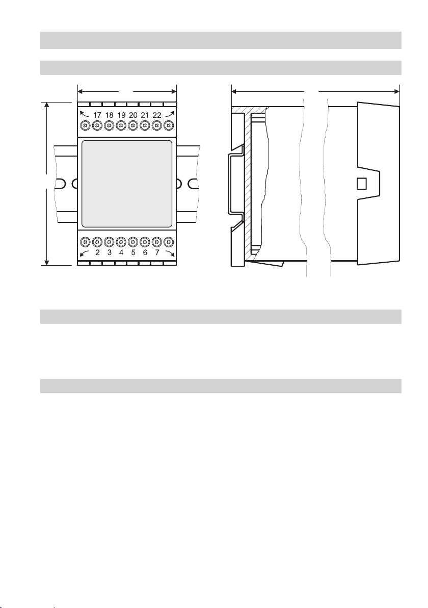
Dimensions NRS 1-54, NRS 1-55............................................................................................................9
Key.........................................................................................................................................................9
Installation in control cabinet ..................................................................................................................9
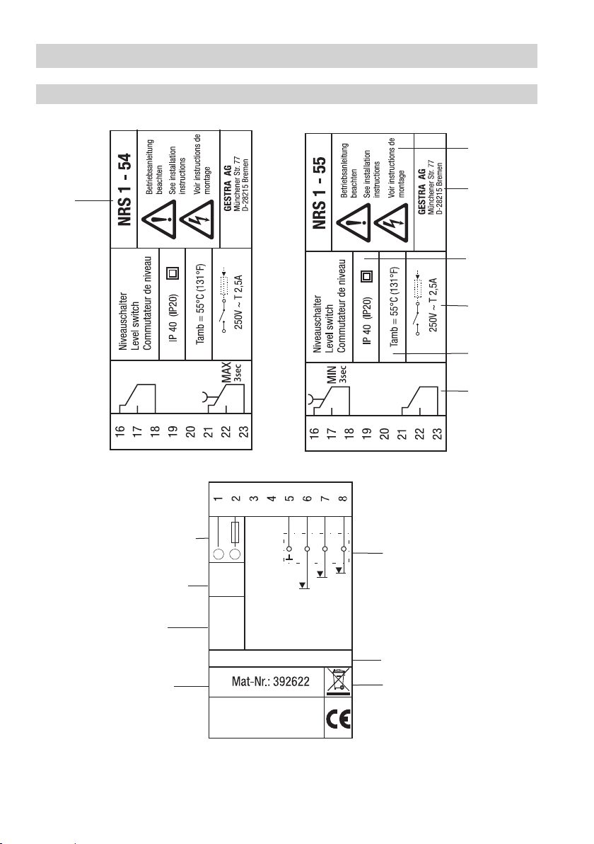
Name plate / marking ...........................................................................................................................10
In control cabinet: Mounting level switch
Wiring diagram for level switch NRS 1-54, NRS 1-55............................................................................11
Key.......................................................................................................................................................11
Connecting supply voltage ....................................................................................................................12
Connecting output contacts .................................................................................................................12
Connecting level electrode....................................................................................................................12
Tools.....................................................................................................................................................12
In control cabinet: Wiring level switch
Level switch NRS 1-54: Connecting several level electrodes (fill control)...............................................13
Key.......................................................................................................................................................13
Level switch NRS 1-55: Connecting several level electrodes (fill control)...............................................14
Key.......................................................................................................................................................14
Connecting level electrode....................................................................................................................15
In the plant: Wiring level electrode
NRS 1-54, NRS 1-55.........................................................................................................................7 – 8
Scope of supply......................................................................................................................................8
Technical data

3
Contents - continued -
Page
Changing response sensitivity and function ..........................................................................................16
Changing response sensitivity...............................................................................................................16
Changing function.................................................................................................................................17
Level switch NRS 1-54: Checking switchpoint and function .......................................................... 18 - 19
Level switch NRS 1-55: Checking switchpoint and function .......................................................... 20 - 21
Commissioning procedure
Level switch NRS 1-54: Indications and operation.................................................................................22
Level switch NRS 1-55: Indications and operation.................................................................................23
Operation, alarm and test
Basic settings
Factory setting......................................................................................................................................15
Protection against high frequency interference .....................................................................................24
Decommissioning / replacing the equipment ........................................................................................24
Disposal................................................................................................................................................24
Further notes

4
Important Notes
Usage for the intended purpose
The level switch NRS 1-54, NRS 1-55 in conjunction with level electrodes NRG 1.-.. and ER 5. is used
as water level controller, for instance in steam boilers, (pressurized) hot-water installations as well as
condensate and feedwater tanks. The level switch detects and indicates in addition a MIN or a MAX
water level.
The level switch NRS 1-54, NRS 1-55 can be used in combination with the following level electrodes:
Level electrodes
NRG 10-52,
NRG 16-52
Electrode with
4 rods
NRG 16-36
Electrode with 4
rods
NRG 16-4
Electrode with
1 rod
ER 50
Electrode with
4 rods
ER 56
Electrode with
4 rods
The operation of the level switch NRS 1-54, NRS 1-55 is based on the conductive measuring principle
using the electrical conductivity of water. The level switch is designed for different electrical conduc-
tivities and for connecting three level electrode rods.
The level switch works as on-off water level controller (for fill or discharge control) and indicates in
addition when the preset MAX or MIN water level (MAX: NRS 1-54; MIN: NRS 1-55) is reached.
The length of the associated electrode rods determines the switchpoints for water level control and
MIN or MAX water level.
The equipment monitors the water level by sensing whether the electrode tips are exposed or im-
mersed and - by energizing or de-energizing the controller output contact - switches the feedwater
pump on or off. The LED “Pump” is illuminated when the feedwater pump is switched on by the level
switch.
The level switch detects that the MIN or MAX water level is reached when the corresponding electrode
rod is exposed or submerged. After the de-energizing delay has elapsed, the MIN / MAX output contact
is switched over. At the same time the MIN or the MAX LED changes from green to red.
A MIN or MAX alarm can be simulated by pressing the button “Test”.
Function

5
Safety note
The equipment fulfils a safety function and must only be installed, wired and commissioned by quali-
fied and competent staff.
Retrofitting and maintenance work must only be performed by qualified staff who - through adequate
training - have achieved a recognised level of competence.
Danger
The terminal strips of the equipment are live during operation.
This presents the danger of electric shock!
Always cut off power supply to the equipment before mounting, removing or connect-
ing the terminal strips!
Attention
The name plate specifies the technical features of the equipment. Note that any piece of
equipment without its specific name plate must neither be commissioned nor operated.
Important Notes - continued -

6
Directives and Standards
VdTÜV Bulletin “Wasserstand 100” (= Water Level 100)
The level switch NRS 1-54, NRS 1-55 in conjunction with level electrodes NRG 10-52, NRG 16-52;
NRG 16-36, NRG 16-4 and ER 5.-1 is type approved to VdTÜV Bulletin “Water Level 100”.
The VdTÜV Bulletin “Wasserstand (= Water Level) 100” specifies the requirements made on water level
control and limiting equipment for boilers.
ATEX (Atmosphère Explosible)
According to the European Directive 20014/34/EU the equipment must not be used in explosion risk areas.
Note
The level electrodes NRG 10-52, NRG 16-52, NRG 16-36, NRG 16-4 and ER 5.-1 are
simple items of electrical equipment as specified in EN 60079-11 section 5.7.
According to the European Directive 2014/34/EU the equipment must be equipped with
approved Zener barriers if used in potentially explosive areas.
Applicable in Ex zones 1, 2 (1999/92/EC).
The equipment does not bear an Ex marking.
LV (Low Voltage) Directive and EMC (Electromagnetic Compatibility)
The equipment meets the requirements of the Low Voltage Directive 2014/35/EU and the EMC Directive
2014/30/EU.
Note on the Declaration of Conformity / Declaration by the Manufacturer
For details on the conformity of our equipment according to the European Directives see our Declara-
tion of Conformity or our Declaration of Manufacturer.
The current Declaration of Conformity / Declaration of Manufacturer are available in the Internet under
www.gestra.com/documents or can be requested from us.

7
NRS 1-54, NRS 1-55
Supply voltage
24 VDC +/– 20 %
Fuse
external 0.5 A (semi-delay)
Power consumption
2 VA
Connection of level electrode
3 inputs for level electrode NRG 10-52, NRG 16-52, NRG 16-36, NRG 16-4 and ER 5.-1,
4 poles with screen
Electrode voltage
5 VSS
Response sensitivity (Electrical conductivity of water at 25 °C)
> 0.5 ... < 1000 μS/cm or > 10 ... < 10 000 μS/cm (switch-selectable)
Outputs
2 volt-free change-over contacts, 8 A 250 V AC / 30 V DC cos ϕ= 1.
De-energizing delay: 3 sec. (MIN or MAX alarm).
Provide inductive loads with RC combinations according to manufacturer’s specification to ensure
interference suppression.
Indicators and adjustors
1 Test button for MIN / MAX alarm,
1 red/green LED for indicating operating mode and MIN / MAX alarm,
1 red/green LED for indicating operating mode and Pump ON
1 green LED for "Power ON",
1 code switch with 4 poles for changing the sensitivity and function
Housing
Housing material: base: polycarbonate, black; front: polycarbonate, grey
Conductor size: 1 x 4.0 mm² solid per wire or
1 x 2.5 mm2per stranded wire with sleeve to DIN 46228 or
2 x 1.4 mm2per stranded wire with sleeve to DIN 46228;
Terminal strips can be detached
Fixing of housing: Mounting clip on supporting rail TH 35, EN 60715
Electrical safety
Pollution degree 2 for installation in control cabinet with protection IP 54, completely insulated
Protection
Housing: IP 40 to EN 60529
Terminal strip: IP 20 to EN 60529
Weight
approx. 0.2 kg
Technical Data

8
NRS 1-54, NRS 1-55 - continued -
Ambient temperature
when system is switched on: 0 .... 55 °C, during operation: –10 ... 55 °C
Transport temperature
–20 ... +80 °C (< 100 hours), defrosting time of the de-energized equipment before it can be put into
operation: 24 hours.
Storage temperature
–20 ... +70 °C, defrosting time of the de-energized equipment before it can be put into operation:
24 hours.
Relative humidity
max. 95 %, no moisture condensation
Approvals:
TÜV certificate VdTÜV Bulletin “Water Lever 100” (= Water Level 100):
Requirements made on water level limiting & control equipment.
Type approval no. TÜV . WR/WB . XX-424 (see name plate)
Technical Data - continued -
Scope of supply
NRS 1-54
1 Level switch NRS 1-54
1 Installation manual
NRS 1-55
1 Level switch NRS 1-55
1 Installation manual

9
In control cabinet: Mounting level switch
Dimensions NRS 1-5..
Fig. 1
1Upper terminal strip
2Lower terminal strip
Key
Installation in control cabinet
The level switch NRS 1-54, NRS 1-55 is clipped onto the support rail 4type TH 35,
EN 60715 in the control cabinet. Fig. 1
3Housing
4Supporting rail type TH 35, EN 60715
2
74
1
4 3
46 120

10
M 0,5A
24 V =
+/- 20%
NRG 1.-..
ER 5.
2 VA
TÜV.WR/WB.xx-424
+
_
A
B
C
D
43 21
Folge - Typenschild
NRS 1-54
CorelDraw X3
Examiner
Designer
Drawer
Scale
Refer to protection
notice ISO 16016!
Free size tolerance
ISO 2768 mk 1:1
No Änderung/Modification Datum/Date Geänd/Modif. PrüferKonstr.
Datum/Date Name/Name
Nr./No
Ersatz für/Replaces Ersetzt durch/Replaced by
Ersteller/
Konstrukteur/
Prüfer/
Freimaßtoleranzen
ISO 2768 mk
GESTRA
Schutzvermerk
ISO 16016 beachten!
Maßstab/
Nr./ M-Nr.
--
Laupichler
2012-03-21
2012-03-21 Paul
4-392705-01
75
42
01 TÜV-Nr.: die TÜV.WR/WB. 10-424 in 15-424 geändert 50000152O.HadréPaul2016-03-23
In control cabinet: Mounting level switch - continued -
Name plate / marking
Name plate (on top)
Name plate (at the bottom)
Material number
Supply voltage
Fuse, provided on site
Power consumption
Disposal note
Approvals
Fig. 2
Connection of
level electrodes
Type
designation
Protection
Manufacturer
Ambient
temperature
External fuse
for output
contacts
Output
contacts
Serial number
Safety note

11
In control cabinet: Wiring level switch
Wiring diagram for level switch NRS 1-54, NRS 1-55
5
7
0
5Connection of supply voltage 24 V DC with fuse 0.5 A (semi-delay) provided on site
6Reference electrode or vessel used as functional earth
7MIN electrode rod
8MAX electrode rod
9Electrode rods for water level controller
0Central earthing point (CEP) in control cabinet
aMAX output contact
bMIN output contact
cOutput contact for water level controller
Key
8
ac
M 0.5 A
(semi-
delay) 6
Fig. 3
NRS 1-54 NRS 1-55
(–) (+)
(–) (+)
M 0.5 A
(semi-
delay)
5
6
c
b
0
99

12
In control cabinet: Wiring level switch - continued -
Connecting supply voltage
The equipment is supplied with 24 V DC and fused with an external semi-delay fuse 0.5 A.
Please use a safety power supply unit with safe electrical isolation.
The power supply unit must be electrically isolated from dangerous contact voltages and must meet at
least the requirements on double or reinforced isolation according to one of the following standards:
DIN EN 50178, DIN EN 61010-1, DIN EN 60730-1 or DIN EN 60950.
Connection of level electrode
To connect the level electrode(s) use screened multi-core control cable with a min. conductor size
0.5 mm2, e. g. LiYCY 4 x 0.5 mm2 , max. length: 100 m.
Wire terminal strip in accordance with the wiring diagram. Fig. 3.
Connect the screen only once to the central earthing point (CEP) in the control cabinet.
Make sure that connecting cables leading to the level electrodes are segregated and run separately
from power cables.
Tools
nFor all functions: Screwdriver 0.8 x 4.0 or 0.8 x 4.5, completely insulated according to VDE 0680-1.
Connecting output contacts
Wire the upper terminal strip 1(terminals 16-18, 21-23) according to the desired switching functions.
Provide an external slow-blow fuse 2.5 A for the output contacts.
When switching off inductive loads, voltage spikes are produced that may impair the operation of con-
trol and measuring systems. Connected inductive loads must be provided with suppressors such as RC
combinations as specified by the manufacturer.
Attention
nDo not use unused terminals as support point terminals.

13
e
g
Fig. 4 Fig. 5
Fig. 6 Fig. 7
In the plant: Wiring level electrode
Level switch NRS 1-54: Connecting several level electrodes (fill control)
dLevel electrode NRG 10-52, NRG 16-52
Five pole connector
eLevel electrode NRG 16-36
fLevel electrode ER 5..,4 pole connector
Key
gLevel electrode ER 5..,6 pole connector
hLevel electrode NRG 16-4
iCentral earthing point (CEP) in control cabinet
d
h
MAX
Pump OFF
Pump ON
f
12345678
NRG16-4
NRG16-4
NRG16-4
3
3
3
Fig. 8
MAX
Pump OFF
Pump ON
MAX MAX
Pump OFF
Pump ON
Pump OFF
MAX
Pump OFF
Pump ON
Pump ON
ii
i i
i
NRG 1.-52
NRS 1-54
NRS 1-54
NRS 1-54
NRS 1-54
NRS 1-54

14
e
g
Fig. 9 Fig. 10
Fig. 11 Fig. 12
In the plant: Wiring level electrode - continued -
Level Switch NRS 1-55: Connecting several level electrodes (drain control)
Key
d
h
Pump ON
Pump OFF
MIN
f
12345678
NRG16-4
NRG16-4
NRG16-4
3
3
3
Fig. 13
Pump ON
Pump OFF
MIN
Pump ON
Pump OFF
MIN
Pump ON
Pump OFF
MIN
Pump ON
Pump OFF
MIN
dLevel electrode NRG 10-52, NRG 16-52
Five pole connector
eLevel electrode NRG 16-36
fLevel electrode ER 5..,4 pole connector
gLevel electrode ER 5..,6 pole connector
hLevel electrode NRG 16-4
iCentral earthing point (CEP) in control cabinet
i
NRG 1.-52
i
i
i
i
NRS 1-55 NRS 1-55
NRS 1-55NRS 1-55
NRS 1-55

15
In the plant: Wiring level electrode - continued -
Connection of level electrode
The level switch NRS 1-54, NRS 1-55 can be used in combination with the following level electrodes:
Level electrodes
NRG 10-52,
NRG 16-52
Electrode with
4 rods
NRG 16-36
Electrode with 4
rods
NRG 16-4
Electrode with
1 rod
ER 50
Electrode with
4 rods
ER 56
Electrode with
4 rods
To connect the level electrode(s) use screened multi-core control cable with a min. conductor size
0.5 mm2, e. g. LiYCY 4 x 0.5 mm2, max. length: 100 m.
Wire terminal strip in accordance with the examples Fig. 4 to 13.
Check the connection of the screen to the central earthing point (CEP) in the control cabinet.
Attention
nPlease observe the instructions given in the installation & operating manual for the
NRG 10-52, NRG 16-52, NRG 16-36, NRG 16-4 and ER 5.-1!
nMake sure that connecting cables leading to the level electrodes are segregated and
run separately from power cables.
Factory settings
Level Switch NRS 1-54
The level switch features the following factory set default values:
nResponse sensitivity: 10 μS/cm (at 25 °C)
nFunction “Fill control”
Level Switch NRS 1-55
The level switch features the following factory set default values:
nResponse sensitivity: 10 μS/cm (at 25 °C)
nFunction “Discharge control”

16
5678123 4
The terminal strips of the equipment are live during operation.
This presents the danger of electric shock!
Always cut off power supply to the equipment before mounting, removing or connecting
the terminal strips!
Danger
Changing response sensitivity and function
The response sensitivity and the function are determined by the code switch jsetting.
To change the code switch setting proceed as follows:
nCut off supply voltage.
nRemove lower terminal strip. Fig. 14
nInsert a screwdriver to the right and left between the terminal strip and the front frame.
nUnlock terminal strip on the left and right side. For this purpose move screwdriver in direction
of the arrow .
nRemove the terminal strip.
Commissioning procedure
Fig. 14
After the new code switch settings have been established as new defaults:
nRe-attach lower terminal strip.
nApply mains voltage, equipment is re-started.
If the electrical conductivity of water is < 10 μS/cm at 25°C set switch S4 of the code switch j to ON
(= sensitivity of response 0.5 μS/cm).
Changing response sensitivity
j

17
Code switch j
Level switch NRS 1-54 S 1 S 2 S 3
Fill control ON ON OFF
Discharge control ON OFF ON
Level switch NRS 1-55
Fill control OFF OFF ON
Discharge control OFF ON ON
grey = factory setting
Fig. 15
Toggle switch, white
The NRS 1-54 is configured at our works as fill controller and the NRS 1-55 as discharge controller.
To change the function set the switches S1 to S3 of code switch jto the positions indicated in table
Fig. 15.
Commissioning - continued -
Changing function
13
ON 24
13
ON 24
13
ON 24
13
ON 24
Toggle switch, white

18
Start
Activity Display Function
Switch on supply voltage. LED “Power” is illuminated.
MAX LED and pump LED are illuminated as a function of the water level
Checking switchpoint and function (fill control)
Lower water level until it
is below “Pump ON” level.
Electrode rod “Pump ON” is
exposed.
Pump LED illuminated green. Pump output contact 17/18 closed, 16/18 open.
Fill vessel until water level
“Pump OFF” is exceeded.
Electrode rod “Pump OFF” is
submerged.
Pump LED is not illuminated. Pump output contact 16/18 closed, 17/18 open.
Checking switchpoint and function (discharge control)
Fill vessel until water level
“Pump ON” is exceeded.
Electrode rod “Pump ON” is
submerged.
Pump LED illuminated green. Pump output contact 17/18 closed, 16/18 open.
Lower water level until it is
below “Pump OFF” level.
Electrode rod “Pump OFF” is
exposed.
Pump LED is not illuminated. Pump output contact 16/18 closed, 17/18 open.
Commissioning - continued -
Level switch NRS 1-54: Checking switchpoint and function
TEST button
MAX LED red/green
Fig. 16
Pump LED red/green
LED “Power”
To commission the equipment switch water level control system to manual operation.
Make sure that installation is in manual operation mode when you fill or discharge the
steam boiler or vessel.
Danger

19
Commissioning - continued -
Level switch NRS 1-54: Checking switchpoint and function - continued -
Possible installation faults
Status and indication Error Remedy
Water level below MAX
switchpoint, MAX LED
illuminated red.
Electrode rods are too long. Cut electrode rods to the length dictated by the
switchpoints.
If installed inside the boiler: Up-
per vent hole in protection tube
does not exist or is obstructed.
Check installation of level electrode. Make sure
that the level in the protection tube corresponds
to the actual water level.
Switchpoint MAX water level
reached, MAX LED illuminated
green.
Electrode rods are too short. Replace level electrode and cut electrode rods
to the length dictated by the switchpoints.
The earth connection to the
vessel is interrupted.
Clean seating surfaces and screw in level elec-
trode with metallic joint ring. Do not insulate
the electrode with hemp or PTFE tape!
Electrical conductivity of the
boiler water too low. Change response sensitivity to 0.5 μS/cm
Upper vent hole flooded.
Check installation of level electrode. Make sure
that the level in the protection tube corresponds
to the actual water level.
Water level between MAX
and pump ON / OFF. MAX LED
and pump LED are flashing
simultaneously.
Electrical connections of elec-
trode rods are mixed up.
Check and change the electrical connection of
the level electrode.
Checking switchpoint and function (MAX alarm)
Fill vessel until MAX level is
exceeded. MAX electrode rod
enters the water.
MAX LED flashes red. De-energizing delay is running.
MAX LED illuminated red Time delay has elapsed. MAX output contact
21/23 closed, 22/23 open.

20
Start
Activity Display Function
Switch on supply voltage. LED “Power” is illuminated.
MIN LED and pump LED are illuminated as a function of the water level
Checking switchpoint and function (fill control)
Lower water level until it
is below “Pump ON” level.
Electrode rod “Pump ON” is
exposed.
Pump LED illuminated green. Pump output contact 22/23 closed, 21/23 open.
Fill vessel until water level
“Pump OFF” is exceeded.
Electrode rod “Pump OFF” is
submerged.
Pump LED is not illuminated. Pump output contact 21/23 closed, 22/23 open.
Checking switchpoint and function (discharge control)
Fill vessel until water level
“Pump ON” is exceeded.
Electrode rod “Pump ON” is
submerged.
Pump LED illuminated green. Pump output contact 22/23 closed, 21/23 open.
Lower water level until it is
below “Pump OFF” level.
Electrode rod “Pump OFF” is
exposed.
Pump LED is not illuminated. Pump output contact 21/23 closed, 22/23 open.
Commissioning - continued -
Level switch NRS 1-55: Checking switchpoint and function
TEST button
Pump LED red/green
Fig. 17
MIN LED red/green
LED “Power”
To commission the equipment switch water level control system to manual operation.
Make sure that installation is in manual operation mode when you fill or discharge the
steam boiler or vessel.
Danger
This manual suits for next models
1
Table of contents
Other GESTRA Switch manuals

GESTRA
GESTRA TRS 5-8 User manual

GESTRA
GESTRA NRS 1-53 User manual

GESTRA
GESTRA NRS 1-8 User manual

GESTRA
GESTRA NRS 2-50 User manual

GESTRA
GESTRA TRS 5-50 User manual

GESTRA
GESTRA NRS 2-50 User manual

GESTRA
GESTRA LRS 1-50 User manual

GESTRA
GESTRA TRS 5-52 User manual

GESTRA
GESTRA NRS 1-51 User manual

GESTRA
GESTRA NRS 1-52 User manual

GESTRA
GESTRA NRS 2-1 Quick guide

GESTRA
GESTRA LRS 1-50 User manual

GESTRA
GESTRA LRS 1-7 Manual

GESTRA
GESTRA LRS 1-50 User manual

GESTRA
GESTRA NRS 1-50 Series User manual

GESTRA
GESTRA NRS 1-50 User manual

GESTRA
GESTRA NRS 1-56 User manual

GESTRA
GESTRA NRS 1-51 User manual

GESTRA
GESTRA URS 2 User manual

GESTRA
GESTRA NRS 1-2 User manual