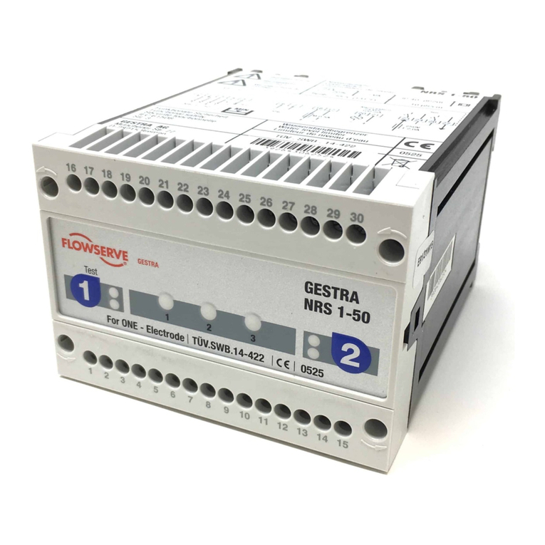
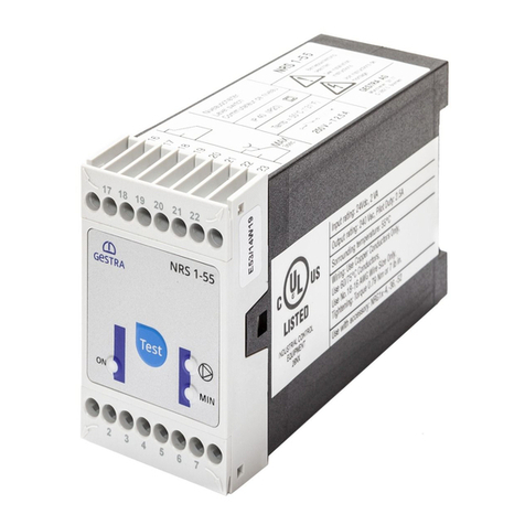
GESTRA NRS 1-50 User manual

Original Installation &
Operating Manual
850693-00
Level Switch
NRS 1-50
For ONE electrode
EN (USA)
English

2NRS 1-50 For ONE electrode - USA - Installation & Operating Manual - 850693-00
Contents
Content of this Manual......................................................................................................................... 4
Scope of supply, product package....................................................................................................... 4
How to use this Manual........................................................................................................................ 5
Illustrations and symbols used............................................................................................................ 5
Hazard symbols in this Manual............................................................................................................ 5
Types of warning .................................................................................................................................. 6
Specialist terms, abbreviations ........................................................................................................... 7
Usage for the intended purpose........................................................................................................... 8
Applicable directives and standards.............................................................................................. 8
Improper use ........................................................................................................................................ 8
Basic safety information ...................................................................................................................... 9
Required personnel qualifications..................................................................................................... 10
Notes on product liability................................................................................................................... 10
Function .............................................................................................................................................. 11
Technical data .................................................................................................................................... 12
Rating plate, identification................................................................................................................. 13
Factory default settings ..................................................................................................................... 14
Dimensions of the NRS 1-50 .............................................................................................................. 15
Important notes .................................................................................................................................. 16
Safety information ......................................................................................................................... 16
Preparing for installation ................................................................................................................... 17
Installation.......................................................................................................................................... 18
Electrical connection.......................................................................................................................... 19
Supply voltage............................................................................................................................... 19
Connecting the level electrode....................................................................................................... 19
Connecting the safety circuit.......................................................................................................... 19
Connecting the signal output ......................................................................................................... 20
Wiring diagram of level switch NRS 1-50....................................................................................... 21
Connection example for Class C..................................................................................................... 22
Example switching combinations ................................................................................................... 23
3NRS 1-50 For ONE electrode - USA - Installation & Operating Manual - 850693-00
Bringing into service .......................................................................................................................... 25
Checking the switchpoint and function........................................................................................... 25
Operation, alarm and test................................................................................................................... 26
Fault indications and troubleshooting............................................................................................... 27
Checking the level electrode.............................................................................................................. 28
Measuring level switch voltages .................................................................................................... 28
Important notes .................................................................................................................................. 29
Action against high-frequency interference.................................................................................... 29
Interlock and interlock deactivation................................................................................................ 29
Checking switchpoints................................................................................................................... 29
Taking out of service.......................................................................................................................... 30
Disposal .............................................................................................................................................. 30
UL components................................................................................................................................... 30

4NRS 1-50 For ONE electrode - USA - Installation & Operating Manual - 850693-00
Content of this Manual
Product:
■ Level Switch NRS 1-50, for ONE electrode
First edition:
BAN 850693-00/09-2021cm
© Copyright
All rights reserved. Any misuse, particularly reproduction and dissemination to third parties, is not
permitted. The General Terms & Conditions of GESTRA AG apply.
Scope of supply, product package
NRS 1-50
1 level switch NRS 1-50
1 Installation & Operating Manual

5NRS 1-50 For ONE electrode - USA - Installation & Operating Manual - 850693-00
How to use this Manual
This Installation & Operating Manual describes the correct use of the NRS 1-50 level switch. It
applies to persons who integrate this equipment in control systems, install, bring into service,
operate, maintain and dispose of this equipment. Anyone carrying out the above-mentioned
activities must have read this Installation & Operating Manual and understood its contents.
■ Read this Manual in full and follow all instructions.
■ Please also read the instructions for use of any accessories.
■ The Installation & Operating Manual is part of the product package. Keep it in an easily acces-
sible location.
Availability of this Installation & Operating Manual
■ Make sure this Installation & Operating Manual is always available to the operator.
■ If you pass on or sell the equipment to a third party, please also hand over the Installation &
Operating Manual.
Hazard symbols in this Manual
Danger zone, dangerous situation
Illustrations and symbols used
1. Action to be taken
2.
■ Lists
◆ Bullet points in lists
A Keys to illustrations
Additional
information
Read the relevant
Installation & Operating Manual

6NRS 1-50 For ONE electrode - USA - Installation & Operating Manual - 850693-00
Types of warning
DANGER
Warning of a dangerous situation that results in death or serious injury.
WARNING
Warning of a dangerous situation that may possibly result in death or serious injury.
CAUTION
Warning of a situation that may result in minor or moderate injury.
ATTENTION
Warning of a situation that results in damage to property or the environment.

7NRS 1-50 For ONE electrode - USA - Installation & Operating Manual - 850693-00
Specialist terms, abbreviations
Here, we explain some abbreviations, specialist terms, etc., which are used in this Manual.
NRGT .. / NRR.. / NRS.. / URS .. / URB .. / SRL .. / etc.
Equipment and type designations of GESTRA AG.
SELV
Safety Extra Low Voltage
Operating point (of the plant)
The operating point describes the operating parameters within which a plant or boiler is operated
in its nominal range. In a steam boiler, for example, these parameters would be output, pressure,
and temperature.
The design data may be a lot more stringent, however.
A boiler that is operated at 145psi (10bar) and 356°F (180°C) may be designed to withstand a
pressure of 870psi (60bar) and a temperature of 527°F (275°C), for example, which is therefore
not necessarily its operating point.

8NRS 1-50 For ONE electrode - USA - Installation & Operating Manual - 850693-00
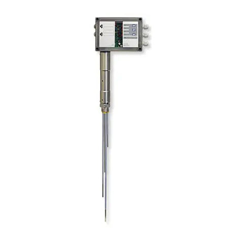
The NRS 1-50 level switch is used in conjunction with the NRG 1...-50 level electrode as a water
level limiter for steam boilers and hot water installations.
Water level limiters switch off the heating when the water drops below the set low water level (LW).
The NRS 1-50 is classified as a protective control Class B (C) in accordance with UL60730-1.
When used as intended, the NRS 1-50 level switch is combined in a circuit with the level elec-
trodes stipulated by the directives or standards below:
Level electrodes NRG 1...-..
UL60730-2-15
CAN/CSA E60730-2-15
NRG 16-50 NRG 17-50 NRG 19-50
Applicable directives and standards
The equipment has been tested and approved for use in the scope governed by the following
directives and standards:
Standards:
■UL 60730-1 and CAN/CSA E60730-1
General Requirements for Automatic Electrical Controls
■UL 60730-2-15 and CAN/CSA E60730-2-15
Requirements for Automatic Electrical Water Level Sensing Controls
Usage for the intended purpose
Improper use
There is a danger of death due to explosion if the equipment is used in potentially
explosive atmospheres.
Do not use the equipment in potentially explosive atmospheres.
Do not bring any equipment into service that does not have its own specific rating
plate.
The rating plate indicates the technical features of the equipment.

9NRS 1-50 For ONE electrode - USA - Installation & Operating Manual - 850693-00
There is a risk of electric shock during work on electrical systems.
■ Always switch off the voltage to the plant before performing connection work.
■ Check that the plant is not carrying live voltage before commencing work.
Attempts to repair the equipment will cause the plant to become unsafe.
■ The NRS 1-50 level switch may only be repaired by the manufacturer, GESTRA AG.
■ Only replace faulty equipment with identical equipment from GESTRA AG.
Basic safety information

10 NRS 1-50 For ONE electrode - USA - Installation & Operating Manual - 850693-00
Required personnel qualifications
Activity Personnel
Integration in control system Specialist staff Plant designer
Installation/
electrical connection/
bringing into service
Specialist staff
The equipment may only be installed, wired
and brought into service by qualified and
competent staff.
Operation Boiler service technician Staff trained by the plant operator.
Maintenance work Specialist staff
Fitting and maintenance work may only be
performed by authorized staff who have
undergone specific training.
Refits Specialist staff Persons trained by the plant operator to work
with pressure and temperature.
Notes on product liability
The manufacturer cannot accept any liability for damages resulting from improper use of the
equipment.

11NRS 1-50 For ONE electrode - USA - Installation & Operating Manual - 850693-00
The NRS 1-50 level switch is designed for different boiler water conductivities and for the
connection of a single level electrode.
If the water falls below the minimum level, the level electrode is exposed and an alarm is
triggered in the level switch. This switchpoint is determined by the length of the electrode
extension (level electrode NRG 1...-50).
When the off delay has elapsed, the two output contacts of the level switch open the safety circuit
for heating. The heating cut-off is interlocked in the external safety circuit and this interlock can
only be deactivated again when the level electrode is immersed once more. In addition, the signal
contact for external signaling devices closes without a delay. The NRS 1-50 level switch must be
used in combination with an external manual reset when used as a protective device per
ASME CSD-1.
An alarm is also triggered if faults occur in a level electrode and/or in the electrical connection.
If the level electrode is installed in a level pot outside the boiler, make sure the connection pipes
are sufficiently large.
The manufacturer recommends connection pipes of ≥ 1.57in (40mm) for steam and ≥ 3.94in
(100mm) for water. If smaller connection pipes or fittings are used, these shall not be smaller
than 1-inch NPS. The level pot must have a suitable flushing device at its lowest point. This device
flushes the connection pipes to the boiler and enables the function of the water level limiter to be
tested. No shut-off valves of any type shall be placed in the piping between the boiler and the low
water cut-off.
An automatic self-test monitors the safety functions in the level switch and the level electrode.
In the event of a fault, the safety circuit opens without a delay and switches the heating off.
Alarm and fault indications are displayed by LEDs and an alarm can be simulated by pressing a
button.
Function

12 NRS 1-50 For ONE electrode - USA - Installation & Operating Manual - 850693-00
Supply voltage
24 VDC +/– 20%, 0.3 A; SELV / PELV / CLASS2
100 – 240 VAC +10 / –15%, 47 – 63 Hz, 0.2 A (optional)
Fuse
External 0.5A; UL category JDYX, e.g., RND 170-00012
Power consumption
7 W
Response sensitivity [Water conductivity at 77°F (25°C)]
> 5 ... < 5000 ppm (> 10 ... < 10000 µS/cm)
Level electrode connection
1 input for NRG 1...-50 level electrode, 4-pole with shield.
Safety circuit
2 volt-free NO contacts, 6A 250 V AC / 30 V DC cos ϕ= 1.
Off delay 3 seconds.
Inductive loads must have interference suppression (RC combination) as specified by the manufacturer.
Signal output
2 volt-free outputs for external signaling without delay, 24 V DC, max. 100mA (semiconductor output).
Indicators and controls
2 buttons for testing and diagnosis,
2 red/green LEDs for indicating operating state and alarm.
3 red LEDs for diagnosis.
Terminal box
Terminal box material: base of black polycarbonate, front of gray polycarbonate
Wire size: 1 x AWG12 (4.0 mm2) solid, or
1 x AWG14 (2.5 mm2) stranded with sleeve acc. to DIN 46228, or
2 x AWG16 (1.4 mm2) stranded with sleeve acc. to DIN 46228
Terminal strips can be removed separately
Terminal box attachment: Mounting clip on support rail TH 35, EN 60715
Electrical safety
Pollution degree 2, overvoltage category II according to UL 60730-1
Protection
Terminal box: IP 40 according to EN 60529
Terminal strip: IP 20 according to EN 60529
As a UL open type, the equipment must be installed in a control cabinet.
Weight
Approx. 1.1lb (0.5kg)
Ambient temperature
at power-on 32° ... 131°F (0° … 55°C)
in operation 14° … 131°F (-10° … 55°C)
Transport temperature
-4° … 176°F (-20° … +80°C) (<100hours), only switch on after a defrosting period of 24 hours.
Storage temperature
-4° … 158°F (-20° … +70°C), only switch on after a defrosting period of 24 hours.
Relative humidity
Max. 95%, non-condensing
Site altitude
Max. 6560 ft (2000 m)
Other information
■Incorporated Type 2 action protective control Class B (C)
■ Pollution degree 2, impulse voltage 2500V
Technical data

13NRS 1-50 For ONE electrode - USA - Installation & Operating Manual - 850693-00
ZEP
Wasserstandbegrenzer
Water level limiter
Limiteur de niveau d’eau
IP40 (IP20)
7W
250V
T2.0A
Niveauschalter
Level switch
Commutateur de niveau
3s
Protective Control Class B (C)
acc. UL60730-1
10 µS/cm
2
NRG 1...-50
1
2
3
134516 17 23 24 26 27
NRS 1-50
MIN
100 240V ~
-15 / +10%
-
N
0.5A
L
NRS 1-50
Betriebsanleitung
beachten
See installation
instructions
Voir instructions de
montage
GESTRA AG
Münchener Str. 77
28215 Bremen
Made in Germany
Tamb = 55°C)T131°F (
Alarm extern
24VDC
100mA
20
29
21
30
1. / 2.
+
-
Input rating: 100-240VAC, 7W
Ambient temperature: 32 131°F (0 55°C)--
Wiring: Use Copper Conductors Only,
Use 60/75°C Conductors,
Use No.18 16 AWG Wire Size Only,
Tightening: Torque 0.79Nm or 7lb in.
-
Use with accessory: NRG 16,17,19,111 11, 50, 50(F), NRG 16 36--- -
OPERATING CONTROL
E513189
Frequency: 50/60Hz Output rating : Pilot duty B300 / R300
NRS 1-50_1E_100-240V
ZEP
Wasserstandbegrenzer
Water level limiter
Limiteur de niveau d’eau
7W IP40 (IP20)
250V
T2.0A
Niveauschalter
Level switch
Commutateur de niveau
3s
10µS/cm
2
NRG 1...-50
1
23
134516 17 23 24 26 27
NRS 1-50
MIN
0.5A
NRS 1-50
+-
Betriebsanleitung
beachten
See installation
instructions
Voir instructions de
montage
GESTRA AG
Münchener Str. 77
28215 Bremen
Made in Germany
Tamb = 55°C)T131°F (
24V
± 20%
Protective Control Class B (C)
acc. UL60730-1
Alarm extern
24VDC
100mA
20
29
21
30
1. / 2.
+
-
Input rating: 24VDC, 7W
Ambient temperature: 32 131°F (0 55°C)--
Wiring: Use Copper Conductors Only,
Use 60/75°C Conductors,
Use No.18 16 AWG Wire Size Only,
Tightening: Torque 0.79Nm or 7lb in.
-
Use with accessory: NRG 16,17,19,111 11, 50, 50(F),NRG 16 36--- -
OPERATING CONTROL
E513189
Output rating : Pilot duty B300 / R300
NRS 1-50 24V DC_1E
Rating plate, identification
Type designation
Mains voltage /
Protection
Serial number
Manufacturer
Wiring
diagram
Safety
information
Disposal
information
Type approval
number
Ambient
temperature /
Sensitivity
Jumper, provided
by customer
Safety circuit
Fuse, provided
by customer
Type designation
Mains voltage /
Protection
Serial number
Manufacturer
Wiring
diagram
Safety
information
Disposal
information
Type approval
number
Ambient
temperature /
Sensitivity
Jumper, provided
by customer
Safety circuit
Fuse, provided
by customer
Fig. 1
Fig. 2
ZEP
Wasserstandbegrenzer
Water level limiter
Limiteur de niveau d’eau
7W IP40 (IP20)
250V
T2.0A
Niveauschalter
Level switch
Commutateur de niveau
3s
10µS/cm
2
NRG 1...-50
1
23
134516 17 23 24 26 27
NRS 1-50
MIN
0.5A
NRS 1-50
+-
Betriebsanleitung
beachten
See installation
instructions
Voir instructions de
montage
GESTRA AG
Münchener Str. 77
28215 Bremen
Made in Germany
Tamb = 55°C)T131°F (
24V
± 20%
Protective Control Class B (C)
acc. UL60730-1
Alarm extern
24VDC
100mA
20
29
21
30
1. / 2.
+
-
Input rating: 24VDC, 7W
Ambient temperature: 32 131°F (0 55°C)--
Wiring: Use Copper Conductors Only,
Use 60/75°C Conductors,
Use No.18 16 AWG Wire Size Only,
Tightening: Torque 0.79Nm or 7lb in.
-
Use with accessory: NRG 16,17,19,111 11, 50, 50(F),NRG 16 36--- -
OPERATING CONTROL
E513189
Output rating : Pilot duty B300 / R300
NRS 1-50 24V DC_1E
ZEP
Wasserstandbegrenzer
Water level limiter
Limiteur de niveau d’eau
IP40 (IP20)
7W
250V
T2.0A
Niveauschalter
Level switch
Commutateur de niveau
3s
Protective Control Class B (C)
acc. UL60730-1
10 µS/cm
2
NRG 1...-50
1
2
3
134516 17 23 24 26 27
NRS 1-50
MIN
100 240V ~
-15 / +10%
-
N
0.5A
L
NRS 1-50
Betriebsanleitung
beachten
See installation
instructions
Voir instructions de
montage
GESTRA AG
Münchener Str. 77
28215 Bremen
Made in Germany
Tamb = 55°C)T131°F (
Alarm extern
24VDC
100mA
20
29
21
30
1. / 2.
+
-
Input rating: 100-240VAC, 7W
Ambient temperature: 32 131°F (0 55°C)--
Wiring: Use Copper Conductors Only,
Use 60/75°C Conductors,
Use No.18 16 AWG Wire Size Only,
Tightening: Torque 0.79Nm or 7lb in.
-
Use with accessory: NRG 16,17,19,111 11, 50, 50(F), NRG 16 36--- -
OPERATING CONTROL
E513189
Frequency: 50/60Hz Output rating : Pilot duty B300 / R300
NRS 1-50_1E_100-240V

14 NRS 1-50 For ONE electrode - USA - Installation & Operating Manual - 850693-00
Factory default settings
Level switch NRS 1-50
The level switch is delivered with the following factory default settings:
■Off delay: 3 s
DANGER
There is a risk of electric shock during work on electrical systems.
■ Switch off the voltage to the plant before you install the equipment.
■ Check that the plant is not carrying live voltage before commencing work.

15NRS 1-50 For ONE electrode - USA - Installation & Operating Manual - 850693-00
123456789101112131415
11
ON ON
22
1
2716 17 18 19 20 21 22 23 24 25 26 28 29 30
Fig. 3
Dimensions of the NRS 1-50
1
2
3
4
5
1Upper terminal strip
2Lower terminal strip
3Fastening screws (cross recess head screw M3)
4Terminal box
5Support rail TH 35, EN 60715
Key
3.94 in (100 mm)
4.72 in (120 mm)
2.91 in (74 mm)

16 NRS 1-50 For ONE electrode - USA - Installation & Operating Manual - 850693-00
Safety information
The equipment is a protective control according to UL 60730-1 and may only be installed, electri-
cally connected and brought into service by qualified and competent staff.
Fitting and maintenance work may only be performed by authorized staff who have undergone
specific training.
Danger
The terminal strips of the equipment are live during operation!
There is a risk of serious injury due to electric shock.
Always cut off power to the equipment before working on the terminal strips
(installation, removal, connecting cables).
Attention
The rating plate indicates the technical features of the equipment. Do not bring into
service or operate any equipment that does not bear its own specific rating plate.
Important notes
Attention
Pay attention to regulations in your country, e.g., NEC, NFPA, CEC, when using this
equipment.

17NRS 1-50 For ONE electrode - USA - Installation & Operating Manual - 850693-00
Preparing for installation
If the control cabinet is to be installed outdoors, outside the protection of a build-
ing, environmental influences may adversely affect function.
■ Pay attention to the admissible ambient conditions in the technical data,
see page 1712.
■ Do not operate the equipment if the temperature is below freezing.
◆ At temperatures below freezing, use a suitable heat source (e.g., control cabinet
heater, etc.).
■ Connect all parts of the plant to a central grounding point to prevent equalizing
currents.
■ Use UV-resistant cable ducts for routing the connecting cable.
■ Take further measures to protect the equipment from lightning, insects and
animals, and salty air.
You will need the following tools:
■Pozidriv screwdriver size PZ1

18 NRS 1-50 For ONE electrode - USA - Installation & Operating Manual - 850693-00
Installation
ATTENTION
Incorrect installation can lead to malfunctions in the plant or the level electrode.
The NRS 1-50 level switch snaps onto a TH 35, EN 60715 support rail in a control cabi-
net. Fig. 3 5

19NRS 1-50 For ONE electrode - USA - Installation & Operating Manual - 850693-00
Electrical connection
Connecting the level electrode
Please use the following to connect the level electrode(s):
■A shielded, multi-core TC-ER control cable with a minimum wire size of AWG18, e.g., OELFLEX
CONTROL TM CY 5G1. Max. length 328ft (100m).
Wire the terminal strip as shown in the wiring diagram. Fig. 4. Connect the shields to terminal 5
and to the central grounding point (CGP) in the control cabinet.
Please connect the safety circuit for the heating to terminals 23, 24 and 26, 27. If using the
equipment as a water level limiter, please connect the output contacts of the two monitoring
channels by adding a wire jumper between terminals 24 and 26.
Provide the output contacts with a slow blow T1A fuse.
Connecting the safety circuit
Note
■In the event of an alarm, the NRS 1-50 level switch interlock does not take place
automatically.
If the installation requires an interlock, this must be implemented in the down-
stream (safety) circuit.
■ In order to guarantee Class C function with second fault protection in accordance
with UL 60730-1, both signaling outputs must be monitored during interlock
deactivation, see Fig. 5.
■It is important that the interlock is not deactivated when the level switch signals
a malfunction to the diagnostic LEDs or the signaling outputs.
Supply voltage
Please provide the NRS 1-50 level switch with an external 0.5A fuse.

20 NRS 1-50 For ONE electrode - USA - Installation & Operating Manual - 850693-00
A signal output for connecting further external signaling devices, maximum load 100mA, is allo-
cated to each monitoring channel in the level switch. For connection, please use a control cable,
e.g., 2 x AWG20 (0.5mm2). In the event of alarm and fault indications, the signal output (terminals
20, 21, 29 and 30) closes without a delay.
Connecting the signal output
Electrical connection
Danger
■A safety power supply unit (SELV / PELV / CLASS2) must be used to supply the
NRS 1-50 level switch with 24V DC. This must provide a level of isolation against
dangerous contact voltages that at least meets the requirements for double or
reinforced insulation in accordance with UL 60730-1 (protective electrical
isolation).
Attention
■
Provide the NRS 1-50 level switch with an external 0.5A fuse.
■Connect the shields to terminal 5 and to the central grounding point (CGP) in the
control cabinet.
■Provide the safety circuit with a slow blow T1A fuse to protect the switching
contacts.
■Switching off inductive loads produces surges that can have a major adverse
effect on open and closed-loop control systems. Connected inductive loads must
therefore have interference suppression (RC combination) as specified by the
manufacturer.
■Connect terminals 24 and 26 with a wire jumper.
■Route the connecting cables to the level electrode and the logic unit separately
from power lines.
■Do not use unused terminals as support terminals.
■If, despite the necessary measures being taken, one of the signaling outputs
is activated when a relay closes (terminals 23, 24 and 26, 27), there may be a
dangerous second fault. Check the equipment and replace if necessary.
Other manuals for NRS 1-50
3
Table of contents
Other GESTRA Switch manuals

GESTRA
GESTRA NRS 1-51 User manual

GESTRA
GESTRA LRGS 15-1 User manual

GESTRA
GESTRA NRS 1-8 User manual

GESTRA
GESTRA NRS 2-50 User manual

GESTRA
GESTRA LRS 1-50 User manual

GESTRA
GESTRA NRS 1-50 User manual

GESTRA
GESTRA NRS 1-50 User manual

GESTRA
GESTRA NRS 1-50 Series User manual

GESTRA
GESTRA TRS 5-8 User manual

GESTRA
GESTRA TRS 5-52 User manual

GESTRA
GESTRA NRS 2-1 Quick guide

GESTRA
GESTRA NRS 1-56 User manual

GESTRA
GESTRA NRS 2-40 User manual

GESTRA
GESTRA NRGS 15-1 User manual

GESTRA
GESTRA LRS 1-50 User manual

GESTRA
GESTRA LRS 1-50 User manual

GESTRA
GESTRA NRS 1-51 User manual

GESTRA
GESTRA NRS 1-53 User manual

GESTRA
GESTRA NRS 1-41 User manual

GESTRA
GESTRA NRS 1-52 User manual