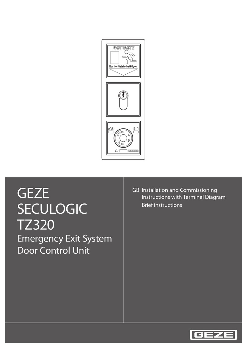
GEZE SecuLogic TZ320 Installation and operation manual

Material No. 132916 • Rev. 01-2009 • Drawing No. 35207-9-0955
GEZE SecuLogic Emergency Exit System
TZ320 Door Control Unit
Installation And Commissioning Instructions
With Connection Diagram
GB

2
Document information
Installation And Commissioning Instructions With Connection Diagram GEZE Door Control Unit
Document information
Document identification
Title: Installation And Commissioning Instructions With Connection Diagram GEZE SecuLogic Emergency
Exit System
TZ320 Door Control Unit
Material number: 132916
Revision state: 01-2009
Manufacturer
GEZE GmbH
Reinhold-Vöster-Str. 21 - 29
71229 Leonberg
Germany
Telephone: +49 7152 203-0
Fax: +49 7152 203-310
Internet: www.geze.com
Product markings in this document are possibly trade marks and are used here only for the purpose of
identification.
© GEZE GmbH. All rights reserved.

3
Installation And Commissioning Instructions With Connection Diagram GEZE Door Control Unit
1 In this document
1.1 Product description .........................................................................................................4
1.2 Other documents .............................................................................................................4
1.3 Symbols and markings .................................................................................................... 4
1.4 Abbreviations .................................................................................................................. 5
2 Safety and liability
2.1 Basic safety instructions .................................................................................................. 7
2.2 Target group and qualification ......................................................................................... 7
3 Installation and assembly
3.1 Requirements .................................................................................................................. 8
3.2 Install in-wall door control unit ......................................................................................... 8
3.3 Install the on-wall door control unit .................................................................................11
3.4 Change the lock cylinder ................................................................................................13
4 Commissioning
4.1 Requirement ...................................................................................................................14
4.2 Service mode .................................................................................................................14
4.3 Connect the service terminal ST220 with the door control unit ........................................15
4.4 Switch off the service terminal ........................................................................................15
4.5 System settings ..............................................................................................................16
4.6 Door control unit settings ................................................................................................17
4.7 Components settings ......................................................................................................23
4.8 Bus settings ...................................................................................................................26
5Operation
5.1 Control TZ320 door control unit via key-operated push button ........................................30
5.2 Open the doors and trigger off the alarm in case of an emergency .................................31
5.3 Cancel alarm ..................................................................................................................32
5.4 Read out the alarm memory via the service terminal ......................................................33
5.5 Read out fault report ......................................................................................................34
5.6 Read out alarm signal ....................................................................................................35
5.7 Power failure ..................................................................................................................36
5.8 Reset door control unit to default setting ........................................................................37
5.9 Display software version ................................................................................................37
6 Terminal connection diagram
6.1 Contents .........................................................................................................................39
6.2 Preface ..........................................................................................................................40
6.3 Markings ........................................................................................................................40
6.4 Power input ....................................................................................................................40
6.5 Door control units ...........................................................................................................41
6.6 GEZE bus ......................................................................................................................48
6.7 Safety circuit (indirect release) .......................................................................................50
6.8 Interlocking elements .....................................................................................................51
6.9 Emergency button ..........................................................................................................55
6.10 Key-operated push button ..............................................................................................57
6.11 Numerical code lock .......................................................................................................59
6.12 Terminal box ..................................................................................................................60
6.13 Locks .............................................................................................................................64
6.14 Revolving door drive system ...........................................................................................69
7Annex
7.1 Checklist for commissioning ...........................................................................................77
7.2 Glossary .........................................................................................................................78
7.3 Data sheets ....................................................................................................................79
7.4 Service menu - service terminal ST220 ..........................................................................82
4
Installation And Commissioning Instructions With Connection Diagram GEZE Door Control Unit
In this document
1 In this document
This instruction describes the installation and commissioning as well as the connection of
GEZE door control unit.
1.1 Product description
The GEZE door control unit is an integral part of SecuLogic escape route system and
serves for the control and monitor of electric interlocked emergency exits.
Furthermore, it offers a wide range of gateways to other products as well as systems.
Revolving door drive systems as well as motor locks, signalling device, e. t. c. can be
connected. Also, signal messages on superordinate factory master control systems or the
central visualisation can be forwarded via PC or tableau.
Intelligent functions can be realised between the door control units via the GEZE bus
system, e. g. sluice functions or the switching on and forwarding of fire alarm and burglar
alarm systems.
1.2 Other documents
Data sheets with technical data are included in the delivery of the components
respectively. You will find these data sheets and other documents in the internet by visiting
the website www.geze.de/SecuLogic.
1.3 Symbols and markings
Some information in this document are highlighted as follows:
Instructions
Requirements: As a prerequisite, there are conditions that must be fulfilled so that the subsequent action
steps can be carried out.
Here is something to do. This symbol indicates an instruction that contains only an
action step or action steps in warning notices, in which there is no particular sequence.
1. Multiple step instructions are marked by successive numbers.
Results of an action are marked by this arrow.
Important information
Text marked like this informs about special features.

5
Installation And Commissioning Instructions With Connection Diagram GEZE Door Control Unit
In this document
In this documentSicherheit und VerantwortungInstallation und MontageInbetriebnahmeBedienungAnschlussplanAnhang
Safety instructions
You will find basic safety instructions in a separate section (see page 7).
Section related safety instructions are marked as follows:
Section related safety instructions are divided into four danger levels, which are identified
by the signal word:
Standards conformity
1.4 Abbreviations
DANGER
A note on safety refers to dangers, their causes and consequences.
Here are measures to avoid danger.
Signal word Meaning
DANGER Warns against an imminent danger that leads to death or fatal injuries if it is
not avoided
WARNING Warns against danger that can lead to death or fatal injuries if it is not avoided
CAUTION Warns against danger that can lead to fairly serious or mild injuries
NOTE Warns against material damages
Marking to show that the product does not comply with the specified standard,
here "guidelines on electric locking systems of doors in the escape routes"
(EltVTR)
EltVTR
Abbreviation Specification
TZ320 Door control unit in bus technique
TZ322 Door control unit in the bus technique without emergency button
TZ323 Door control unit in the bus technique, rotated 180°
TZ320B Door control unit with illuminated emergency exit shield
TZ320S Door control unit with key-operated push button (connection via ribbon cable)
TZ320N Door control unit with integrated mains supply circuit
TZ320BSN Door control unit with illuminated emergency exit shield, key-operated push
button and integrated mains supply circuit
TZ320BS Door control unit with illuminated emergency exit shield and key-operated
push button
TZ320SN Door control unit with key-operated push button and integrated mains supply
circuit
AP On-wall
UP In-wall
BMA Fire alarm system
GMA Hazard alarm system

6
Installation And Commissioning Instructions With Connection Diagram GEZE Door Control Unit
In this document
RWA Smoke and heat venting system
GLT Building control
EMA Burglar alarm system
ZSU Time-switch
KZF Short-term release
NO Potential-free closer contact (normal open)
NC Potential-free opener contact (normal closed)
NT Mains supply circuit
SLE220 Signal light
SLH220 Alarm horn
BLE220 Flashing light
SHB220 Signal horn with flashing light
SCT320 Key-operated push button, single-pole reverse push button (two closers)
SCT221 Key-operated push button, single-pole push button (closer), expandable to
single-pole reverse push button (two closers)
SCT222 Key-operated push button with LED display, single-pole reverse push button
(two closers)
MLS Motor lock
HLS Handle lock
TST320 TZ control unit
NSA220 Emergency button
KL220 Terminal box
FTÖ Emergency exit opener
FS Falling lock
MA500 Holding magnet
TE220 Tableau unit
VAT220 Visualisation software
Abbreviation Specification

7
Installation And Commissioning Instructions With Connection Diagram GEZE Door Control Unit
Safety and liability
Zu diesem DokumentSafety and liabilityInstallation und MontageInbetriebnahmeBedienungAnschlussplanAnhang
2 Safety and liability
The GEZE door control unit was designed according to the state-of-the-art technology and
the accepted safety-related rules. However, there might be danger during installation and
use. Therefore, pay attention to the following instructions.
2.1 Basic safety instructions
The installation, commissioning and repairs must be carried out exclusively by an
electrician or an expert authorised by GEZE
Use only GEZE original parts for repair work
GEZE assumes no liability for damages resulting from unauthorised changes to the
system
Primary safety measures take place on site
The standards VDE 0100 and VDE 0815 must be observed during cable routeing
In order to avoid unauthorised inspections, do not leave the key in the key-operated
push button
An expert must check the doors with electric locking mechanism in the escape routes
once a year. The expert is to issue a certificate on the in-service inspection, which the
operator of the building supervisory board has to show on demand. Within the scope of
a maintenance contract, the checking can be carried out by a GEZE service technician
or a professional organisation authorised by GEZE.
Furthermore, GEZE recommends that the operator inspects the escape route system
monthly for identifiable damages and defects. Such damages and defects, if available,
must be repaired immediately by a GEZE service technician or a professional
organisation authorised by GEZE.
Intended use
The GEZE door control unit is designed to control and monitor electric-locked emergency
exits. External products may only be integrated after consulting GEZE.
Contrary to the intended use
The connection of products which were not expressly approved for use by GEZE is
contrary to the intended purpose.
2.2 Target group and qualification
The installation, assembly, commissioning and repairs must be carried out only by a
trained electrician or an expert authorised by GEZE.

8
Installation And Commissioning Instructions With Connection Diagram GEZE Door Control Unit
Installation and assembly
3 Installation and assembly
3.1 Requirements
Cable laying available in accordance with GEZE cable diagram
Circuit breakers as the primary cutting off plate cylinder on the mains-side
Compliance with the standards VDE 0100 and VDE 0815 for the cable routeing
Sabotage secured cable routeing according to VDE 0833 (on-wall cables in the steel
tube)
For the type of in-wall plug sockets installed near the door (base range 62.5 mm) with an
installation height top of floor of 850 mm up to a maximum of 1200 mm for the
emergency button
3.2 Install in-wall door control unit
These instructions describe the installation of an in-wall door control unit using the
example of TZ320BSN, as recommended by GEZE.
[1] Illuminated emergency exit shield
[2] Frame
[3] Mains supply circuit NET220
[4] Terminal strips
[5] Ribbon cable
[6] Control unit with emergency button TST320
[7] Key-operated push button SCT320
DANGER
Danger of electrocution
The installation and assembly must be carried out exclusively by an electrician or an
expert authorised by GEZE
Check that the cables are disconnected before the installation.
1
7
6
23
5
4

9
Installation And Commissioning Instructions With Connection Diagram GEZE Door Control Unit
Installation and assembly
Zu diesem DokumentSicherheit und VerantwortungInstallation and assemblyInbetriebnahmeBedienungAnschlussplanAnhang
1. Pass the power lead and ribbon cables through the in-wall plug socket.
2. Connect cable to the terminal strips in accordance with the connection diagram.
3. Connect and secure the mains supply circuit.
4. Connect the door control system with the key-operated push button and the key-
operated push button with the emergency exit shield using the ribbon cable.
850 - 1200
60
71
71
62,5

10
Installation And Commissioning Instructions With Connection Diagram GEZE Door Control Unit
Installation and assembly
5. Plug the terminal strips to the circuit board of the door control system.
6. Set jumper in accordance with the connection diagram (see page 44).
7. Install the door control unit.
8. Check the functional capability.
A
B
C
D
C
B
D
A

11
Installation And Commissioning Instructions With Connection Diagram GEZE Door Control Unit
Installation and assembly
Zu diesem DokumentSicherheit und VerantwortungInstallation and assemblyInbetriebnahmeBedienungAnschlussplanAnhang
3.3 Install the on-wall door control unit
These instructions describe the installation of an on-wall door control unit using the
example of TZ320BSN, as recommended by GEZE.
[1] TZ320BSN door control unit
[2] TZ323BSN door control unit
[3] Terminal strips
1. Open the housing.
12
3

12
Installation And Commissioning Instructions With Connection Diagram GEZE Door Control Unit
Installation and assembly
2. Install the wall bracket close to the door (height of the emergency button: 850 mm -
1200 mm top of floor).
3. Unscrew the covering of the mains supply.
4. Connect the 230-V circuit to the luster terminal of the mains supply circuit and screw
the covering.
5. Connect cable to the terminal strips in accordance with the connection diagram (see
page 44).
6. Plug the terminal strips to the circuit board of the door control system.
7. Set jumper in accordance with the connection diagram.
8. Secure loose cabling with cable clips.
9. Hook up the housing and bolt.
10.Insert the covering of the emergency button.
11.Check the functional capability.
850 - 1200

13
Installation And Commissioning Instructions With Connection Diagram GEZE Door Control Unit
Installation and assembly
Zu diesem DokumentSicherheit und VerantwortungInstallation and assemblyInbetriebnahmeBedienungAnschlussplanAnhang
3.4 Change the lock cylinder
1. Set the system on the service mode if it is in operation.
2. Dismantle the housing from the wall bracket.
3. Unscrew the key-operated push button
4. Unscrew the cylinder head screw and dismantle the lock cylinder.
5. Change the lock cylinder.
6. Insert a new lock cylinder and fasten with cylinder head screw.
7. Install the door control unit in the inverse order.
8. Check the functional capability.
The lock cylinder must meet the following standards:
Profile half cylinder 40 mm (30/10)
8-fold adjustable

14
Installation And Commissioning Instructions With Connection Diagram GEZE Door Control Unit
Commissioning
4 Commissioning
4.1 Requirement
Before the first commissioning of doors with electric locking mechanisms in the escape
routes, correlation with verification of suitability is to be confirmed by means of a certificate
issued by the manufacturer. Likewise, an expert is to establish if the electric locking
mechanism is installed properly and if it is operational (see page 77).
4.2 Service mode
The service mode must be engaged in order to set different parameters on the door control
unit.
4.2.1 Switch on the service mode
Requirements: There is no alarm.
The burglar alarm system is disconnected.
1. Insert the key into the lock of the key-operated push button.
2. Turn the key left and hold for approximately ten seconds.
LED 2 flashes green. LEDs 1 and 3 do not flash.
4.2.2 Switch off the service mode
Do not make adjustment nor go to the service menu for three minutes
Select end of service mode.
Door control unit is in normal state again.
12
3

15
Installation And Commissioning Instructions With Connection Diagram GEZE Door Control Unit
Commissioning
Zu diesem DokumentSicherheit und VerantwortungInstallation und MontageCommissioningBedienungAnschlussplanAnhang
4.3 Connect the service terminal ST220 with the door control
unit
The service terminal is connected with the door control unit via an infrared interface.
[1] Service terminal ST220
[2] Infrared interface on TZ320
1. Before covering the control unit, hold the service terminal and press the ON button for
approximately one second.
The service terminal is switched on.
2. Press the ESC button.
The first level of the service menu is displayed.
4.4 Switch off the service terminal
Do not press any button for two minutes.
The service terminal is switched off.
Service terminal ST220
Button Description Function
ON button Switch-on
ESC button Go back one menu level,
without taking on a new value
UP button Go one line upward
or increase the numerical value
DOWN
button
Go one line downward
or reduce the numerical value
RETURN
button
Select
or take on a new value
ON
X
21

16
Installation And Commissioning Instructions With Connection Diagram GEZE Door Control Unit
Commissioning
4.5 System settings
4.5.1 Set clock and date
In the service menu system setup > clock/date select the corresponding menu
item and set the values.
The adjusted value is displayed on the upper display row of the service terminal.
If several door control units are connected with each other via the bus, the adjusted
data of all connected door control units are transferred.
4.5.2 Set language
For the service menu, the following languages are available in the service terminal:
German (default setting)
English
In the service menu, select system setup > language > choice and set the
language.
The service menu is displayed in the selected language.
Menu "system setup > clock/date"
Menu item Submenu Submenu Choice
(Default setting)
Clock Hour Change value 0 - 23 (12)
Minute Change value 0 - 59 (00)
Date Day Change value 01 - 31 (01)
Month Change value 01 - 12 (01)
Year Change value 00 - 99 (09)
Weekday Change value –Monday - Sunday
(Thursday)
Automatic clock change
(summer/winter time)
Change value –On
Off
(Off)

17
Installation And Commissioning Instructions With Connection Diagram GEZE Door Control Unit
Commissioning
Zu diesem DokumentSicherheit und VerantwortungInstallation und MontageCommissioningBedienungAnschlussplanAnhang
4.6 Door control unit settings
4.6.1 Set short-term unlock
Duration: Duration of the short-term unlock
Abort: Exiting the short-term unlock by closing the door
Post trigger: Extending the short-term unlock through renewed short-term unlock
In the service menu, set TZ parameter > short-term unlock and make
adjustments for corresponding menu items.
The selected value is displayed on the upper display row of the service terminal.
Menu "TZ parameter > short-term unlock"
Menu item Submenu Choice
(Default setting)
Duration Change value 0s - infinite (10s)
Abort –Yes
No
(Yes)
Post trigger –
If Abort is set on No, the duration of the short-term unlock must not be set on
infinite.
In order to avoid an inadvertent continuous unlocking in highly frequented doors,
use an external control device for the short-term release.

18
Installation And Commissioning Instructions With Connection Diagram GEZE Door Control Unit
Commissioning
4.6.2 Set alarm
Pre-alarm: An acoustic signal that starts after a short-term release time elapses if the
door was not closed. The pre-alarm time ends if the door is closed. If the door is not
closed, the alarm is triggered off if the set time elapses
Alarm: An acoustic signal on the door control unit for the duration of the set alarm time.
Thereafter, there is a two-minute break before the alarm rings out again
Buzzer: Volume and sound of the alarm types
1. In the service menu, set TZ parameter > alarm setup.
2. Set times for pre-alarm and alarm.
3. Set buzzer for alarm, pre-alarm and sabotage.
The selected value is displayed on the upper display row of the service terminal.
Menu "TZ parameter > alarm setup"
Menu item Submenu Submenu Submenu Choice
(Default setting)
Alarm time Pre-alarm time Change value –0s - 10min (10s)
Alarm time Change value –10s - 2min (30s)
Buzzer Buzzer pre-alarm Volume Pre-
alarm
Change
value
0 - 15 (15)
Sound pre-alarm Choice Permanent
4s-interval
2s-interval
4 beep
2 beep
(2 beep)
Buzzer alarm Volume Alarm Change
value
0 - 15 (15)
Sound alarm Choice Permanent
4s-interval
2s-interval
4 beep
2 beep
(4s-interval)
Buzzer sabotage Volume
Sabotage
Change
value
0 - 15 (15)
Sound sabotage Choice Permanent
4s-interval
2s-interval
4 beep
2 beep
(4 beep)

19
Installation And Commissioning Instructions With Connection Diagram GEZE Door Control Unit
Commissioning
Zu diesem DokumentSicherheit und VerantwortungInstallation und MontageCommissioningBedienungAnschlussplanAnhang
4.6.3 Set inputs
Activities
The inputs of the door control units and terminal boxs can be set on the following activities:
Set activity for the door control unit
1. In the service menu, set TZ parameter > custom inputs.
2. For the corresponding input numbers, choose TZ input 1-3 >
activity TZ1-3 > choice and select activity (default setting: high-active).
The selected value is displayed on the upper display row of the service terminal.
Set activity for the terminal box
1. In the service menu, select system environment > KL > custom inputs.
2. For the corresponding input number, choose KL input 1-4 > activity KL1-4 >
choice and select activity (default setting: high-active).
The selected value is displayed on the upper display row of the service terminal.
Activity Specification
High-active The input is active if the input is closed (closer). 24 V is pending in the input
Low-active The input is active if the input is open (opener). 0 V is pending in the input
Disabled The input is inactive
Pay attention to the stepping sequence if an input is adjusted from high-active
to low-active or vice versa.
1. Set input on disabled.
2. Connect wires.
3. Set input on low-active or high-active.

20
Installation And Commissioning Instructions With Connection Diagram GEZE Door Control Unit
Commissioning
Configurations
The inputs of the door control units and terminal boxs can be set on the following
configurations:
Level: A permanent signal is active
Flank: An impulse is active
Set configuration for the door control unit
1. In the service menu, set TZ parameter > custom inputs.
2. For the corresponding input number, choose TZ input 1-3 > configuration
TZ1-3 > choice and select configuration.
The selected value is displayed on the upper display row of the service terminal.
Set configuration for the terminal box
1. In the service menu, select system environment > KL > custom inputs.
2. For the corresponding input numbers, choose KL input 1-4 >
configuration KL1-4 > choice and select configuration.
The selected value is displayed on the upper display row of the service terminal.
4.6.4 Set outputs
Contacts
The outputs of the door control units and terminal boxs can be set on the following
contacts:
Configuration Specification Interpretation
Sabotage ext. The signal message sabotage is triggered off,
sabotage alarm follows
Level
Unlock The system goes to the state unlocked Flank
Lock The system goes to the state locked Flank
Short-term unlock The system goes to the state short-term
unlocked
Flank
Burglar alarm
system
The signal message burglar alarm system is active Level
Time-switch The signal message time-switch is active Level
Fire alarm system The signal message fire alarm system is active Level
Motor lock Input for lock with the motor lock for door control
unit control or acknowledgement of alarms
Level
Handle Input for handle contacts for triggering the pre-
alarm when the handle is actuated
Level
Public holiday Time-switch is switched off in an active input Level
Contact Parameter Specification
Closer NO Contact closes
Opener NC Contact opens
Disabled –The output is not controlled
Other manuals for SecuLogic TZ320
2
Table of contents
Other GEZE Control Unit manuals

GEZE
GEZE IQ box KNX Quick start guide

GEZE
GEZE SecuLogic RWS TZ 300 Installation and operation manual

GEZE
GEZE IO 420 User manual

GEZE
GEZE TS 5000 E-ISM User manual

GEZE
GEZE GCVR 800 Touch Instruction manual

GEZE
GEZE Slimdrive SD User manual

GEZE
GEZE THZ User manual

GEZE
GEZE RSZ6 User manual

GEZE
GEZE GCVR 300 Touch T Instruction manual

GEZE
GEZE IQ box KNX HS User manual