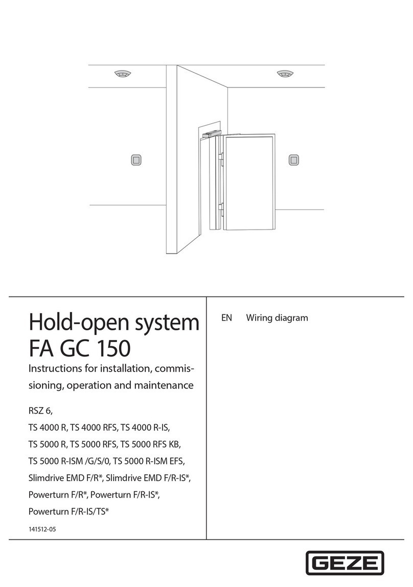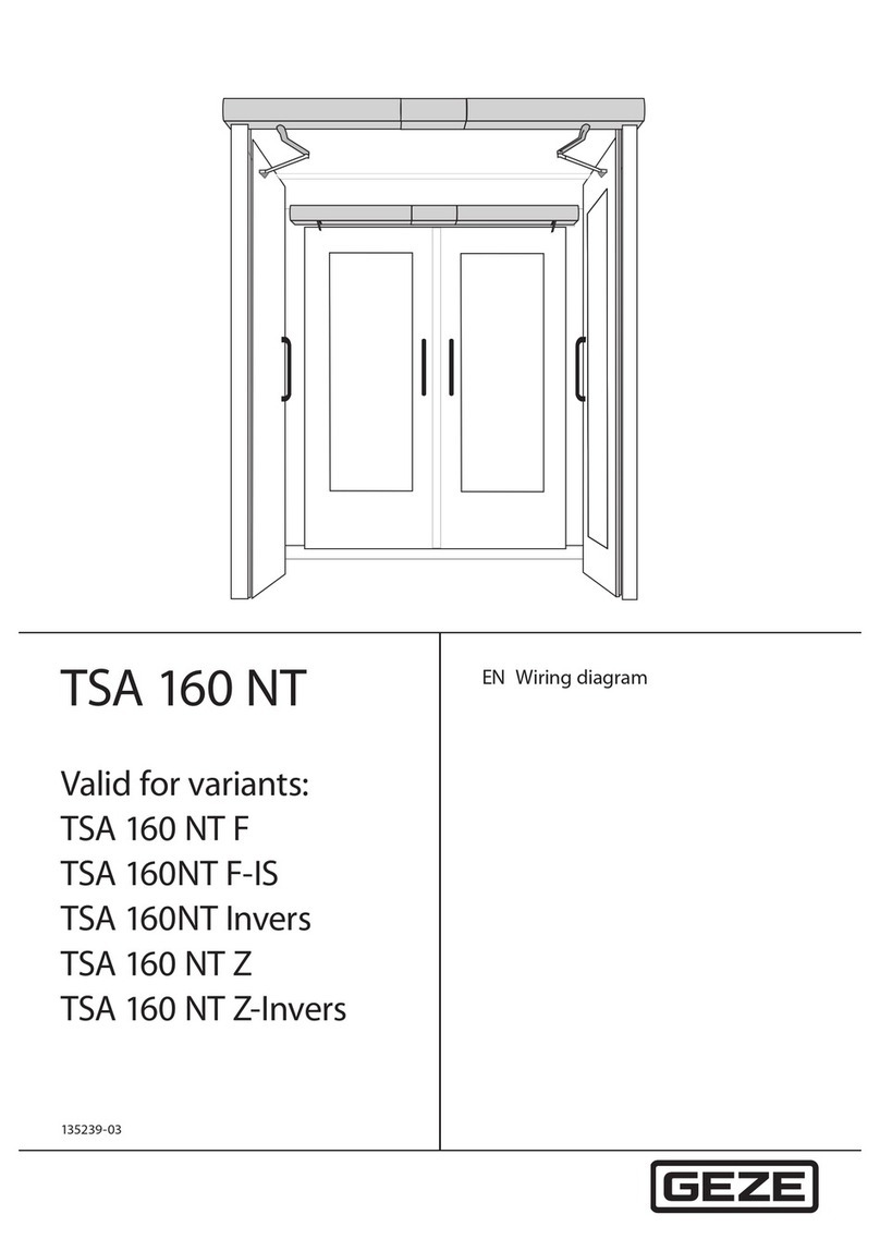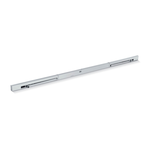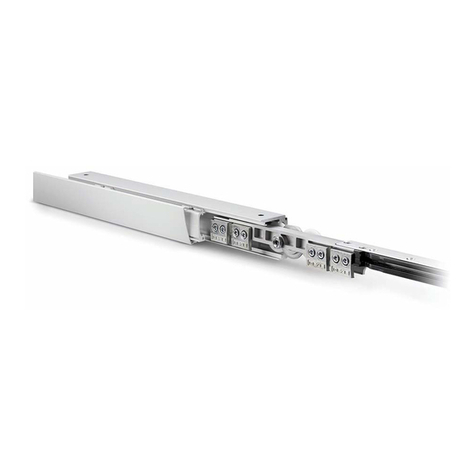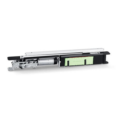
GEZE hold-open system FA GC 150
2
Contents
1 Symbols and illustrations......................................................................................................................................4
2 Notes............................................................................................................................................................................4
2.1 Installation and electrical connection of the hold-open system ...................................................................................................4
2.2 Installation of the lintel-mounted smoke switch..................................................................................................................................5
2.3 Protecting a smoke switch from contamination ..................................................................................................................................5
2.4 Disposal................................................................................................................................................................................................................5
3 Hold-open system FA GC 150..............................................................................................................................6
3.1 Function ...............................................................................................................................................................................................................6
3.2 Hold-open system with separate smoke control unit RSZ 6, RSZ 7...............................................................................................7
3.3 Integrated hold-open systems....................................................................................................................................................................8
3.4 Classication in accordance with EN 14637............................................................................................................................................9
3.5 Planning of re detectors and manual trigger switches....................................................................................................................9
3.5.1 Smoke detector or thermal detector ........................................................................................................................................................9
3.5.2 Number and installation of re detectors............................................................................................................................................ 10
3.5.3 Manual trigger switch...................................................................................................................................................................................11
4 Technical data.........................................................................................................................................................12
4.1 Hold-open system FA GC 150 ....................................................................................................................................................................12
4.2 Guidelines..........................................................................................................................................................................................................12
4.3 Power supply....................................................................................................................................................................................................12
4.4 Lintel-mounted smoke switch GC 151....................................................................................................................................................13
4.5 Wireless module GC 171...............................................................................................................................................................................14
4.5.1 “Operating” mode......................................................................................................................................................................................... 16
4.5.2 “Set up wireless connection” mode ........................................................................................................................................................18
4.6 Ceiling-mounted smoke detector GC 152............................................................................................................................................ 21
4.7 Ceiling-mounted thermal detector GC 153 ......................................................................................................................................... 22
4.8 Ceiling-mounted smoke detector ORS 142 ......................................................................................................................................... 23
4.9 Wireless ceiling-mounted smoke detector GC 172........................................................................................................................... 24
4.9.1 Signalling.......................................................................................................................................................................................................... 25
4.9.2 Battery replacement..................................................................................................................................................................................... 25
4.10 Wireless thermal detector GC 173........................................................................................................................................................... 25
4.10.1 Signalling .......................................................................................................................................................................................................... 26
4.10.2 Battery replacement..................................................................................................................................................................................... 26
4.11 Manual trigger switch UTA......................................................................................................................................................................... 27
4.12 Wireless input module GC 175.................................................................................................................................................................. 27
4.12.1 Signalling.......................................................................................................................................................................................................... 28
4.12.2 Battery replacement..................................................................................................................................................................................... 28
5 Wiring diagram...................................................................................................................................................... 29
5.1 Mains connection.......................................................................................................................................................................................... 29
5.1.1 Mains connection for protection rating I ...................................................................................................................................... 29
5.1.2 Mains connection for protection rating II ............................................................................................................................30
5.1.3 Mains connection for Slimdrive EMD F/R versions*.......................................................................................................................... 30
5.1.4 Mains connection for Powerturn F/R versions*.................................................................................................................................. 30
5.2 Ceiling-mounted detector ........................................................................................................................................................................ 30
5.2.1 Ceiling-mounted detectors GC 152 and GC 153 ................................................................................................................................ 30
5.2.2 Ceiling-mounted smoke detector ORS 142 ......................................................................................................................................... 33
5.3 Manual trigger switch or contact of the re alarm system............................................................................................................ 34
5.3.1 Manual trigger switch UTA......................................................................................................................................................................... 34
5.3.2 Contact to the re alarm system.............................................................................................................................................................. 35
5.3.3 Contact of the re alarm system and manual trigger switch UTA............................................................................................... 35
5.4 Wireless module GC 171.............................................................................................................................................................................. 36
5.4.1 Wireless ceiling-mounted detector GC 172 or GC 173 and/or wireless input modules GC 175 ....................................... 36
5.4.2 Wireless ceiling-mounted detector GC 172 or GC 173 – manual trigger switch or re detector contact wired........ 37
