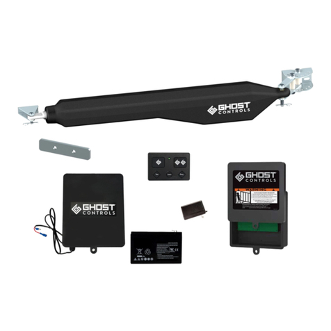
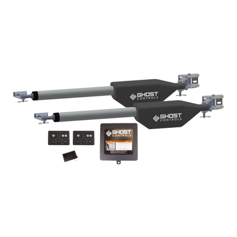
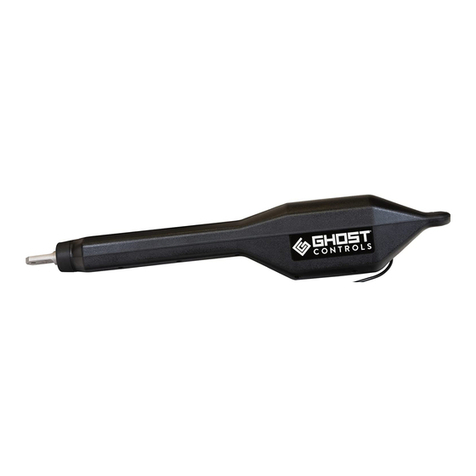
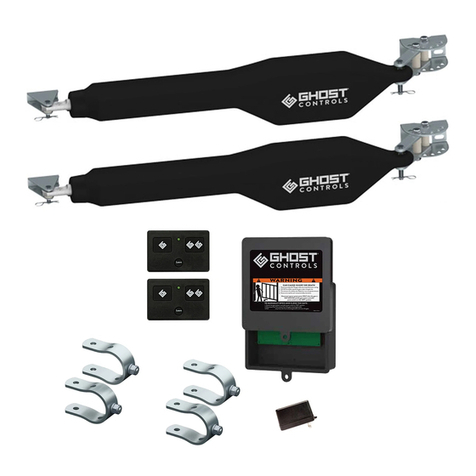
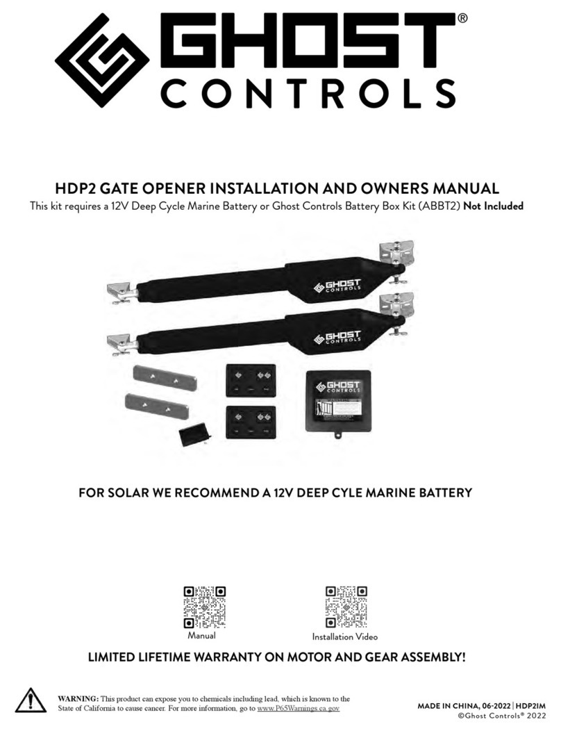
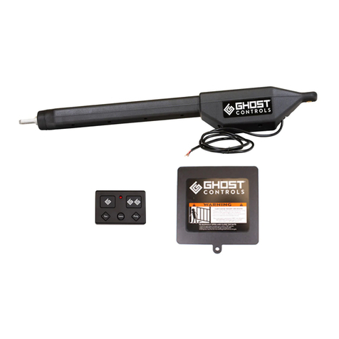
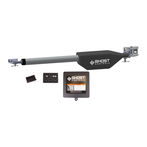
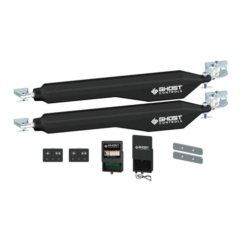
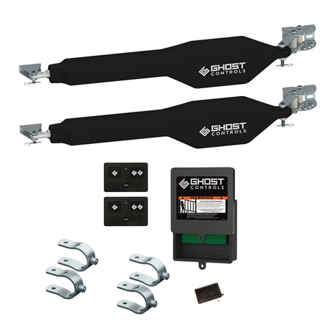
Ghost Controls DTP1XP Installation instructions

DTP1 GATE OPENER INSTALLATIONAND OWNERSMANUAL
A 12V BATTERYISREQUIRED TO OPERATE OPENER AND IS INCLUDED!
*If using solar you will need to add another 12V Battery to your Battery Box Kit.
©Ghost Controls®2020
WARNING: This product can expose you to chemicals including lead, which is known to the
State of California to cause cancer. For more information, go to www.P65Warnings.ca.gov

CONTACT US:
1572 Capital Circle NW, Tallahassee, FL 32303
www.ghostcontrols.com
For sales, product information, or to locate a retailer near you:
Call: 850-846-6400
Monday through Friday: 8:00–5:00 EST
For installation assistance and technical support:
Call: 850-898-1411
Monday through Friday: 8:00–5:00 EST
Product information, technical article, and installation videos can be found at:
ghostcontrols.com/help or
Ghostcontrols.com/Support/Installation-Video
2D T P 1 SIN G L E K I T
© G host Contr o l s ®2 0 2 0

CONTENTS
Installation and Owners Manual
Warranty Registration page 5
Operator Specifications page 6
System Safety page 7
System Overview page 10
Installation Planning page 12
Tools Needed page 15
Included Parts page 16
page 17
Control Box Installation page 22
Battery Installation page 22
Connecting Arm to Control Box page 24
Setup System Controller page 25
Front Mount Gate Bracket Installation page 28
Setting the Closed Limit page 32
Powering the System AC page 33
Powering the System Solar page 34
Setting the Auto Close Feature page 35
page 37
Control Box Installation page 42
Battery Installation page 42
Connecting Arm to Control Box page 44
Setup System Controller page 45
Front Mount Gate Bracket Installation page 48
Setting the Open Limit page 52
Powering the System AC page 53
Powering the System Solar page 54
Setting the Auto Close Feature page 55
Troubleshooting page 57
Connecting Optional Accessories page 58
Manual Gate Operation page 60
Accessories page 61
3
CONTENTS

BEFOREYOU BEGIN:
The Ghost Controls ABBT Battery Box with one 12V Battery is required to power the operator and is included with your
kit. If your adding solar to this gate opener you will need to add another 12V battery to the battery box. The battery box
will hold up to two 12V batteries.
Push-To-Open applications (gate that swings away from the property) will require the Ghost Controls push-to-open
bracket kit (AXPO).
If charging your system with the AC transformer, you will need to purchase a 16 gauge stranded, 2-conductor low voltage
wire to connect the transformer to the gate operator control board. Up to 1,000 ft. of wire can be used.
For installations farther than 1,000 ft. from an AC power source, the Ghost Controls 10 Watt Solar Panel Kit (AXDP)
can be used to charge the battery. Up to 30 Watts of solar power can be used.
CUSTOMIZING YOUR GATE:
Information on additional accessories shown below can be found on the accessory page 61 or visit
www.ghostcontrols.com
INCLUDED IN DTP1 AND DEP2 KITS
ADDITIONAL ACCESSORIES
12Vbattery required and included
Opens gates up to 20 ft. or 1,000 lbs.
per gate leaf
Low Voltage Wire
(AXLV)
Wireless Vehicle Sensor
(AXWV)
Wireless
Keypad (AXWK)
used for exit
of property
Safety Placards
DTP1
Operator Arm
5 Button
Transmitter
(AXP1)
3 Button
Transmitter
(AXS1)
Water Resistant
Transmitter
(AXR1)
4D T P 1 SIN G L E K I T
© G host Contr o l s ®2 0 2 0

PROTECT YOURINVESTMENT!
Get An Additional 6 Months Warranty when you register
your product(s) atghostcontrols.com.
WARRANTY
REGISTER ONLINEWWW.GHOSTCONTROLS.COM
NOTE
If you’re unable to access the internet please fill out the warranty form below and mail in to us at Ghost Controls
1572 Capital Circle NW, Tallahassee, FL 32303
First Name:__________________________________________ Last Name: _________________________________
Street:___________________________________________________________ Apt. #: ___________________________
City :__________________________________________ State:_________________________ Zip: _______________
Phone Number: ___________________________________ Email Address: _________________________________
Items Purchased:
DTP1
DEP2
Where did you buy your gate opener system? (please include a copy of your receipt)
Type of gate you are using?
Chainlink Ornamental Tube
Approximate Gate Weight:___________________ pounds per leaf
Approximate Gate Length:___________________ feet per leaf
Type of Application:
Farm Home Business
Item Serial Number:___________________ Item Serial Number: ___________________ Manufacturer Date:__________________
Did you purchase any accessories? (Please list below)
5
D T P 1 SINGLE K I T
© G host Controls®2 0 2 0

6S P E CIF I C A TION S
© G host Contr o l s ®2 0 2 0
SPECIFICATIONS
Compliance: The operator is system certified to be in compliance
with UL325 Standard, 7th Edition
System Operating Voltage: 12 VDC
System Battery Type: Battery Box Kit (ABBT) 1 battery is included
System Current: 1-2 Amps is typical when active.
Standby is 20 milliamps
Operator Arm Maximum Stroke Distance: 23"
Maximum Gate Length: 20'
Operator Opening Speed: 90 degrees in approximately 15 seconds
Maximum Operator Opening Range: 110 degrees
Linear Actuator Operating Temperature: -5°F to 160°F
Maximum Gate
Length and
Weight
Max
900 lbs.
800 lbs.
700 lbs.
600 lbs.
500 lbs.
400 lbs.
350 lbs.
325 lbs.
300 lbs.
5' 6' 8' 10' 12' 14' 16' 18' 20'
DTP1 DTP1
DTP1
DTP1
DTP1
DTP1
DTP1
DTP1
DTP1
1000 lbs.
SPECIFICATIONS
DTP1 GATE OPERATOR KIT

7
SYSTEMSAFET Y
© G host Controls®2 0 2 0
This manual contains important safety precautions and
warnings for both the installer and end users or consumers
of this automatic gate opener system. The following warn-
ings and safety are intended to apply to the most common
applications but may not apply to all possible installation
and applications for these products. To reduce risk of
injury or death:
I. Carefully read and follow all safety precautions,
warnings, installation and operating instructions.
II. DO NOT ALLOW CHILDREN TO OPERATE
GATE CONTROLS. Do not allow children or pets
to play near the gate opener system. Keep all gate
control accessories such as remote transmitters,
keypads, and push buttons out of reach of children
and store in a secure area when not in use.
III. Understand how to disconnect the power and
manually open the gate (beginning on page 60)
BEFORE you begin using the gate opener system.
If you are unsure of any of these steps, please con-
tact GHOST CONTROLS®Technical
Support at 850-898-1411 or online at
ghostcontrols.com/help
IV. Disconnect the gate operator from the gate only
when the gate is not in motion and the opener
V. Moving gates can be dangerous. No one, including
people or animals, should cross the path of a moving
gate. Maintain a safe distance from moving parts
and avoid any areas where hands or fingers could
be pinched.
VI. Become familiar with potential entrapment zones as
shown below and avoid these areas when the gate is
turned on.
VII. The gate opener system must be installed only
in applications that it is specifically designed for
including: frequency of use, length, and weight
of the gate.
VIII. Install the gate operator system on the inside of
the property, gate, or fence line to prevent public
access to it. Most applications are installed in a pull-
to-open configuration so that the gate opens into
the property and away from any public roads.
IX. The control board for the gate operator system
should be protected from unauthorized access
inside the control box to prevent tampering or
adjustments to its setting once installed. The
control box is designed so that a padlock can be
attached to keep the box securely closed. An
accessory Clevis Pin (AXLC) is available for
purchase to secure the operator(s) to the post with
a padlock.
X. Keypads and push-buttons to activate the gate
operator system must be a minimum of 10'away IN
DIRECT LINE OF SIGHT VISIBILITY TO THE
GATE so that the user can verify that any potential
entrapment areas are clear of potential
obstructions.
XI. The included warning signs must be attached to
each side of the gate to alert the public of the
automatic gate operator system. Please contact
GHOST CONTROLS® Technical Support for
replacement signs if yours become damaged.
XII. While the gate is moving do not drive into the gate
area to prevent entrapment and potential damage
to your vehicle, gate, AND the gate opener system.
XIII. Do not attempt to “race the gate” by driving
through the gate while it is opening or closing. This
is extremely dangerous and can cause damage to
your vehicle, gate, AND the gate opener system.
XIV. Maintain the gate and the gate opener system to
make sure that the gate continues to swing freely
and is level throughout the entire swing path. The
gate hinges should be lubricated regularly, the
condition of the battery checked every few
months, and all connections checked no less than
an annual basis.
XV. In the event that you sell the gate opener system or
your property with a system installed, please
provide these instructions to the new owners.
The most recent version of these instructions
can be found on our support website at
ghostcontrols.com/help
SYSTEM SAFETY
GATE OPENERSYSTEMS
8SYSTEMSAF E T Y
© G host Contr o l s ®2 0 2 0
VEHICULAR GATE STANDARD
We recommend that all vehicular gates be constructed
and installed in accordance with Active Standard ASTM
F2200, Standard Specification for Automated Vehicular
Gate Construction. For more information on this standard,
contact ASTM directly at http://www.astm.org/Standards/
F2200.htm.
WARNING SIGNS
The included warning signs must be installed on both the
inside and outside of the gate.
! !
©GHOST CONTROLS 2016
1. Persons are to keep clear! The gate is able
to be moved without prior warning.
2. DO NOT let children operate the gare or
play in the gate area.
3. Persons are to operate the gate only when
the gate area is in sight and free of people
and obstructions.
dnalaunams’resuehtdaeroterasnosreP.4
.snoitcurtsniytefas
WARNING
ALARM
Your GHOST CONTROLS®Gate Operator system
includes an audible alarm. This alarm will continue to
sound for 5 minutes when two sequential obstructions
are detected during gate travel per UL325 safety
standards or until one of the following occurs:
The gate operator receives an intended signal from a
hard wired entry/exit source such as a push button or
a wired keypad. Note that wireless transmitters and
wireless keypads cannot deactivate the alarm.
Th
again at the main power switch in the control box.
NOTE
The alarm may also be used as audio feedback for other
modes of operation under normal operation.
SWING GATE PROTECTIONAND
ENTRAPMENT ZONES
As specified in Gate Operator Safety Standard, UL325
(30A 1.1) 7th Edition, all gate operators must include
two independent means of entrapment protection. All
GHOST CONTROLS®Automatic Gate opener systems
meet this standard as indicated on the product packaging
through the following:
1. TYPE A Inherent.
2. Number one above AND either of the following two
options:
A. TYPE C Inherent force limiting.
B. TYPE B1 and B2 monitored contact and non-
contact sensors.
If you have questions about compatibility of third
party safety devices, please contact GHOST
CONTROLS®technical support for assistance
at ghostcontrols.com/help.
Refer to the monitored photo eye instructions for proper
placement of the sensors. Proper installation of these
sensors is critical to avoid false tripping while gate is in
motion and to reduce potential entrapment.
CAUTION
Extreme caution must be exercised when automatic
gate opener system is in operation, regardless of which
safety systems are installed and in use.

9
SYSTEMSAFET Y
© G host Controls®2 0 2 0
ENTRAPMENT AREA NOTES
Between gate and post Keephands, feet, and pets away from this area when gate is in motion.
Pinch point between opener and gate Keephands, feet, and pets away from this area when gate is in motion.
Path of the moving gate All one zone
Leading edge of gate and pinch point
between gates in a dual gate installation
The leading edge of the gate in motion can easily cause injury to
people, pets, or livestock, and will damage property including
vehicles if it comes into contact with them.

10 SYSTEM O VERVIEW
© G host Contr o l s ®2 0 2 0
1. This gate operator is only intended for use on gates
intended for vehicular access and is not intended for
pedestrian gate applications. Pedestrians mustuse a
separate entrance.
2. The GHOST CONTROLS®Automatic Gate Opener
can be installed on a pull-to-open application with the
items included in the kit. For push-to-open applica-
tions you will need to purchase the required Push-To-
Open (item AXPO) bracket kit from your local retailer
or visit ghostcontrols.com/shop or contact GHOST
CONTROLS®Sales at 850-846-6400 to purchase.
3. This GHOST CONTROLS®Automatic Gate Opener
features a patent-pending SafeForce®power limiting
feature that doesn’t require Photo Eyes for entrapment
protection in most applications of a properly installed
gate. During installation, you may instead choose to use
external monitored safety devices such as non-contact
photo eyes (item AXPE sold separately) and will need
to enable this setting on the mainsystem controller
during setup.
The operator can be used on a variety of gate types,
but CAN NOT BE USED ON SOLID OR WOOD
PANEL GATES. Solid panel gates have a higher
resistance to wind and may result in damage to the
automatic gate operator.
5. All GHOST CONTROLS®Automatic Gate Operators
include automatic reversing safety features that will
make the gates stop and reverse direction within 2 sec-
onds of encountering an obstruction. There is a manual
setting on the main gate operator control board labeled
Force Setting that adjusts the sensitivity of this feature.
6. This GHOST CONTROLS®Automatic Gate
Operator can be enhanced with additional GHOST
CONTROLS®accessories such as our remote
transmitters, keypads, and all other accessories,
sold separately. (Accessories see page 61).
The GHOST CONTROLS®technical support
team is happy to assist in verifying compatibility
of any products not oered by GHOST
CONTROLS®. For additional assistance, please
contact GHOST CONTROLS®Technical support
ghostcontrols.com/help or by calling 850-898-1411.
7. Check all local building codes and ordinances prior to
installing this automatic gate operator system to make
sure your planned installation is in compliance.
8. Your gate must be in good working condition before
installation of the automatic gate operator system and
meet the following criteria:
A. GATE CAN NOT USE WHEELS for support or
drag along the ground at any point in the opening
or closing cycle.
B. GATE SHOULD BE LEVEL, PLUMB, AND
MOVE FREELY IN BOTH DIRECTIONS
WHEN MINIMAL FORCE IS APPLIED IN
THE OPENING OR CLOSING DIRECTION.
C. Gate should NOT open uphill or downhill.
9. The vehicular entry gate system must be installed
in alocation that prevents entrapment by providing
when opening and closing.
SYSTEM OVERVIEW
IMPORTANT INSTRUCTIONS
Thank you for choosing a GHOST CONTROLS®Automatic Gate Opener system, the most innovative gate opener systems
available for residential applications on the market today. This manual will guide you through the proper installation and main-
tenance methods. To reduce the risk of injury or death: READ, UNDERSTAND, AND FOLLOW ALL INSTRUCTIONS
CAREFULLY AND COMPLETELY. Following these directions is critical to a successful and safe operating environment.

11
SYSTEM O VERVIEW
© G host Controls®2 0 2 0
10. When planning asystem that will allow entry from a
busy road or highway, make sure the system is placed
11. Swing gate systems must not open into public access
areas or into the road which could cause collision with
a moving vehicle.
12. Test the gate operator monthly. The gate MUST
reverse on contact with a rigid object or stop when
an object activates the non-contact sensors. After
adjusting the force or the limit of travel, retest the gate
operator. Failure to adjust and retest the gate operator
properly can increase the risk of injury or death.
13.SEPARATE PEDESTRIAN GATE IS REQUIRED!
14. Single or dual gate operation based on the size of your
opening, gate specifications, and operator system
capacities.
A. Dual gate operations require trenching across
the driveway so that the power cable for the sec-
ondary gate operator can be buried. (shown in
diagram below)
B. The power cable should always be enclosed
in PVC conduit for protection, including
when buried across the driveway in dual
gate applications.
15. Swing direction of gate(s). The image (shown in dia-
gram below) indicates the more common “Pull-to-
Open” installation and the less common “Push-to-
Open” installation.
16.Vehicle Sensors should NOT be used on properties
that contain livestock or animals.
17.SAVE THESE INSTRUCTIONS.
TRENCH
Pedestrian Gate

12 P L A NNING
© G host Contr o l s ®2 0 2 0
INSTALLATION VIDEO CAN BE FOUND AT GhostControls.com/Support/Installation-Video
PREPARE THE GATE
Proper installation, care, and ongoing maintenance of the gate is critical to increased usage life of the automatic gate operator
system. The following items should be considered and addressed if needed PRIOR to installation of the automatic gate
operator system:
1. The gate must swing freely throughout its entire range of motion (fully open to fully closed) remaining plumb and level. The
gate should not swing uphill or downhill when opening or closing.
2. The gate must not drag on the ground at any point during its motion and MUST NOT BE SUPPORTED BY
ROLLERS OR WHEELS. Guy wires should also not be used to support the gate.
3. Extremely heavy gates that exceed 200 lbs in weight per leaf should be mounted with ball bearing hinges that include
grease fittings.
4. The gate should be mounted to a very stable post or column that is secured in the ground with concrete. Securing the post
w
through its range of motion. Installation is not recommended on any post or column that is not installed in the ground with
concrete.
5. The front mount of the gate operator should be attached to the gate securely. This may require modifications to the gate
design or surface to maintain this secure mounting location.
6.
hindrance.
LEVEL
CONCRETE THE POSTS
IN THE GROUND
INSTALLATION PLANNING
SITE PLANNING SITE

13
P L A N NING
© G host Controls®2 0 2 0
NOTE
Push-to-Open installations REQUIRE an accessory Push-to-Open bracket kit (AXPO).
7. Mounting location on gate and support post, column, or wall.
A. Wooden posts should be at least 6"x6" in size and set in concrete.
B. Metal round posts should be at least 3"in diameter and set in concrete.
C. Metal square posts should be at least 4"x 4" in size and set in concrete.
D. Additional mounting bolts may be required if the included bolts are not at least 1"longer than the diameter of
the post.
8. Location and mounting point of control box and battery box. Arm cable length determines how far away from operator arm
that you can mount the control box. THE ARM CABLE CANNOT BE SPLICED OR EXTENDED. PLEASE CALL
9. Power source to charge the battery (Solar Power vs. AC Power via transformer)
A. Never use Solar Panels AND an AC transformer on a gate system at the same time or you will damage the
main control board and void any warranty.
B. The AC transformer is designed for indoor use and must be protected in a weather resistant box (that meets
code in your area) if it will be mounted outside.
10. If choosing to use an AC transformer for the battery recharging power source, you should consider the distance from an
outlet to your battery box.
A. No more than 1000 feet of low voltage wire may be used between the AC transformer and the gate
operator system due to electrical losses. If your application exceeds 1000 feet in distance, you must
use Solar Panels for your power source to recharge the batteries.
B. WIRE WILL NEED TO BE PURCHASED SEPARATELY. We oer and recommend 16 gauge
low voltage wire.
C. The transformer should be on a circuit that is protected by a GFCI plug or breaker.
11. If choosing to use a Solar Panel for the battery recharging power source, you should consider the distance from an outlet to
your battery box.
A. No more than 100 feet of low voltage wire may be used between the Solar Panel and the control box.
B. WIRE WILL NEED TO BE PURCHASEDSEPARATELY. We oer and recommend 16 gauge
low voltage wire.
C. Solar Panelshould face south away from trees, and other obstructions that would inhibit getting full sun.
12. How to exit the property and trigger opening operation of the gate (push button, remote transmitter, keypad, or vehicle
exit wand).

14 P L A NNING
© G host Contr o l s ®2 0 2 0
DETERMINE MOUNTING LOCATION ON GATE ANDSUPPORTBAR
You must determine where to mount the gate operator vertically on your gate system. Your gate MUST HAVE A
HORIZONTAL BAR ON THE GATE TO MOUNT THE FRONT OF OPERATOR TO. Each gate is unqiue and Ghost
Controls does not provide this in the kit.
The following three options should be considered when
planning your installation:
TOP MOUNTING — The gate operator is not
recommended to be mounted to the top of the gate
because the operator may cause twisting or flexing of
the gate while in motion.
CENTER LINE MOUNTING — This is the most
common and recommended method for mounting an
operator to the gate system.
BOTTOM MOUNTING — The gate operator must
does not come in contact with standing or flowing water
which will damage the system. This mounting location
may cause undesirable twisting or flexing of the gate
while in motion.
OPERATOR REARMOUNT INSTALLATION CONSIDERATIONS
The GHOST CONTROLS®Automatic Gate Operator system is designed for installation on rectangular, square, or round
posts (for 3"or 4"AX3R AND AX4R ROUND POST ADAPTER ACCESSORIES) or
columns. The rear bracket must be level and secured to the mounting post or column with bolts, nuts, and washers because
this bracket will experience a tremendous amount of force during operation of the automatic gate operator. Proper position-
ing of the rear mounting bracket is critical because it determines:
Leverage and stability of the operator as it applies force to move the gate
Necessary clearance between the operator in both the closed and open positions
For PULL-TO-OPEN installations, PLEASE GO TO PAGE 17.
For PUSH-TO-OPEN installations, PLEASE GO TO PAGE 37.
Top Mount
Center Mount
Bottom Mount

15
TOOLS NEEDED
©Ghost Controls®2020
Wire Strippers/Cutters
Level
Corded/Cordless Drill
Standard or
Metric Wrenches
Tape Measure
Standard or Metric
Socket Set
5/16" Drill Bit
7/32" Drill Bit
7/16" Drill Bit
(longer than diameter
or thickness of post)
Clamp
Phillips Head
Screwdriver
TOOLS NEEDED

16 P A R T S I NCL U D E D
© G host Contr o l s ®2 0 2 0
INCLUDED PARTS IN KIT
Front Mounting Hardware:
Rear Mounting Hardware:
Control Box
Gate Mounting Hardware:
Gate and Front
Mount Hardware
Post and Rear Mount Hardware
OR
AC Transformer in DTP1Kit:
Opener Arm:
Control Box Mounting
5 Button Remote:
10W Solar
Panel DTP1XP Kit:
Estate Bracket (Qty 1)

17
© G host Controls®2 0 2 0
RTY
The dimensions and step-by-step instructions that follow are for mounting the GHOST CONTROLS®Gate Operator in
a installation system to a decorative metal gate that swings into property.
STEP 1. Establish and mark the horizontal center lines of the gate and the postfor proper
alignment of gate brackets.
NOTE
This center point will be used
for mounting the post bracket
in STEP 4.
PULLTO OPENINSTALLATION
OPERATOR ARM INSTALLATION
si
o
n
s a
n
d s
t
e
p
-
b
y
-
s
t
e
p
i
n
s
t
r
u
c
t
i
o
n
s
t
h
a
t
f
o
fof
l
l
o
w a
r
e
f
o
fof
r
m
o
u
n
t
P
E
R
A
T
ATA
O
R
AR
M
I
N
S
T
AL
TALT
L
A
TIO
ATIOA
N
NOTE
Wheels cannot be used with
any Ghost Controls®gate
opener system!
For gates weighing over 200
lbs. ball bearing hinges are
recommended.
Operator is not for use on
solid panel privacy gates.

18
© G host Contr o l s ®2 0 2 0
STEP 2. Post bracket pre-assembly.
Insert the M10x1.5x75mm bolt and M10 washer through the hole that is closest to the post on the post bracket. Bolt should
then go through first pivot bracket, pivot spacer, second pivot bracket, and exit bottom hole of post bracket as shown below.
Fasten a M10 washer and M10 locknut on the end of the bolt. DO NOT overtighten the nut because the post bracket may
need to be adjusted later.
STEP 3. Clamp post bracket to post foralignment.
After the post bracket is pre-assembled and the horizontal centerline has been marked on the post as referred to in
STEP 2 and 3, proceed to CLAMP THE POST BRACKET TO THE MARKED CENTER LINE on the post.
Assembled
Exploded
CL

19
© G host Controls®2 0 2 0
NOTE
For round wooden post installations we recommend notching the wooden post for proper installation of the post bracket.
Follow the diagram for proper notching of a round post.
NOTE
AX3R AND AX4R round post adapter accessories (sold separately). See
illustration using the round post adapter below.
4.5" Height
4-3/8" Width
(4" minimum)

20
© G host Contr o l s ®2 0 2 0
STEP 4. Verifying minimum of 4˝ Gate Clearance and finishing rear post mount bracket assembly.
If the clearance is less than 4˝, you will need to adjust the pivot brackets so that you have at least 4˝ of clearance.
Once the clearances are correct, place the secondary bolt into the pivot bracket as shown. Insert the M10x1.5x75mm bolt
and M10 washer through the post bracket hole, then first pivot bracket, pivot spacer, second pivot bracket, and exit out
bottom hole of post bracket as shown below. Fasten a M10 washer and M10 locknut on the end of the bolt. Finish by
tightening both bolts on post bracket.
Adjust position
as necessary
Adjust position
Minimum Distance
as necessary
>4.0
This manual suits for next models
1
Table of contents
Other Ghost Controls Gate Opener manuals

Ghost Controls
Ghost Controls DTP1 Installation instructions

Ghost Controls
Ghost Controls TSS1 Installation instructions

Ghost Controls
Ghost Controls HDP1 Installation instructions

Ghost Controls
Ghost Controls ZombieLock User manual

Ghost Controls
Ghost Controls HDP1 Installation instructions

Ghost Controls
Ghost Controls DEP2 Installation instructions

Ghost Controls
Ghost Controls TSS1 User manual

Ghost Controls
Ghost Controls Ghost Pro LSM1 Installation instructions

Ghost Controls
Ghost Controls Ghost Pro Series Installation instructions

Ghost Controls
Ghost Controls HDP2 Installation instructions