1
0850EN May 2020
User and maintenance manUal
HigH or low temperature HiuswitH tHermostatic
control ge556Y320-321-322-323
ge556-4 series
1. General information
GE556Y320, 321, 322 and 323 HIUs enable metering thermal energy consumptions when heating and the production of Domestic
Hot Water (DHW) in modern autonomous systems with heat centralized production (eg. teleheating).
HIUs are controlled thermostatically by means of a 3-way priority valve.
Thermostatic control provides for the lowest return temperature when producing hot water.
1.1 Warnings
• Installation must be carried out by qualied personnel authorized by the building administration body. Comply with the regulations
in terms of use (installation, tting, etc...), operation, re-gauging and replacement of metering units. Also refer to assembly instructions
included with every metering unit.
• Risk of scalds and electric shocks. Only qualied personnel authorized by the building administration body should access the HIU.
Misuse may cause serious injuries to people and damage the system.
• An excessive temperature of the Domestic Hot Water may cause scalds to people; too cold water may lead to undesired bacterial
growth within the hot water system.
• Some HIU parts may overheat, do not touch them.
• Before connecting the HIU to the power line, make sure it has been properly lled with water. Starting the HIU without water inside
may damage the circulator and the HIU.
• When starting up the HIU, make sure no one uses the system water till the water temperature has been adjusted in order to prevent
scalds.
• To prevent polluting agents from entering the system, rst open the primary circuit valves and then the return valves when starting
up the HIU. Open the valves slowly to prevent pressure peaks.
• Do not cut o the electric power from the control panel. This may damage the circulator, the valve actuators, etc...
• The cleaning frequency of the sanitary water exchanger strongly depends on the hardness of the supply Domestic Cold Water.
• With water hardness values higher than 15°f we recommend using anti-scaling devices to be selected based on water characteristics.
• To enhance the resistance to limestone crusting, we recommend adjusting the sanitary water temperature at a value very close to
the value of actual use.
• When installing the HIU to control a low temperature zone, include a low-temperature safety thermostat on the controlled zone.
• Clean the sanitary water exchanger at the end of the rst year; then, based on the limestone crusting status, this period can be
extended to two years.
• The HIU can be used in closed boiler rooms for operation with non-aggressive uids (water, glycol-based water in compliance with
VDI 2035/ÖNORM 5195).
• The electrical installation must be done by qualied personnel, respecting the current legislation and Standards.
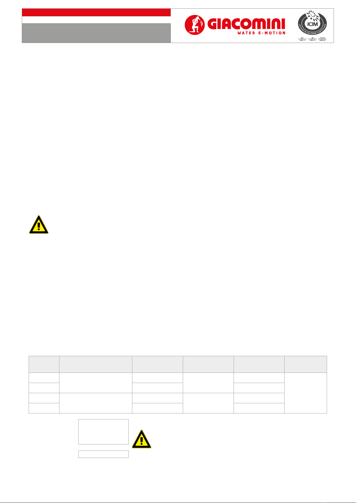
1.2 Versions and product codes
Product code Type Number of
exchanger plates Heating side power DHW exchanger
nominal power
Template with
valves
GE556Y320 High temperature heating and
DHW production
30 plates 21 kW 56 kW
GE551Y075
GE556Y321 40 plates 67 kW
GE556Y322 Low temperature heating and
DHW production
30 plates 10 kW 56 kW
GE556Y323 40 plates 67 kW
Warning.
• Every HIU includes:
- a label with the HIU model identication data;
- a label proving its compliance with electric and hydraulic tests;
• Every HIU is identied by a serial number both inside and on the packaging.