Giacomini GE556Y403 User manual

1
Giacomini S.p.A.
Via per Alzo 39, 28017 San Maurizio d’Opaglio (NO) Italia
consulenza.prodotti@giacomini.com
+39 0322 923372 - giacomini.com
GE556-2
Datasheet/Instruction
1071EN 05/2022
047U59108
GE556Y403/406 heat interface
units with electronic regulation
and adjustable tail pieces
The GE556Y403 and GE556Y406 heat interface units (HIU) allow the metering of heat energy consumption for heating and
the production of DHW (Domestic Hot Water) in modern autonomous systems with centralised heat production (e.g. district
heating).
The management of the HIUs parameters is completely electronic.
This allows signicant energy savings, minimizing the ow demand from the primary circuit and reducing the return temperature.
The various parameters can be set via remote control which also performs the function of programmable chronothermostat.

2
Giacomini S.p.A.
Via per Alzo 39, 28017 San Maurizio d’Opaglio (NO) Italia
consulenza.prodotti@giacomini.com
+39 0322 923372 - giacomini.com
Technical data
• Max. working temperature: 90 °C
• Max. working pressure: 10 bar
• Temperature range of the secondary heating circuit:
- low temperature: 25÷45 °C
- high temperature: 25÷85 °C
• Temperature range of the secondary DHW circuit: 30÷60 °C (Set-Point 50 °C)
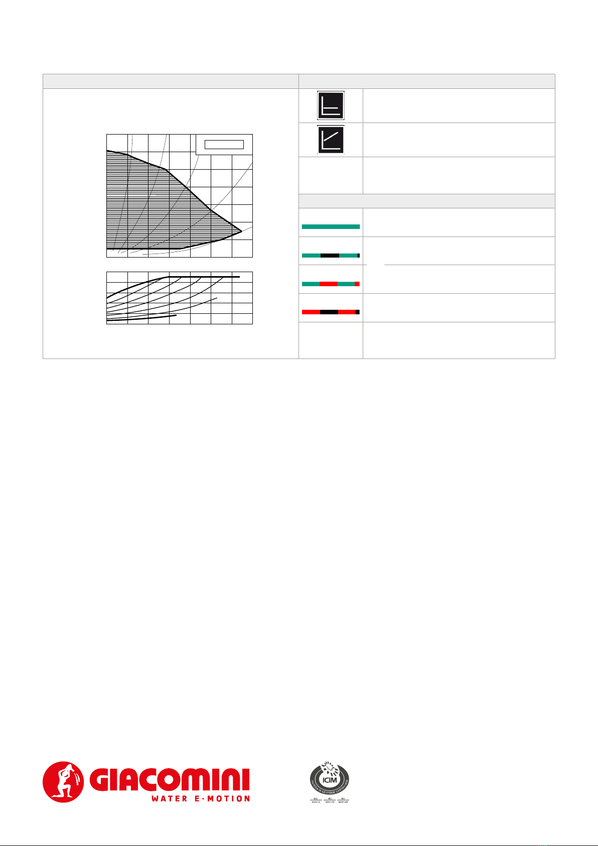
• Nominal ow rate on primary circuit:
1070 l/h @ 75 °C for 58 kW
1150 l/h @ 75 °C for 67 kW
WARNING. The satellite can be used in closed boiler rooms for operation
with non-aggressive uids (water, glycol-based water in compliance with VDI
2035/ÖNORM 5195).
WARNING. Max. working differential pressure for the primary circuit = 4 bar
(priority valve)
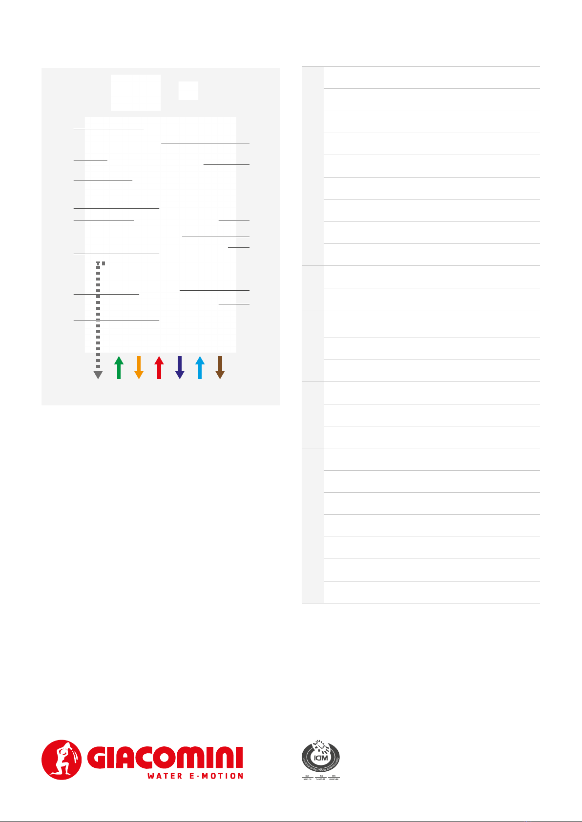
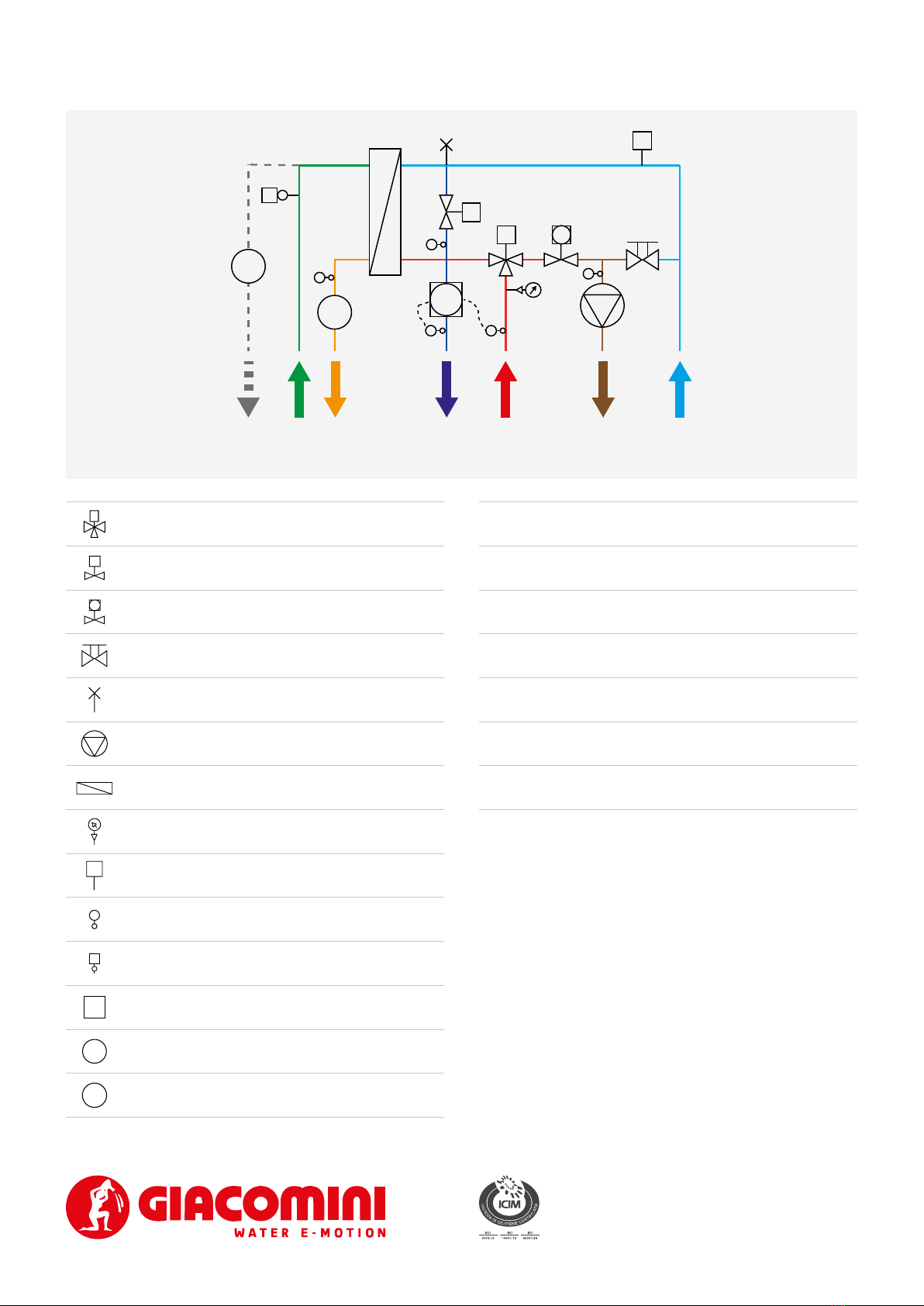
• G 3/4“F connections with adjustable tail pieces.
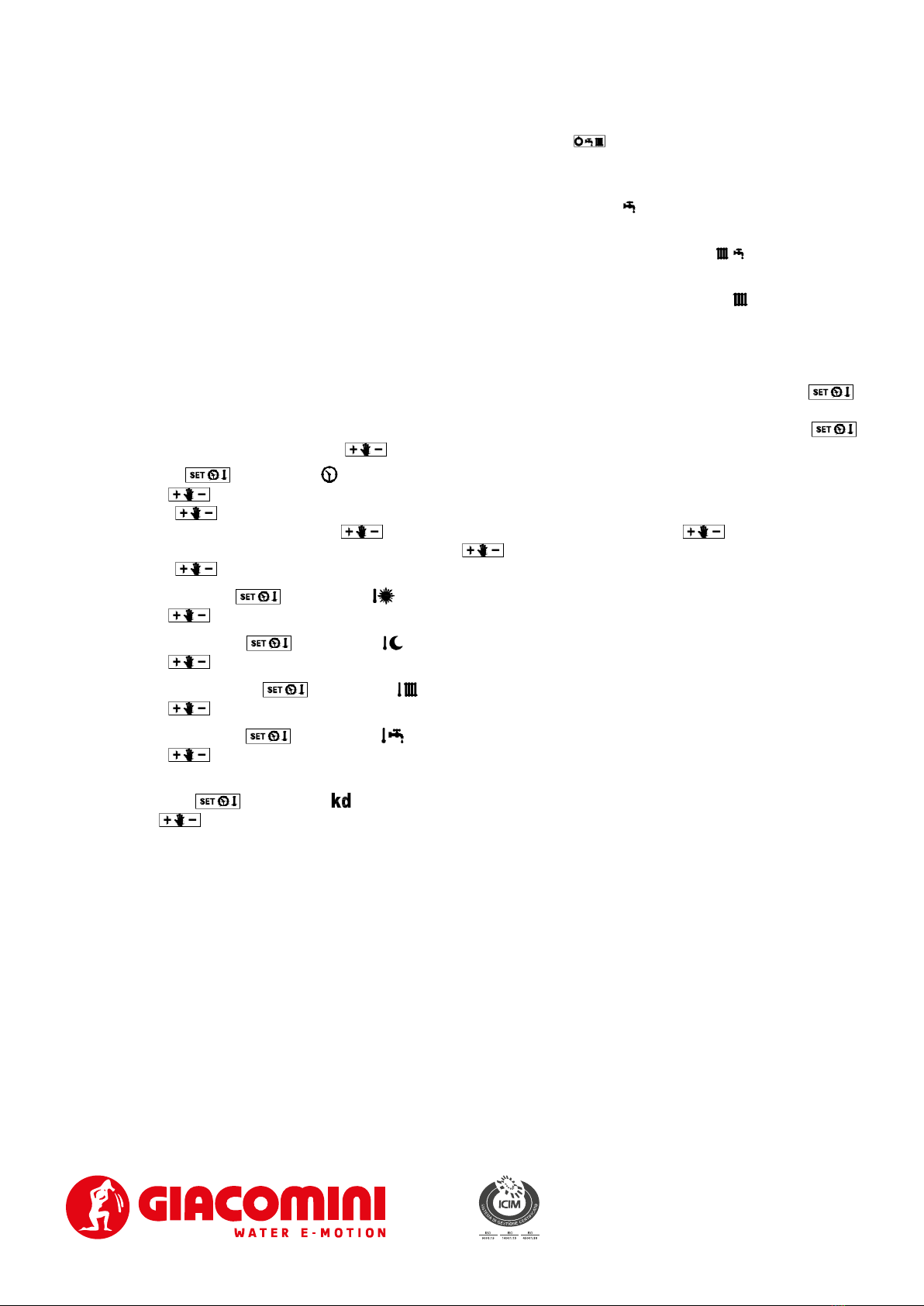
• Electronic thermoregulation with Set-point, to manage the DHW temperature and heating temperature.
• Remote control with chronothermostat function to manage the parameter (for single zone), with display.
• Multizone additional control by the free contact on the electronic board (additional thermostats to be ordered separately).
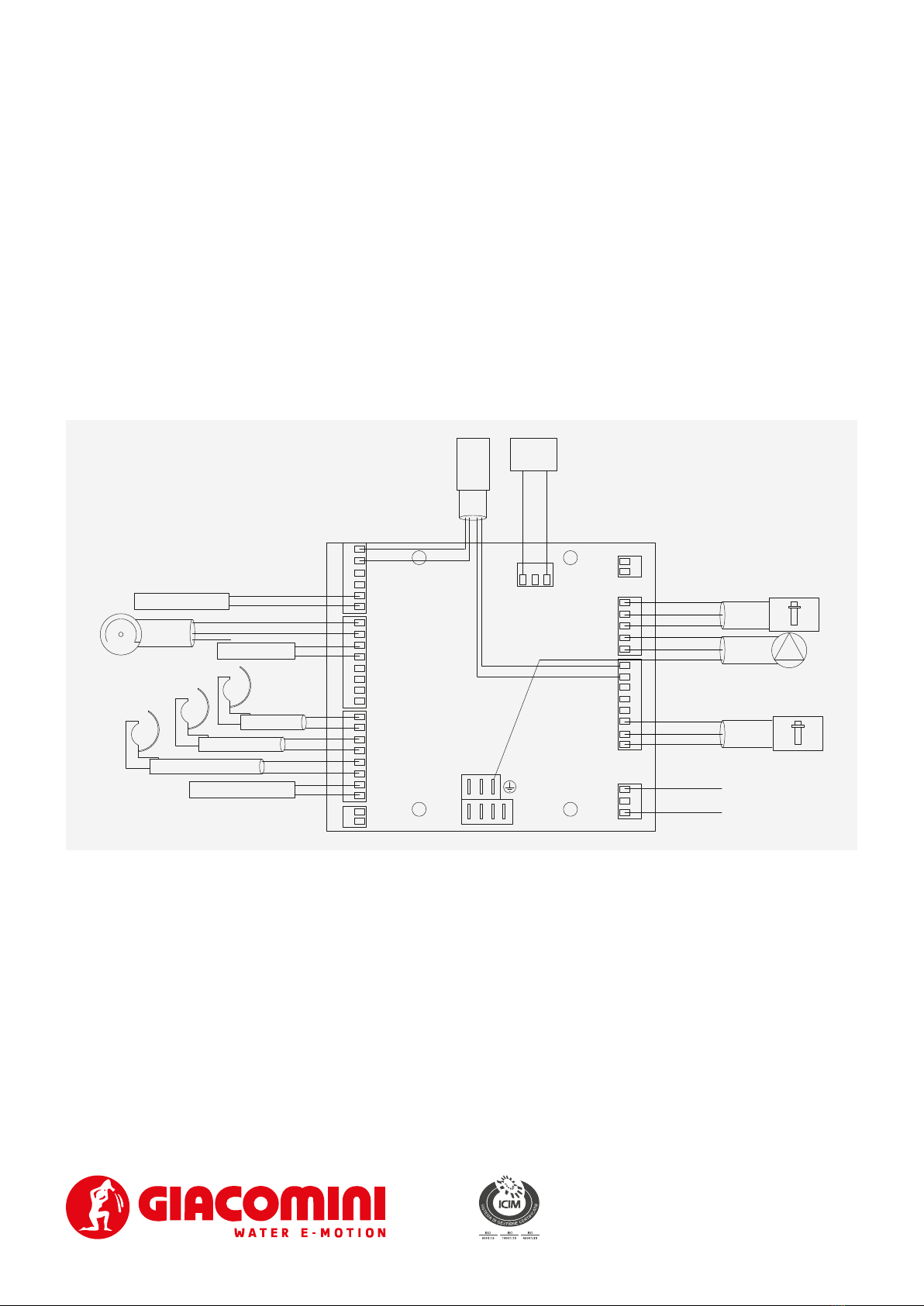
• External temperature probe for climatic compensation.
• Heat exchanger for instantaneous production of domestic hot water.
• Flow switch for priority of domestic hot water production.
• Motorizable 2-way zone valve, for thermal and electrical safety on the heating circuit.
• Motorized 3-way priority valve on the delivery of the primary circuit.
• Motorized 2-way modulating valve on the return of the primary circuit.
• Filter and manual air vent valve on the primary circuit.
• Safety pressure switch for low pressure on the primary circuit.
• Self-modulating circulator 15/6, centre distance 130 mm, complying with ErP directive (2009/125/CE).
• Heat exchanger and fully insulated piping.
• WRAS certied components for the domestic water circuit.
• Painted sheet metal cabinet (RAL9010), with key locking.
Caratteristiche principali
Versions and product codes
Completion codes
• GE552: thermal energy meter
• GE552-2: domestic water meters
• GE550Y010: optional additional unit output for domestic cold water outlet
• GE551Y133: template with shut-o valves and 3/4”M system connections
• GE551Y134: raised template with shut-o valves and 3/4”M system connections
• GE500Y258: additional shut-o valve to be installed on the template when present the GE550Y010 unit output
• R473M: thermo-electro actuator for 2-way zone valve for thermal safety on the heating circuit
• Data centralization components via M-Bus, GE552-4 series, or via Wireless M-Bus, GE552-W series
PRODUCT CODE HIU TYPE HEATING CIRCUIT
POWER
DHW HEAT EXCHANGER
NOMINAL POWER TEMPLATE WITH VALVES
GE556Y403 Heating and DHW production 26 kW 58 kW GE551Y133/GE551Y134
GE556Y406 Heating and DHW production 26 kW 67 kW GE551Y133/GE551Y134
NOTE. Remote control and external temperature probe included with HIU
NOTE. Use energy meters approved in accordance with the standardized “ow disturbance elements” and provided for by the EN 1434 for null rectilinear section
upstream and downstream of the meter, such as the GE552Y122.

3
Giacomini S.p.A.
Via per Alzo 39, 28017 San Maurizio d’Opaglio (NO) Italia
consulenza.prodotti@giacomini.com
+39 0322 923372 - giacomini.com
Components
PRIMARY CIRCUIT
1Housing for energy meter temperature probe
2Filter
3Motorized 3-way priority valve, for DHW function
4Pressure gauge 25 bar
5Heat exchanger for the domestic hot water function
6Manual air vent valve
7Minimum pressure switch
8Motorized two-way modulating valve
9Brass spacer for thermal energy meters
DHW PRO-
DUCTION
10 Flow switch
11 Brass spacer for water meters
HEATING
12 2-way zone valve for thermal and electrical safety
(motorizable with optional R473M thermo-electric actuator)
13 By-pass lockshield
14 Circulator
OTHER COMPONENTS
15 Cabinet with electronic regulation unit
16 Remote control / chronothermostat with display
17 External temperature probe
HYDRAULIC CONNECTIONS
ADomestic cold water inlet
BDomestic cold water outlet (optional)
CDomestic hot water outlet
DPrimary inlet
EPrimary outlet
FHeating return
GHeating delivery
BADEFGC
1
2
4
3
5
10
11
6
7
15
12
13
14
9
8
16 17

4
Giacomini S.p.A.
Via per Alzo 39, 28017 San Maurizio d’Opaglio (NO) Italia
consulenza.prodotti@giacomini.com
+39 0322 923372 - giacomini.com
Completion codes
• GE552: thermal energy meter. The meter temperature probe must be installed in the special housing (Components - Ref. 1).
• GE552-2: domestic water meters
• GE550Y010: optional additional unit output for domestic cold water outlet
• GE551Y133: template with shut-o valves and 3/4”M system connections
• GE551Y134: raised template with shut-o valves and 3/4”M system connections
• GE500Y258: additional shut-o valve to be installed on the template when present the GE550Y010 unit output
• R473M: thermo-electro actuator for 2-way zone valve for thermal safety on the heating circuit
B A DEFGC
GE550Y010
GE500Y258
GE552-2 GE552
R473M GE551Y133
GE551Y134

5
Giacomini S.p.A.
Via per Alzo 39, 28017 San Maurizio d’Opaglio (NO) Italia
consulenza.prodotti@giacomini.com
+39 0322 923372 - giacomini.com
Operation
Motorized 3-way priority valve
Motorized 2-way modulating valve
Motorizable 2-way zone valve
By-pass lockshield
Manual air vent valve
Circulator
Heat exchanger
Pressure gauge
PPMinimum pressure switch
Temperature probe
FFlow switch
EEBrass spacer for thermal energy meter
HBrass spacer for domestic hot water
CBrass spacer for domestic cold water
ADomestic cold water inlet
BDomestic cold water outlet (optional)
CDomestic hot water outlet
DPrimary inlet
EPrimary outlet
FHeating return
GHeating delivery
F
P
E
H
BADEFGC
C

6
Giacomini S.p.A.
Via per Alzo 39, 28017 San Maurizio d’Opaglio (NO) Italia
consulenza.prodotti@giacomini.com
+39 0322 923372 - giacomini.com
Secondary circuit: heating
Delivery (G) and return (F). The heating circuit is composed
of a motorized 2-way zone valve with thermal safety
function (the valve stops the ow in the system in the event
the delivery temperature exceeds 5 °C, the temperature
set on the remote control - Set Point), an adjustable by-
pass lockshield and a high-eciency circulator (ErP
2009/125/EC).
DEFG
Primary circuit
Inlet (D) and return (E). The primary circuit is composed of a
Y-lter, a motorized 3-way priority valve, a manual air vent
valve, a heat exchanger, a manometer, a minimum pressure
switch and a motorized 2-way modulating valve.
Energy Saving function: the 2-way modulating valve
controlled by the electronic management of the HIU,
restricts the ow demand from the primary to the minimum
necessary to obtain the preset Set-Point temperature.
The priority valve diverts the ow in the heat exchanger (if
there is a request of DHW: DHW ow switch enabled) or in
the heating system.
The thermal energy meter can be installed in place of the
brass spacer, tting its temperature probe in the relative
housing (Components - Ref. 1).
DE
Secondary circuit: DHW
Cold water inlet (A), hot water outlet (C) and cold water
outlet (B - optional). The DHW circuit is comprised of a ow
switch and a brass spacer for the introduction of the water
meter. A hot water meter can be installed Instead of the
brass spacer.
B A C

7
Giacomini S.p.A.
Via per Alzo 39, 28017 San Maurizio d’Opaglio (NO) Italia
consulenza.prodotti@giacomini.com
+39 0322 923372 - giacomini.com
Settings of the remote control/chronothermostat
Impostazione orologio e temperature
Depending on the operating mode selected (OFF / SUMMER / WINTER / HEATING ONLY) by pressing the button ,
the clock and the temperature of the boiler can be set.
The value is displayed for a time equal to the display settings time delay and is identied by its ashing icon. Press key
to pass to the next value and turn the knob to modify the value.
• Clock: press key until the icon and the time value start to ash.
Turn the knob to select the desired time.
Press the knob to pass to the minutes.
The minutes start ashing: turn the knob to select the desired minutes. Press the knob to pass to the day of
the week. The days of the week start ashing: turn the knob to select the desired day.
Press the knob to conrm the value entered.
• Day Set point: press key until the icon and the day set point value start to ash.
Turn the knob to select the desired value.
• Night Set point: press key until the icon and the night set point value start to ash.
Turn the knob to select the desired value.
• Heating Set point: press key until the icon and the heating set point value start to ash.
Turn the knob to select the desired value.
• DHW Set point: press key until the icon and the DHW set point value start to ash.
Turn the knob to select the desired value.
• Kd: this setting is only available if the remote control is congured as the modulator with the use of the external probe (P04
= 2 or 3). Press key until the icon and the relative value start to ash.
Turn the knob to select the desired value.
NOTE. For the other operating modes of the remote control, refer to the corresponding instruction sheet.
Operation in mode: OFF, SUMMER, WINTER, HEATING ONLY
The selection of the operating mode is done by repeatedly pressing the button .
•O:“OFF” and the current time are shown on the display. Only the antifreeze function (if set) is enabled in this mode.
Any request for the DHW or heating mode operation is ignored.
• Summer: the measured room temperature, the current time and the icon are displayed . The DHW, if set, and the antifreeze
function are enabled in this mode. Any request for the heating mode operation is ignored.
• Winter: the display shows the measured room temperature, the time and the current day, the icons and the program
set for the current day. All DHW, heating and, if set, antifreeze functions are enabled in this mode.
• Heating only: the display shows the measured room temperature, the time and the current day, the icon and the program
set for the current day. All heating and, if set, antifreeze functions are enabled in this mode.
Any request for the DHW mode operation is ignored.

8
Giacomini S.p.A.
Via per Alzo 39, 28017 San Maurizio d’Opaglio (NO) Italia
consulenza.prodotti@giacomini.com
+39 0322 923372 - giacomini.com
Preheating Function
The preheating function has the purpose of keeping the domestic water heat exchanger hot so as to shorten the initial
adjustment time required to reach the setpoint temperature, thus providing greater comfort.
The function can be enabled/disabled by setting the t12 parameter via remote control.
When enabled, during the stand-by stage in SUMMER or WINTER mode, the function continuously monitors the domestic
water probe and when the corresponding temperature falls below the DHW setpoint dierential threshold of -8 °C, a domestic
water cycle is forced on with power supplied at 30% until the DHW temperature reaches the adjustment value of the function
corresponding to the DHW setpoint -2 °C. There is a time limit of 2 minutes for the function to reach this value.
If the DHW temperature fails to reach the setpoint threshold value after this time, the function is interrupted and inhibited for
a period of 30 minutes.
WARNING. When the DHW preheating function is enabled, plan to install a compensation device (e.g., expansion vessel/water hammer damper).
Screed Heating Function
The screed heating function facilitates the installation of low-temperature oor systems.
It is supported in the WINTER and HEAT ONLY operating modes.
The function is enabled/disabled by setting the t13 parameter via remote control.
Once activated, it forces a request for operation in heating mode at a setpoint established by the t14 parameter, for a xed
time interval of 72 hours.
Subsequently, a new setpoint will be forcibly set with the value dened by the t15 parameter, for a time interval corresponding
to the value established by the t16 parameter, expressed in days.
Remote control Function
NOTE. To enable parameter programming, please refer to the remote-control manual.
PARAMETER RANGE DESCRIPTION DEFAULT CONFIGURATION SETTINGS
t00 0/1 Heat exchanger conguration 0 0=single, 1=double
t01 0/1 Heating range 1 0=standard, 1=reduced
t02 0/1 dr. group conguration 0 0=combined, 1=domestic water only
t03 0/120 Mixing valve time 12 seconds
t04 0/30 KD for OTC 30
t05 0/1 Enabling of H2O pressure switch 1 0=enabled, 1=disabled
t06 0/240 CH anticycle timming 30 seconds
t07 0/1 OVT type DHW 0 0=xed, 1=correlated to the Setpoint
t08 0/1 OVT type CH 0 0=xed, 1=correlated to the Setpoint
t09 0/1 Enabling safety valve 1 Screed heating timing nal phase
t10 0/60 DHW rq probe conguration 0 0=contact, 1=fluxmeter
t11 0/1 Disabling TA remotely 0 Screed heating timing nal phase
t12 0/1 Enabling preheating 0 0=disabled, 1=enabled
t13 0/1 Enabling screed heating 0 0=disabled, 1=enabled
t14 25/34 Screed heating starting temperature 72 hours 25 °C
t15 35/45 Screed heating ending temperature 45 °C
t16 4/10 Screed heating timing nal phase 4 days

9
Giacomini S.p.A.
Via per Alzo 39, 28017 San Maurizio d’Opaglio (NO) Italia
consulenza.prodotti@giacomini.com
+39 0322 923372 - giacomini.com
Circulator features
Operation
Automatic operation with constant pressure (recommended).
Automatic operation with variable pressure.
Automatic operation for air purging
(lasting 10 minutes): the circulator increases and reduces the
speed to aggregate the air bubbles and aid their elimination via
the air vent valve (not included with the circulator).
LED - Errors
xed green Normal operation.
ashing green Automatic operation for air purging.
ashing green/red Temporary anomalous situation:
1) incorrect voltage.
2) incorrect uid/ambient temperature
ashing red Circulator idle (permanent error: the circulator must be manually
reset). It may be necessary to replace the circulator.
NO LED
No electricity supply:
1) circulator not powered: check the cable connection.
2) LED damaged: check whether the circulator is working.
3) electronics damaged: replace the circulator
Self-modulating circulator 15/6 (230 V)
p-costant
6
5
4
3
2
1
00 0,5 1 1,5 2 2,5 3 Q [m3/h]
Q [m3/h]
H [m H2O]
00 0,5 11,5 2 2,5 3
10
20
30
40
P1 [w]
1 m
0,5 m
2 m
4 m
3 m
5 m
max
Circulator characteristics

10
Giacomini S.p.A.
Via per Alzo 39, 28017 San Maurizio d’Opaglio (NO) Italia
consulenza.prodotti@giacomini.com
+39 0322 923372 - giacomini.com
Electrical connections
Electric technical data
• Electronic board power supply: 230 V
• Supply voltage frequency: 50÷60 Hz
• Room operating temperature: -20÷60 °C
• Room storage temperature: -20÷80 °C
• Humidity: max 90 % @ 40° C non-condensing
• Maximum absorption: 7 VA
• Maximum length of external probe cable: 30 m
• Maximum length of remote control cable: 30 m
WARNING. Work on electrical components must be carried out by qualied personnel. Make sure that the power supply is disconnected when making
connections.
M-Bus
To connect the M-Bus data transfer cable to the concentrator, refer to the datasheet of the thermal energy meter used.
Electronic board
• The HIU is powered electrically by connecting the 230 V mains supply to the three-pin terminal board M1 of the electronic board.
• The remote control /chronothermostat (K480Y002) is connected to terminals 23-24 of the electronic board.
• The external temperature probe (K365PY002) is connected to terminals 27-28 of the electronic board.
• The optional safety thermostat (K373/K373I), is connected to terminals 39-40 of the electronic board.
• Multizone additional control to terminals 21-22 on the electronic board (additional thermostats to be ordered separately).
24 23 22 21 20 19
32 31 30 29 28 27 26 25
40 39 38 37 36 35 34 33
42 41
1 2 3 4 5 6 7 8
9 10 11 12 13
14 15
L N
18
17
16
CHIUDE - MARRONE
COMUNE - BLU
APRE - NERO
TENSIONE 230 Vac
CHIUDE - MARRONE
COMUNE - BLU
APRE - NERO
LINEA - MARRONE
NEUTRO - BLU
TERRA - GIALLO
ROSSO
BIANCO
VERDE
GRIGIO
NERO
LINEA - MARRONE
NEUTRO - BLU
FLUSSOSTATO
TESTA
R473M
230 VAC
PRESSOSTATO
SONDA SANITARIO
SONDA MANDATA
MISCELATRICE
CIRCOLATORE
DEVIATRICE
SONDA RITORNO
COMANDO REMOTO K480Y002
SONDA ESTERNA K365P
TERMOSTATO DI SICUREZZA K373

11
Giacomini S.p.A.
Via per Alzo 39, 28017 San Maurizio d’Opaglio (NO) Italia
consulenza.prodotti@giacomini.com
+39 0322 923372 - giacomini.com
Protection and safety systems
It is important that the HIUs are accessed only by skilled personnel authorised by the building administrator: the box is locked.
As optional is possible to install a K373/K373I safaty thermostat to prevent the high temperature on the heating circuit.
WARNING. Risk of burns and electric shock. The HIU must only be accessed by skilled personnel, authorised by the building administrator.
Installation, checks and maintenance
Heating circuit pressure
Periodically check the pressure value of heating circuit through the pressure gauge: it must be kept above 1 bar (pressure
values lower than 1 bar may damage the circulator by cavitation).
A pressure switch set on 0,8 bar is included to protect the circulator.
Provide a lling system for the heating circuit, that is a connection with a proper disconnector between the domestic water
and the heating circuits. Attention: Risk of burns.
WARNING. The HIU turns off automatically and the remote display shows the error E71 when the pressure is lower than 0,8 bar.
Fill up the system to turn the HIU back on.
WARNING. Risk of burns and electric shocks.
Installation must be carried out by qualied operators authorized by the building manager.
Refer to specic standards for use (installation, xing, etc...), operation, recalibration and replacement of meters.
Also refer to the assembly instructions provided with each meter.
IMPORTANT WARNING. Vibrations during transport may loosen the connections. Check all at-seat connections before start up and tighten if
necessary.
WARNING. Flush all pipes before installing the HIU on the template.
WARNING. Unused connections and ball valves must be closed with a cap.
WARNING. Upon installation, also include a lling circuit for the secondary system.
Wall mounting of template
Mount the template on the wall using screw anchors t for the type of wall and weight of the equipment, leaving a distance
of at least 1000 mm between the template base and the ceiling.
The HIU can be installed at any height on the wall, however we recommend leaving a 1500 mm min. distance between the
oor and the HIU cover base. Install the ball valves in the template holes and t them with the special washers using a wrench.
Connect the system pipes to the template hydraulic connections.
Refer to the template label for proper installation of the pipes.
Installation of the HIU on template
For an easier installation, the HIU includes 3/4”F at seat nuts with adjustable tail pieces (10 mm extension).
Before tting the HIU on the template, extend every single adjustable tail piece up to its max. length.
Using a hard surface as reference, press all the adjustable tail pieces (previously extended to their max. length) at the same
time to align them.
For installation with the GE551Y134 template, use the tie-rods on the template.
For installation with the GE551Y133 template, the user must measure the distance between the at seat of the tail pieces
and the tting slots of the HIU and mark it on the wall, considering the position of the template ball valve at seat and the
thickness of the gasket.
Drill the wall in the positions previously measured.
Use screw anchors t for the type of wall and weight of the equipment.
First insert the gaskets on the template and tighten gently by hand.
Complete the installation by tightening the HIU nuts on the template connections (max. torque 60 Nm) using a backup
spanner.

12
Giacomini S.p.A.
Via per Alzo 39, 28017 San Maurizio d’Opaglio (NO) Italia
consulenza.prodotti@giacomini.com
+39 0322 923372 - giacomini.com
GE556Y403 operating data
Primary circuit
Primary circuit for DHW production, modulating valve fully open
1,00
0,10
0,010,1 1,0 10,0
Q [m3/h]
∆p [bar]
Kv = 2,08
Primary circuit for heating, modulating valve and lockshield fully open
1,00
0,10
0,010,1 1,0 10,0
Q [m3/h]
∆p [bar]
Kv = 1,9
Secondary circuit for heating
LOW TEMPERATURE
HEATING (Δt35-30 °C)
PRIMARY CIRCUIT
WORKING CONDITIONS
CIRCULATOR
SPEED
FLOW RATE
[l/h]
POWER
[kW]
T INLET
[°C]
FLOW RATE
[l/h]
T OUTLET
[°C]
MAX. 1500 8,8
75 170 30
70 190 30
65 215 30
60 250 30
LOW TEMPERATURE
HEATING (Δt45-40 °C)
PRIMARY CIRCUIT
WORKING CONDITIONS
CIRCULATOR
SPEED
FLOW RATE
[l/h]
POWER
[kW]
T INLET
[°C]
FLOW RATE
[l/h]
T OUTLET
[°C]
MAX. 1500 8,8
75 215 40
70 250 40
65 300 40
60 375 40
HIGH TEMPERATURE
HEATING (Δt60-45 °C)
PRIMARY CIRCUIT
WORKING CONDITIONS
CIRCULATOR
SPEED
FLOW RATE
[l/h]
POWER
[kW]
T INLET
[°C]
FLOW RATE
[l/h]
T OUTLET
[°C]
MAX. 1500 26,3
75 750 45
70 900 45
65 1130 45
MAX. 1200 21 60 1200 45
HIGH TEMPERATURE
HEATING (Δt70-55 °C)
PRIMARY CIRCUIT
WORKING CONDITIONS
CIRCULATOR
SPEED
FLOW RATE
[l/h]
POWER
[kW]
T INLET
[°C]
FLOW RATE
[l/h]
T OUTLET
[°C]
MAX. 1200 21
75 900 55
70 1200 55
Diagram of the heating circulator - Circulator at constant ∆p
0
0 200 400 600 800 1000 1200 1400 1600
1
2
3
4
5
6
7
∆p [m H
2
O]
Q [l/h]

13
Giacomini S.p.A.
Via per Alzo 39, 28017 San Maurizio d’Opaglio (NO) Italia
consulenza.prodotti@giacomini.com
+39 0322 923372 - giacomini.com
Secondary circuit for DHW production
DHW PRODUCTION (Δt10-50 °C) PRIMARY CIRCUIT
WORKING CONDITIONS
FLOW RATE
[l/min]
FLOW RATE
[l/h]
POWER
[kW]
T INLET
[°C]
FLOW RATE
[l/h]
T OUTLET
[°C]
12 720 33
75 495 24
70 550 24
65 665 27
60 850 30
15 900 42
75 630 25
70 720 26
65 850 28
60 1050 30
17 1020 47,5
75 730 26
70 830 27
65 1000 29
60 1200 30
20 1200 56
75 875 27
70 1000 28
65 1200 30
60 1450 31
22 1320 54
75 980 28
70 1100 28
24 1440 58,8
75 1070 28
70 1200 28
Hydraulic data for domestic water circuit
0,010,1 1,0 10,0
0,10
1,00
∆p [bar]
Q [m3/h]
Kv = 2,22

14
Giacomini S.p.A.
Via per Alzo 39, 28017 San Maurizio d’Opaglio (NO) Italia
consulenza.prodotti@giacomini.com
+39 0322 923372 - giacomini.com
GE556Y403 energy saving features
Reduced ow rates requests to the primary, in heating operation
60 65 70 75
Primary delivery temp. [°C]
600
700
800
900
1000
1100
1200
1300
Primary flow rate [l/h]
26 kW
∆T (60-45 °C)
Q=1500 l/h
21 kW
∆T (70-55 °C)
Q=1200 l/h
High temperature
60 65 70 75
Primary delivery temp. [°C]
100
150
200
250
300
350
400
450
500
550
Primary flow rate [l/h]
9 kW
∆T (35-30 °C)
Q=1500 l/h
9 kW
∆T (45-40 °C)
Q=1500 l/h
Low temperature
Low return temperatures of the primary in DHW operation
60 65 70 75
Primary delivery temp. [°C]
20
22
24
26
28
30
32
Primary return temp. [°C]
12 l/min
15 l/min
17 l/min
20 l/min
22-24 l/min

15
Giacomini S.p.A.
Via per Alzo 39, 28017 San Maurizio d’Opaglio (NO) Italia
consulenza.prodotti@giacomini.com
+39 0322 923372 - giacomini.com
GE556Y406 operating data
Primary circuit
Primary circuit for DHW production, modulating valve fully open
1,00
0,10
0,010,1 1,0 10,0
Q [m3/h]
∆p [bar]
Kv = 2,13
Primary circuit for heating, modulating valve and lockshield fully open
1,00
0,10
0,010,1 1,0 10,0
Q [m3/h]
∆p [bar]
Kv = 1,9
Secondary circuit for heating
LOW TEMPERATURE
HEATING (Δt35-30 °C)
PRIMARY CIRCUIT
WORKING CONDITIONS
CIRCULATOR
SPEED
FLOW RATE
[l/h]
POWER
[kW]
T INLET
[°C]
FLOW RATE
[l/h]
T OUTLET
[°C]
MAX. 1500 8,8
75 170 30
70 190 30
65 215 30
60 250 30
LOW TEMPERATURE
HEATING (Δt45-40 °C)
PRIMARY CIRCUIT
WORKING CONDITIONS
CIRCULATOR
SPEED
FLOW RATE
[l/h]
POWER
[kW]
T INLET
[°C]
FLOW RATE
[l/h]
T OUTLET
[°C]
MAX. 1500 8,8
75 215 40
70 250 40
65 300 40
60 375 40
HIGH TEMPERATURE
HEATING (Δt60-45 °C)
PRIMARY CIRCUIT
WORKING CONDITIONS
CIRCULATOR
SPEED
FLOW RATE
[l/h]
POWER
[kW]
T INLET
[°C]
FLOW RATE
[l/h]
T OUTLET
[°C]
MAX. 1500 26,3
75 750 45
70 900 45
65 1130 45
MAX. 1200 21 60 1200 45
HIGH TEMPERATURE
HEATING (Δt70-55 °C)
PRIMARY CIRCUIT
WORKING CONDITIONS
CIRCULATOR
SPEED
FLOW RATE
[l/h]
POWER
[kW]
T INLET
[°C]
FLOW RATE
[l/h]
T OUTLET
[°C]
MAX. 1200 21
75 900 55
70 1200 55
Diagram of the heating circulator - Circulator at constant ∆p
0
0 200 400 600 800 1000 1200 1400 1600
1
2
3
4
5
6
7
∆p [m H
2
O]
Q [l/h]

16
Giacomini S.p.A.
Via per Alzo 39, 28017 San Maurizio d’Opaglio (NO) Italia
consulenza.prodotti@giacomini.com
+39 0322 923372 - giacomini.com
Secondary circuit for DHW production
DHW PRODUCTION (Δt10-50 °C) PRIMARY CIRCUIT
WORKING CONDITIONS
FLOW RATE
[l/min]
FLOW RATE
[l/h]
POWER
[kW]
T INLET
[°C]
FLOW RATE
[l/h]
T OUTLET
[°C]
12 720 33,5
75 510 18,5
70 580 20
65 670 22
15 900 42
75 660 20,5
70 750 22
65 880 24
17 1020 47,5
75 770 22
70 880 23,5
65 1020 25
20 1200 56
75 940 23,5
70 1050 24,2
22 1320 61,5
75 1040 24
70 1160 24,6
24 1440 67
75 1150 25
70 1280 25
Hydraulic data for domestic water circuit
0,010,1 1,0 10,0
0,10
1,00
∆p [bar]
Q [m3/h]
Kv = 2,32

17
Giacomini S.p.A.
Via per Alzo 39, 28017 San Maurizio d’Opaglio (NO) Italia
consulenza.prodotti@giacomini.com
+39 0322 923372 - giacomini.com
GE556Y406 energy saving features
Low return temperatures of the primary in DHW operation
65 70 75
Primary delivery T. [°C]
15
17
19
21
23
25
27
Primary return T. [°C]
12 l/min
15 l/min
17 l/min
20 l/min
22 l/min
24 l/min
Reduced ow rates requests to the primary, in heating operation
60 65 70 75
Primary delivery temp. [°C]
600
700
800
900
1000
1100
1200
1300
Primary flow rate [l/h]
26 kW
∆T (60-45 °C)
Q=1500 l/h
21 kW
∆T (70-55 °C)
Q=1200 l/h
High temperature
60 65 70 75
Primary delivery temp. [°C]
100
150
200
250
300
350
400
450
500
550
Primary flow rate [l/h]
9 kW
∆T (35-30 °C)
Q=1500 l/h
9 kW
∆T (45-40 °C)
Q=1500 l/h
Low temperature

18
Giacomini S.p.A.
Via per Alzo 39, 28017 San Maurizio d’Opaglio (NO) Italia
consulenza.prodotti@giacomini.com
+39 0322 923372 - giacomini.com
Dimensions
ADomestic cold water inlet
BDomestic cold water outlet (optional)
CDomestic hot water outlet
DPrimary inlet
EPrimary outlet
FHeating return
GHeating delivery
XFairleads
Dimensions in mm
HIU + GE551Y133 TEMPLATE
450
5060
180
768
60 60 60 60 6040
180
X
EDGF
CAB
HIU + GE551Y134 TEMPLATE
450
5060
180
768
60 60 60 60 6040
180
X
EDG
F
CA
B
HIU ONLY
450
5060
180
700
60 60 60 60 6040
180
X
EDGF
CAB
450
5060
180
700
60 60 60 60 6040
180
X
EDGF
CAB

19
Giacomini S.p.A.
Via per Alzo 39, 28017 San Maurizio d’Opaglio (NO) Italia
consulenza.prodotti@giacomini.com
+39 0322 923372 - giacomini.com
WRAScertication
REF. IN “COMPONENTS” PARAGRAPH COMPONENT CERTIFICATE NUMBER
-Gaskets 1509514
10 Flow switch 2111302
5Heat exchanger 1909083
Reference Standards
• UNI EN 1434
• EN 60751
• EN 61107
• Measuring Instruments Directive 2014/32/UE (MID)
• ErP Directive 2009/125/CE

20
Giacomini S.p.A.
Via per Alzo 39, 28017 San Maurizio d’Opaglio (NO) Italia
consulenza.prodotti@giacomini.com
+39 0322 923372 - giacomini.com
IT AVVERTENZE PER IL CORRETTO SMALTIMENTO DEL PRODOTTO
Questo prodotto rientra nel campo di applicazione della Direttiva 2012/19/UE riguardante la gestione dei riuti di apparecchiature elettriche ed elettroniche (RAEE).
L’apparecchio non deve essere eliminato con gli scarti domestici in quanto composto da diversi materiali che possono essere riciclati presso le strutture adeguate.
Informarsi attraverso l’autorità comunale per quanto riguarda l’ubicazione delle piattaforme ecologiche atte a ricevere il prodotto per lo smaltimento ed il suo successivo corretto riciclaggio.
Si ricorda, inoltre, che a fronte di acquisto di apparecchio equivalente, il distributore è tenuto al ritiro gratuito del prodotto da smaltire.
Il prodotto non è potenzialmente pericoloso per la salute umana e l’ambiente, ma se abbandonato nell’ambiente impatta negativamente sull’ecosistema.
Leggere attentamente le istruzioni prima di utilizzare l’apparecchio per la prima volta. Si raccomanda di non usare assolutamente il prodotto per un uso diverso da quello a cui è stato destinato, essendoci
pericolo di shock elettrico se usato impropriamente.
Il simbolo del bidone barrato, presente sull’etichetta posta sull’apparecchio, indica la rispondenza di tale prodotto alla normativa relativa ai riuti di apparecchiature elettriche ed elettroniche.
L’abbandono nell’ambiente dell’apparecchiatura o lo smaltimento abusivo della stessa sono puniti dalla legge.
EN IMPORTANT INFORMATION FOR CORRECT DISPOSAL OF THE PRODUCT
This product falls into the scope of the Directive 2012/19/EU concerning the management of Waste Electrical and Electronic Equipment (WEEE).
This product shall not be dispose in to the domestic waste as it is made of different materials that have to be recycled at the appropriate facilities.
Inquire through the municipal authority regarding the location of the ecological platforms to receive the product for disposal and its subsequent correct recycling.
Furthermore, upon purchase of an equivalent appliance, the distributor is obliged to collect the product for disposal free of charge.
The product is not potentially dangerous for human health and the environment, but if abandoned in the environment can have negative impact on the environment. Read carefully the instructions before
using the product for the rst time. It is recommended that you do not use the product for any purpose rather than those for which it was intended, there being a danger of electric shock if used improperly.
The crossed-out wheeled dustbin symbol, on the label on the product, indicates the compliance of this product with the regulations regarding Waste Electrical and Electronic Equipment.
Abandonment in the environment or illegal disposal of the product is punishable by law.
FR AVERTISSEMENTS POUR L’ÉLIMINATION CORRECTE DU PRODUIT
Ce produit entre dans le champ d’application de la directive 2012/19 / UE relative à la gestion des déchets équipements électriques et électroniques (DEEE).
L’appareil ne doit pas être jeté avec les ordures ménagères car il est fait de différents matériaux pouvant être recyclés dans des centres appropriés.
Renseignez-vous auprès de l’autorité locale concernant l’emplacement des plates-formes écologiques appropriées pour recevoir le produit pour sa destruction et son recyclage correct ultérieur.
Il convient également de rappeler que, en cas d’achat d’un appareil équivalent, le distributeur est tenu de collecter le produit à détruire. Le produit n’est potentiellement pas dangereux pour la santé humaine
et l’environnement, mais s’il est abandonné dans l’environnement, il a un impact négatif sur l’écosystème.
Lisez attentivement les instructions avant d’utiliser l’appareil pour la première fois.
Il est interdit d’utiliser le produit pour un usage différent de celui auquel il était destiné, il y a risque de choc électrique si utilisé incorrectement.
Le symbole de la poubelle barrée sur l’étiquette de l’appareil indique sa correspondance produit à la législation relative aux déchets d’équipements électriques et électroniques.
L’abandon dans l’environnement de l’équipement ou l’élimination illégale de l’équipement est punissable par la loi.
DE WICHTIGE HINWEISE ZUR KORREKTEN ENTSORGUNG DES PRODUKTS
Dieses Produkt fällt in den Anwendungsbereich der Richtlinie 2012/19/EU über die Entsorgung von Elektro- und Elektronik - Altgeräten (WEEE).
Dieses Produkt darf nicht in den Hausmüll entsorgt werden, da es aus verschiedenen Materialien besteht, die in entsprechenden Einrichtungen recycelt werden müssen.
Erkundigen sie sich bei ihrer Gemeinde nach dem Standort des nächsten Recyclinghofs bzw. der nächsten Annahmestelle, um das Produkt dem Recycling zuzuführen bzw. fachgerecht zu entsorgen.
Darüber hinaus ist der Händler verpichtet, das Produkt beim Kauf eines gleichwertigen Geräts kostenlos zu entsorgen. Das Produkt ist für die menschliche Gesundheit und die Umwelt potenziell
nicht gefährlich. Diese können sich aber, falls sie in der Umwelt gelangen, negativ auf diese auswirken. Lesen Sie daher vor dem ersten Gebrauch des Produkts die Inbetriebnahme-, Bedienungs- und
Entsorgungsanweisungen sorgfältig durch. Es wird empfohlen, dass Sie das Produkt nur für den vorgesehenen Zweck verwenden.
Bei unsachgemäßer Verwendung bzw. Fehlgebrauch besteht die Gefahr eines elektrischen Schlags.
Das Symbol der durchgestrichenen Mülltonne auf dem Etikett des Produkts weist auf die Konformität dieses Produkts zu den Vorschriften für Elektro- und Elektronik-Altgeräte hin. Das Ablagern
in der Umwelt oder die illegale Entsorgung des Produkts ist strafbar.
Package Disposal. Carton boxes: paper recycling. Plastic bags and bubble wrap: plastic
recycling.
Product Disposal. Do not dispose of product as municipal waste at the end of its life cycle.
Dispose of product at a special recycling platform managed by local authorities or at retailers
providing this type of service.
Safety Warning. Installation, commissioning and periodical maintenance of the product
must be carried out by qualied operators in compliance with national regulations and/or local
standards. A qualied installer must take all required measures, including use of Individual
Protection Devices, for his and others’ safety. An improper installation may damage people,
animals or objects towards which Giacomini S.p.A. may not be held liable.
Additional information. For more information, go to giacomini.com or contact our technical
assistance service. This document provides only general indications. Giacomini S.p.A. may change
at any time, without notice and for technical or commercial reasons, the items included herewith.
The information included in this technical sheet do not exempt the user from strictly complying
with the rules and good practice standards in force.
This manual suits for next models
1
Table of contents
Other Giacomini Industrial Equipment manuals

Giacomini
Giacomini R586SY001 User manual

Giacomini
Giacomini GE556-5 Operating instructions

Giacomini
Giacomini R553FPDB User manual

Giacomini
Giacomini R557RY045 User manual

Giacomini
Giacomini GE556-1 Series User manual

Giacomini
Giacomini KLIMAdomotic KPM45Y002 User manual

Giacomini
Giacomini K470WX021 User manual

Giacomini
Giacomini K470H Series User manual

Giacomini
Giacomini GE551Y194 User manual

Giacomini
Giacomini GE556Y171 User manual