6
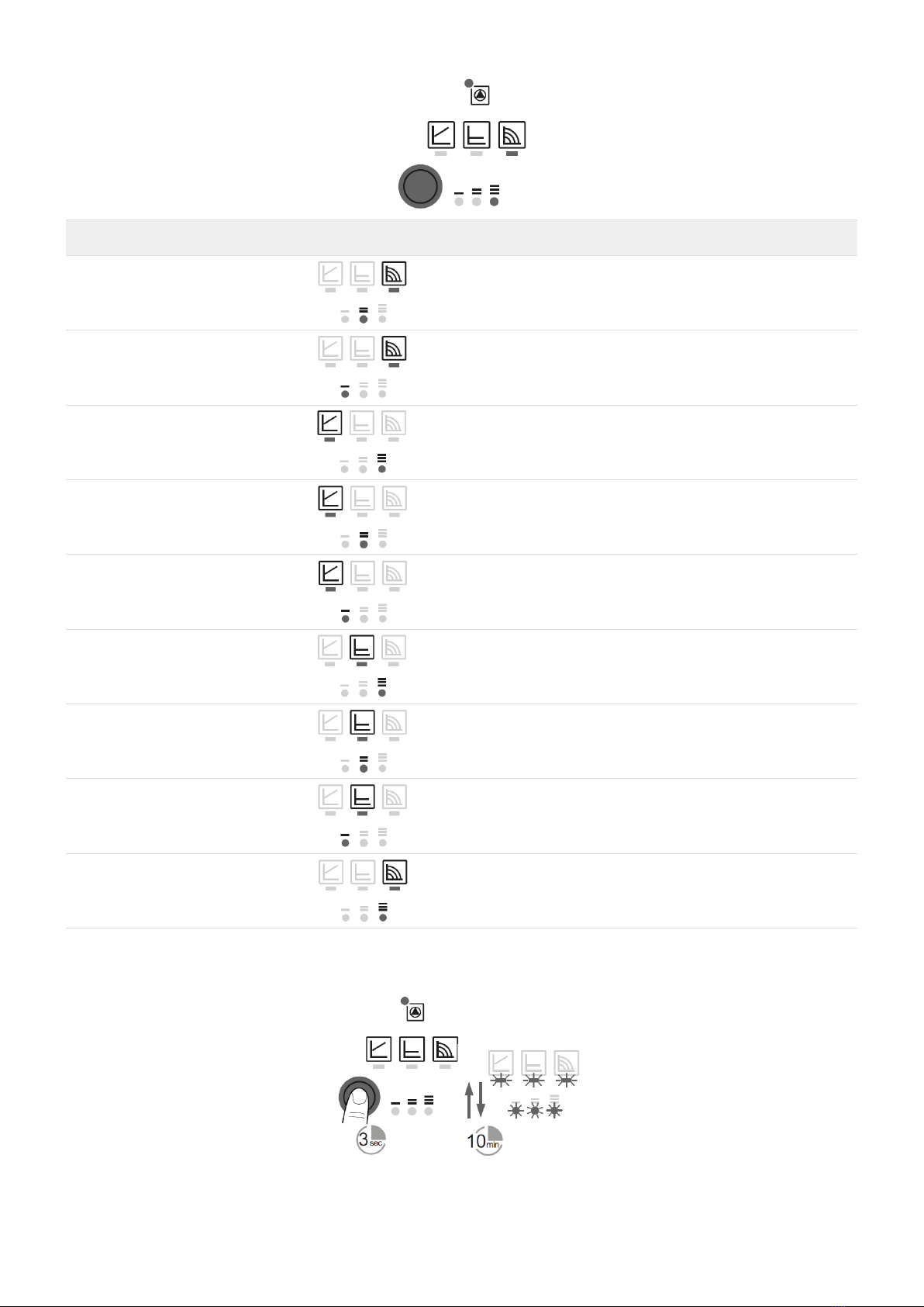
Działanie pompy Circulator operation
Zmienna różnica ciśnień Δp-v (I, II, III)
CZalecany dla dwururowych systemów grzewczych z grzejnikami w celu
zmniejszenia hałasu przepływu na zaworach termostatycznych. Pompa redukuje
poziom podnoszenia do połowy w przypadku spadku przepływu w sieci
rurociągów. Oszczędność energii elektrycznej dzięki dostosowaniu wysokości
podnoszenia do wymaganego przepływu objętościowego i niższych prędkości
przepływu. Istnieją trzy wstępnie zdeniowane krzywe pompy (I, II, III) do wyboru.
0
0
1
2
3
4
5
6
7
0
10
20
30
40
50
60
70
0,5 1,0 1,5 2,0 3,0 4,03,52,5
0 0,5 1,0 1,5 2,0 3,0 4,03,52,5
Q [m3/h]
H [m]
H [kPa]
III
II
I
∆p-v
max.
max.
III II I
0
0
1
2
0
20
40
60
3
4
5
6
7
8
∆p-c (costante)
0
10
20
30
40
50
60
70
80
0,5 1,0 1,5 2,0 3,0 4,03,52,5
0 0,5 1,0 1,5 2,0 3,0 4,03,52,5
Q [m3/h]
Q [m3/h]
P1 [W] H [m]
H [kPa]
III
II
I
∆p-c
max.
max.
III
II
I
0
0
2
0
20
40
60
4
6
8
10
Velocità costante (I, II, III)
0
10
20
30
40
50
60
70
80
0,5 1,0 1,5 2,0 3,0 4,03,52,5
0 0,5 1,0 1,5 2,0 3,0 4,03,52,5
Q [m3/h]
Q [m3/h]
P1 [W] H [m]
H [kPa]
III
II
I
III
II
I
0
20
40
60
3
4
5
6
7
8
∆p-v (variabile)
0
10
20
30
40
50
60
70
80
0,5 1,0 1,5 2,0 3,0 4,03,52,5
0 0,5 1,0 1,5 2,0 3,0 4,03,52,5
Q [m3/h]
P1 [W]
H [m]
H [kPa]
III
II
I
∆p-v
max.
max.
III II I
0
0
1
2
0
20
40
60
3
4
5
6
7
8
∆p-c (costante)
0
10
20
30
40
50
60
70
80
0,5 1,0 1,5 2,0 3,0 4,03,52,5
0 0,5 1,0 1,5 2,0 3,0 4,03,52,5
Q [m3/h]
Q [m3/h]
P1 [W] H [m]
H [kPa]
III
II
I
∆p-c
max.
max.
III
II
I
0
0
2
0
20
40
60
4
6
8
10
Velocità costante (I, II, III)
0
10
20
30
40
50
60
70
80
0,5 1,0 1,5 2,0 3,0 4,03,52,5
0 0,5 1,0 1,5 2,0 3,0 4,03,52,5
Q [m3/h]
Q [m3/h]
P1 [W] H [m]
H [kPa]
III
II
I
III
II
I
Variable dierential pressure Δp-v (I, II, III)
Recommended for two-pipe heating systems with radiators to reduce the ow
noise at thermostatic valves. The pump reduces the delivery head to half in the
case of decreasing volume ow in the pipe network.
Electrical energy saving by adjusting the delivery head to the volume ow
requirement and lower ow rates.
There are three pre-dened pump curves (I, II, III) to choose from.
Stała różnica ciśnień Δp-c (I, II, III)
Zalecany do ogrzewania podłogowego dla dużych rur lub wszystkich
zastosowań bez zmiennej krzywej sieci (np. pompy zbiornikowe), jak również
do jednorurowych systemów grzewczych z grzejnikami. Sterowanie utrzymuje
stałą wysokość podnoszenia niezależnie od pompowanego przepływu
objętościowego. Istnieją trzy wstępnie zdeniowane krzywe pompy (I, II, III), do
wyboru. (I, II, III).
0
0
1
2
0
20
40
60
3
4
5
6
7
8
∆p-v (variabile)
0
10
20
30
40
50
60
70
80
0,5 1,0 1,5 2,0 3,0 4,03,52,5
0 0,5 1,0 1,5 2,0 3,0 4,03,52,5
Q [m3/h]
Q [m3/h]
P1 [W] H [m]
H [kPa]
III
II
I
∆p-v
max.
max.
III II I
0
0
1
2
3
4
5
6
7
0
10
20
30
40
50
60
70
0,5 1,0 1,5 2,0 3,0 4,03,52,5
0 0,5 1,0 1,5 2,0 3,0 4,03,52,5
Q [m3/h]
Q [m3/h]
P1 [W] H [m]
H [kPa]
III
II
I
∆p-c
max.
max.
III
II
I
0
0
2
0
20
40
60
4
6
8
10
Velocità costante (I, II, III)
0
10
20
30
40
50
60
70
80
0,5 1,0 1,5 2,0 3,0 4,03,52,5
0 0,5 1,0 1,5 2,0 3,0 4,03,52,5
Q [m3/h]
Q [m3/h]
P1 [W] H [m]
H [kPa]
III
II
I
III
II
I
0
0
1
2
0
20
40
60
3
4
5
6
7
8
∆p-v (variabile)
0
10
20
30
40
50
60
70
80
0,5 1,0 1,5 2,0 3,0 4,03,52,5
0 0,5 1,0 1,5 2,0 3,0 4,03,52,5
Q [m3/h]
Q [m3/h]
P1 [W] H [m]
H [kPa]
III
II
I
∆p-v
max.
max.
III II I
0
0
1
2
0
20
40
60
3
4
5
6
7
8
∆p-c (costante)
0
10
20
30
40
50
60
70
80
0,5 1,0 1,5 2,0 3,0 4,03,52,5
0 0,5 1,0 1,5 2,0 3,0 4,03,52,5
Q [m3/h]
P1 [W] H [m]
H [kPa]
III
II
I
∆p-c
max.
max.
III
II
I
0
0
2
0
20
40
60
4
6
8
10
Velocità costante (I, II, III)
0
10
20
30
40
50
60
70
80
0,5 1,0 1,5 2,0 3,0 4,03,52,5
0 0,5 1,0 1,5 2,0 3,0 4,03,52,5
Q [m3/h]
Q [m3/h]
P1 [W] H [m]
H [kPa]
III
II
I
III
II
I
Constant dierential pressure Δp-c (I, II, III)
Recommended for underoor heating for large-sized pipes or all applications
without a variable pipe network curve (e.g. storage charge pumps), as well as
single-pipe heating systems with radiators.
The control keeps the set delivery head constant irrespective of the pumped
volume ow.
There are three pre-dened pump curves (I, II, III) to choose from.
Prędkość stała (I, II, III) [ustawienie fabryczne]
Zalecany do systemów o stałym oporze w instalacji.
Pompa pracuje z trzema zalecanymi stałymi stopniami prędkości obrotowej
(I, II, III).
0
0
1
2
0
20
40
60
3
4
5
6
7
8
∆p-v (variabile)
0
10
20
30
40
50
60
70
80
0,5 1,0 1,5 2,0 3,0 4,03,52,5
0 0,5 1,0 1,5 2,0 3,0 4,03,52,5
Q [m3/h]
Q [m3/h]
P1 [W] H [m]
H [kPa]
III
II
I
∆p-v
max.
max.
III II I
0
0
1
2
0
20
40
60
3
4
5
6
7
8
∆p-c (costante)
0
10
20
30
40
50
60
70
80
0,5 1,0 1,5 2,0 3,0 4,03,52,5
0 0,5 1,0 1,5 2,0 3,0 4,03,52,5
Q [m3/h]
Q [m3/h]
P1 [W] H [m]
H [kPa]
III
II
I
∆p-c
max.
max.
III
II
I
0
0
2
4
6
8
10
Velocità costante (I, II, III)
0
10
20
30
40
50
60
70
0,5 1,0 1,5 2,0 3,0 4,03,52,5
0 0,5 1,0 1,5 2,0 3,0 4,03,52,5
Q [m3/h]
H [kPa]
III
II
I
0
0
1
2
0
20
40
60
3
4
5
6
7
8
∆p-v (variabile)
0
10
20
30
40
50
60
70
80
0,5 1,0 1,5 2,0 3,0 4,03,52,5
0 0,5 1,0 1,5 2,0 3,0 4,03,52,5
Q [m3/h]
Q [m3/h]
P1 [W] H [m]
H [kPa]
III
II
I
∆p-v
max.
max.
III II I
0
0
1
2
0
20
40
60
3
4
5
6
7
8
∆p-c (costante)
0
10
20
30
40
50
60
70
80
0,5 1,0 1,5 2,0 3,0 4,03,52,5
0 0,5 1,0 1,5 2,0 3,0 4,03,52,5
Q [m3/h]
Q [m3/h]
P1 [W] H [m]
H [kPa]
III
II
I
∆p-c
max.
max.
III
II
I
0
0
2
0
20
40
60
4
6
8
10
Velocità costante (I, II, III)
0
10
20
30
40
50
60
70
80
0,5 1,0 1,5 2,0 3,0 4,03,52,5
0 0,5 1,0 1,5 2,0 3,0 4,03,52,5
Q [m3/h]
P1 [W] H [m]
H [kPa]
III
II
I
III
II
I
Constant speed (I, II, III) [FACTORY SETTING]
Recommended for systems with xed system resistance requiring a constant
volume ow.
The pump runs in three prescribed xed speed stages (I, II, III).