JETWAY NF632E Series User manual

NF632ESeries
UserManual
NO. G03-NF632E-F
Revision: 6.0
Release date:October12,2018
Trademark:
*Specifications and Information contained inthis documentation arefurnished forinformation use only,and are
subjecttochangeat anytimewithout notice,and shouldnot be construed asacommitmentbymanufacturer.

ii
Environmental Protection Announcement
Donotdisposethiselectronicdeviceintothe trashwhilediscarding.Tominimize
pollutionandensureenvironmentprotectionofmotherearth,pleaserecycle.

iii
ENVIRONMENTALSAFETYINSTRUCTION.......................................................................... iv
USER SNOTICE....................................................................................................................... v
MANUALREVISIONINFORMATION...................................................................................... v
ITEMCHECKLIST..................................................................................................................... v
CHAPTER 1 INTRODUCTION OF THEMOTHERBOARD
1-1FEATUREOF MOTHERBOARD............................................................................... 1
1-2SPECIFICATION......................................................................................................... 2
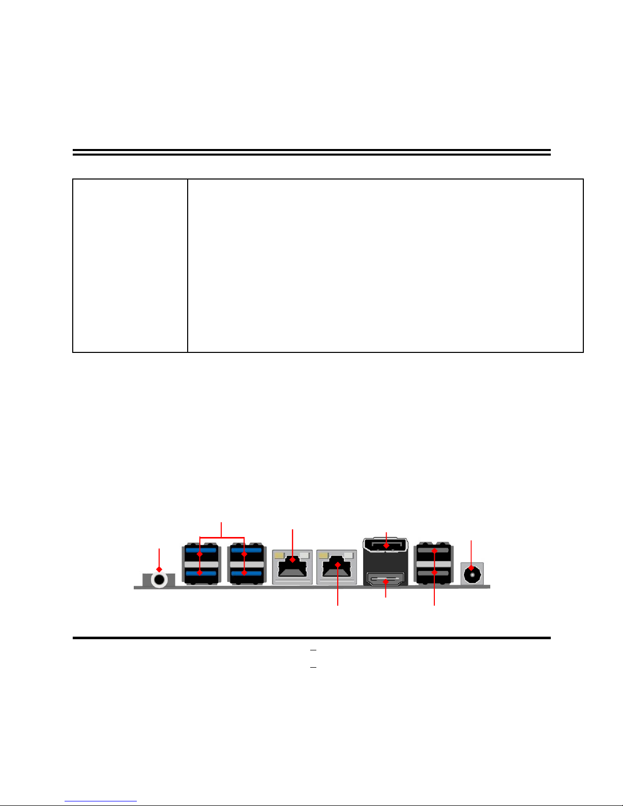
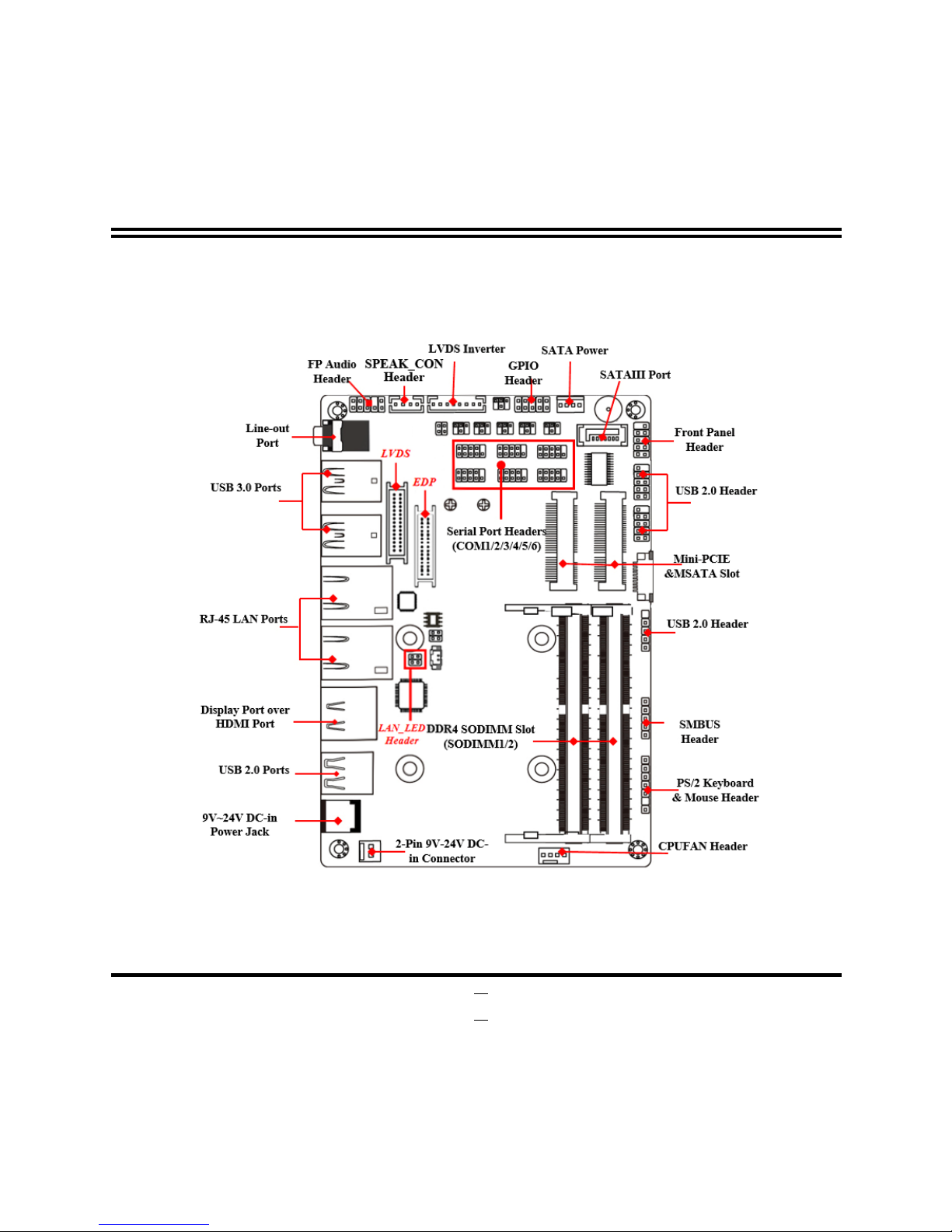
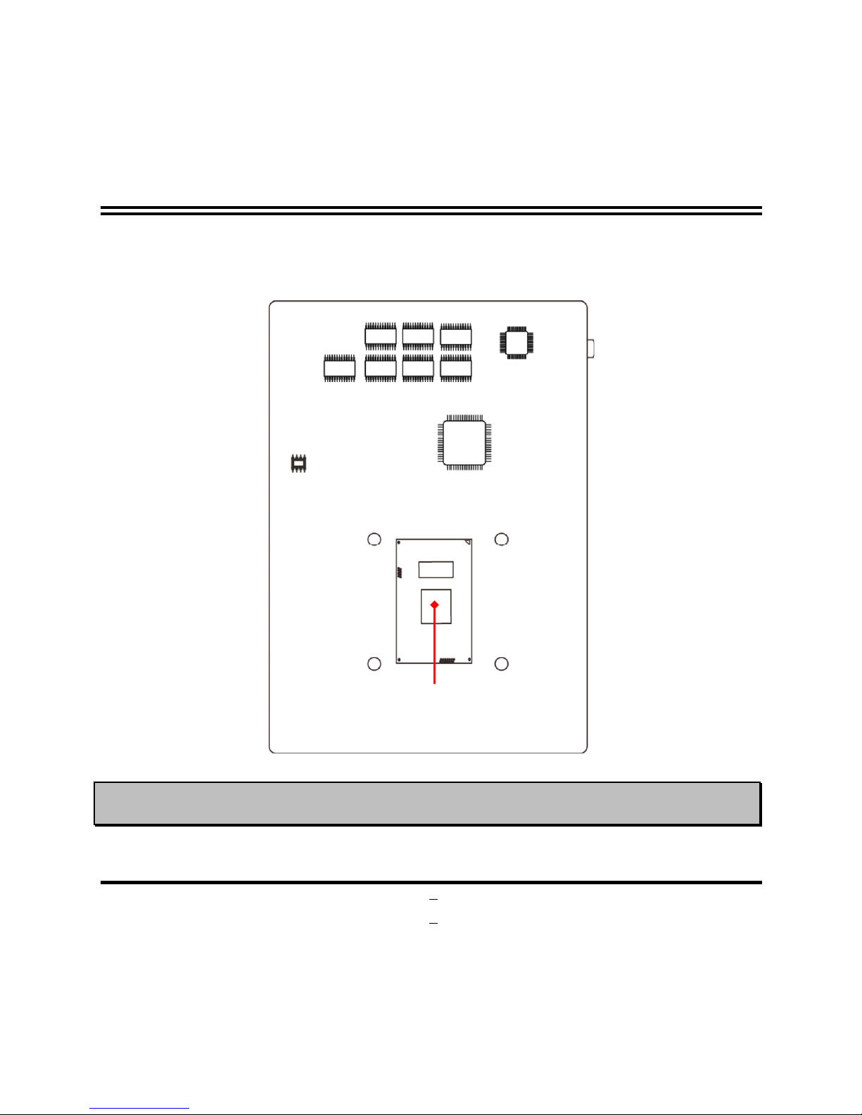
1-3LAYOUTDIAGRAM................................................................................................... 3
CHAPTER 2 HARDWAREINSTALLATION
2-1JUMPER SETTING..................................................................................................... 9
2-2CONNECTORSANDHEADERS............................................................................... 14
2-2-1CONNECTORS............................................................................................. 14
2-2-2HEADERS..................................................................................................... 17
CHAPTER 3 INTRODUCINGBIOS
3-1ENTERINGSETUP..................................................................................................... 25
3-2BIOSMENU SCREEN................................................................................................ 26
3-3FUNCTION KEYS....................................................................................................... 26
3-4GETTINGHELP.......................................................................................................... 27
3-5MEMU BARS.............................................................................................................. 27
3-6MAIN MENU................................................................................................................ 28
3-7ADVANCED MENU.................................................................................................... 29
3-8CHIPSETMENU......................................................................................................... 42
3-9SECURITYMENU....................................................................................................... 45
3-10BOOTMENU.............................................................................................................. 46
3-11SAVE& EXITMENU .................................................................................................. 47
TABLE OF CONTENT

iv
Environmental SafetyInstruction
lAvoidthe dusty,humidityand temperatureextremes.Donotplacethe productin
anyarea whereitmaybecomewet.
l0to40 centigrade isthesuitabletemperature.(The figurecomesfromthe request
ofthemainchipset)
lGenerallyspeaking,dramaticchangesintemperaturemaylead tocontact
malfunctionandcracklesdue toconstantthermalexpansionandcontractionfrom
the weldingspots thatconnectcomponentsandPCB.Computershouldgo
throughanadaptivephasebeforeitbootswhen itismovedfromacold
environmenttoawarmeronetoavoidcondensationphenomenon.Thesewater
dropsattached onPCBorthe surfaceofthe componentscan bringabout
phenomenaasminorascomputerinstabilityresultedfromcorrosionand oxidation
fromcomponentsandPCBorasmajorasshortcircuitthatcan burnthe
components.Suggeststartingthe computeruntil thetemperaturegoesup.
lTheincreasingtemperatureofthecapacitormaydecreasethelifeofcomputer.
Usingthe closecasemaydecreasethelifeofotherdevicebecausethehigher
temperatureintheinnerofthe case.
lAttention totheheatsinkwhen you over-clocking.The highertemperaturemay
decreasethelifeofthedeviceandburnedthecapacitor.

v
USER SNOTICE
COPYRIGHTOFTHIS MANUALBELONGSTOTHE MANUFACTURER. NOPARTOFTHISMANUAL,
INCLUDINGTHE PRODUCTSAND SOFTWARE DESCRIBED IN ITMAYBEREPRODUCED, TRANSMITTED
ORTRANSLATED INTOANY LANGUAGEIN ANYFORMORBY ANY MEANSWITHOUTWRITTEN
PERMISSION OFTHE MANUFACTURER.
THIS MANUALCONTAINS ALL INFORMATIONREQUIREDTOUSE THIS MOTHER-BOARD SERIESANDWE
DOASSURE THISMANUALMEETSUSER SREQUIREMENTBUTWILL CHANGE,CORRECTANY TIME
WITHOUTNOTICE.MANUFACTURER PROVIDES THIS MANUAL “ASIS”WITHOUTWARRANTYOFANY
KIND, AND WILL NOTBE LIABLEFORANY INDIRECT,SPECIAL,INCIDENTIALORCONSEQUENTIAL
DAMAGES (INCLUDINGDAMANGES FORLOSS OFPROFIT,LOSS OFBUSINESS, LOSS OFUSE OFDATA,
INTERRUPTION OFBUSINESS AND THE LIKE).
PRODUCTSANDCORPORATENAMES APPEARINGIN THIS MANUALMAY ORMAYNOTBE
REGISTERED TRADEMARKSORCOPYRIGHTSOFTHEIR RESPECTIVE COMPANIES, AND THEY ARE
USED ONLYFORIDENTIFICATIONOREXPLANATIONAND TOTHE OWNER SBENEFIT,WITHOUT
INTENTTOINFRINGE.
ManualRevision Information
ReversionRevision HistoryDate
1.0First Edition May23, 2017
2.0SecondEditionJuly19, 2017
3.0ThirdEdition October26, 2017
4.0ForthEdition December22, 2017
5.0FifthEdition January5, 2018
6.0SixthEdition October12, 2018
ItemChecklist
RMotherboard
RUser sManual
RDVDformotherboardutilities
RCable(s)

1
Chapter 1
Introduction ofthe Motherboard
1-1 Featureof Motherboard
nOnboardhigh-performanceIntel®Skylake-U seriesSoCCPU
nSupport 2*DDR42133MHzDualChannelSO-DIMM, maxup to32GB
nSupport HDMI, DisplayPort, LVDS, eDPTripleIndependentDisplays
nSupport 1*SATAIII (6Gb/s)device
nOnboard1* full-sizeMini-PCIE/M-SATA shareslotdevice
n
Onboard1*half-sizeMini-PCIE device
n
Support 2*RJ-45 LANport
nSupport 6*internalCOMport (COM1support RS232/422/485)
nSupport USB3.0datatransportdemand
nSupport CPUOver-Temperatureprotection
nSupport CPUOver-Current/UnderVoltageprotection
nSupport CPUSmartFAN
nCompliancewithErP standard
nSupportWatchdogfunction
nSupportTPMfunction(optional)

2
1-2Specification
Spec
De
scription
Design
l
3.5”SBC Form Factor
;
PCB size
:
1
48
mm
*
10
2
mm
EmbeddedCPU
l
Integratedwith
I
ntel
®
Skylake
-
U
seriesCPU;TDP:1
5
W
l*CPU modelvaries fromdifferentIPC options. Please consult your
dealer formoreinformation ofonboardCPU.
MemorySlot
l
2*
D
DR
4
SO
-
DIMMslot
s
upport
2*
DDR
42133
MHzSO
-
DIMMup to
32GB
lSupport dualchannel function
ExpansionSlot
l
1*Full
-
sizeMini
-
PCIE/MSATAslot
(
MPEST,
sharewithMSATA slot
)
l1*Full-sizeMini-PCIEslot(MPE)
Storage
l
1*SATAIII6
G/s
port
l1*Full-sizeMini-PCIE/MSATAslot(MPEST, sharewithMSATA slot)
LANChip
l
Integrated
withIntel I211AT
Gigabit
PCI
-
E
LAN
chip&IntelI219LM
Gigabit LAN PHY chip
lSupport FastEthernetLAN functionof providing10/100/1000Mbps
Ethernetdatatransferrate
AudioChip
l
Real
tek
ALC662
VD
HD
AudioCodec integrated
lAudiodriver and utilityincluded
BIOS
l
AMI
128
MBFlash ROM
RearI/O
l
1*9V~
24
VDC
-
inpower jack
l2*USB 2.0port
l
1*Displayport
l
1*HDMI port
l
2*RJ-45LAN port
l
4*USB 3.0port
l
1*Audioline-outport
Internal I/O
l
1*2
-
Pininternal9V~24VDC
-
insystempower connector
l1*SATAPower-outconnector
l
1*CPUFANconnector
l
1*Front panelaudioheader

3
l
1*3Wamplifier
header
l1*Front panelheader
l
2*9-pinUSB 2.0header (Expansibleto4*USB2.0ports)
l1*4-pinUSB 2.0header (Expansibleto1*USB2.0port)
l1*SMBUS header
l
1*PS/2keyboard&mouse header
l1*GPIO header
l1*RS232/422/485 serial portheader (COM1)
l5*RS232 serialport header (COM2/3/4/5/6)
l1*LAN LED activityheader
l
1*4-LaneeDP header
l1*24-bit dualchannelLVDS header
l
1*LVDS inverter
* Note: ManyPCsnowinclude XHCIUSB controllerswhichallowforthesupportofUSB 3.0
and higherUSB speeds.Thisinclusion ofXHCIcontrollershas lessenedthe needforEHCI
USB controllerswithinplatforms.However,legacyoperating systems(OS)may notnatively
recognizeXHCIcontrollers.Youmightneed topre-install XHCIdriverwhiledesiring toinstall
anon-xHCIOS(ex.Windows*7)on Intelplatformswhich do notincludeEHCIcontrollers.
Please contact yourrepresentativeformoredetails.
1-3Layout Diagram
RearIOPanel Diagram:
USB3.0Ports
9V~24VDC-in
Power
Jack
HDMIPo
rt
Display Port
Line-out
Port
USB2.0Ports
LAN1
RJ
-
45 LAN Port
LAN2
RJ
-
45 LAN Port

4
MotherboardInternal Diagram-Front Side

5
MotherboardInternal Diagram-Back Side
*Note: CPUisthe mostimportant partof the boardandvery fragileto anypossibleharm. Makesure
that thereisno damage to the CPU during anyinstallation procedures!
*Intel CPU

6
JumperPositions:

7
Jumper
Jumper
Name
Description
JP1 COM1HeaderPin9Function Select 4-pinBlock
JP2 COM2HeaderPin9Function Select 4-PinBlock
JP3 COM3HeaderPin9Function Select 4-PinBlock
JP4 COM4HeaderPin9Function Select 4-PinBlock
JP7 LVDS HeaderVCC 3.3V/5V/12VSelect 4-PinBlock
JP8 LVDS INVERTERBacklight 5V/12V Select 4-PinBlock
AT_COPEN
Pin(1&2): ATXMode /ATModeSelect
Pin(3&4):CaseOpen MessageDisplayFunction
4-PinBlock
JBAT Pin(1&2): ClearCMOS RAMFunction Setting
Pin(3&4): FlashDescriptorSecurityOverride 4-PinBlock
Connectors
Connector
Name
DCIN 9V~24VDC–inSystemPowerJack
ATX2P Internal9V~24V SystemDC–inPowerConnector
USB20 USB 2.0PortConnectorx2
DP_HDMI Top: DisplayPort Connector
Bottom: HDMI Port Connector
LAN1/LAN2 RJ-45 LANPort Connectorx2
USB30/USB31
USB 3.0PortConnectorx4
LINE_OUT AudioLine-Out Connector
SATA SATAIIIConnector
SATAPWR SATA Powerout Connector
CPUFAN CPUFANConnector

8
Headers
Header Name Description
FP_AUDIO Front PanelAudioHeader 9-pinBlock
SPEAK_CON
3WAmplifierHeader4-pinBlock
JW_FP
FrontPanelHeader(PWRLED/HD
D
LED/PowerButton /Reset) 9-pinBlock
FP_USB20/
FP_USB21 USB 2.0Header9-pinBlock
FP_USB USB 2.0Header4-pinBlock
SMBUS SMBUS Header 5-pinBlock
PS2KBMS PS/2 Keyboard& MouseHeader 6-pinBlock
GPIO GPIO Header 10-pinBlock
COM1 RS232/422/485 SerialPort Header 9-pinBlock
COM2/3/4/5/6
RS232 SerialPort Header 9-pinBlock
LAN_LED LANActivityLEDHeader 4-pinBlock
INVERTER LVDS InverterHeader 8-pinBlock
LVDS LVDS Header 30-pinBlock
EDP 4-lane EDP Header 40-pinBlock

9
Chapter 2
Hardware Installation
2-1 JumperSetting
JP1 (4-pin): COM1HeaderPin9Function Select
JP1
COM1HeaderPin-9
6
4
2
3
1
5
2
-
4C
losed
:
Pin9=RING
(Default);
3
-
4C
losed
:
Pin9=+5V;
4
-
6C
losed
:
Pin9=+12V.
1
3
5
2
4
6
1
3
5
2
4
6
JP2 (4-pin): COM2HeaderPin9Function Select
JP2
COM2HeaderPin-9
6
4
2
3
1
5
2-4Closed:
Pin9=RING
(Default);
3-4Closed:
Pin9=+5V; 4-6Closed:
Pin9=+12V.
1
3
5
2
4
6
1
3
5
2
4
6

10
JP3 (4-pin): COM3HeaderPin9Function Select
JP3
COM3HeaderPin-9
6
4
2
3
1
5
2-4Closed:
Pin9=RING
(Default);
3-4Closed:
Pin9=+5V; 4-6Closed:
Pin9=+12V.
1
3
5
2
4
6
1
3
5
2
4
6
JP4 (4-pin): COM4HeaderPin9Function Select
JP4
COM4HeaderPin-9
6
4
2
3
1
5
2-4Closed:
Pin9=RING
(Default);
3-4Closed:
Pin9=+5V; 4-6Closed:
Pin9=+12V.
1
3
5
2
4
6
1
3
5
2
4
6

11
JP7 (4-pin): LVDS/eDP VCC 3.3V/5V/12V Select
6
4
2
3
1
5
1
3
5
2
4
6
1
3
5
2
4
6
JP7 LVDSVCC
2-4Closed:
VCC=3.3V 3-4 Closed:
VCC=5V; 4-6Closed:
VCC=12V;
JP8 (3-pin): LVDS/eDP INVERTERBacklight5V/12V Select
6
4
2
3
1
5
1
3
5
2
4
6
1
3
5
2
4
6
JP8 LVDSBacklight
2-4Closed:
VCC =5V; 3-4 Closed:
VCC =12V; 4-6Closed:
VCC =DC-in.
*Note: The maximumcurrent carried is1A.

12
Pin(1-2)ofAT_COPEN(4-pin): ATX Mode/ATModeSelect
Pin(1-2) ofAT_COPEN
ATX/ATModeSelect
Pin1
2
3
2
3
4
1-2Open:ATXModeSelected(Default);
;
1-2Closed:ATModeSelected.
4
Pin1
*ATX ModeSelected:Press powerbuttontopoweronafterpowerinputready;
ATModeSelected: Directlypoweronaspowerinputready.
Pin(3-4)ofAT_COPEN(4-pin): Case OpenMessageDisplay Function Select
Pin1
2
3
2
3
4
4
Pin1
Pin(3-4)ofAT_COPEN
Case OpenDectectSelect
3-4Open:Normal(Default);
;
3-4 Closed:CaseOpenFunction.
Selected(OneTouch).
Pin(3&4)Closed:When Caseopen function pinshorttoGND,the Caseopen
functionwasdetected.WhenUsed,needstoenterBIOSand enable CaseOpen
Detect’function.Inthiscaseifyourcaseisremoved,next timewhen you restartyour
computer, amessagewill be displayedonscreen toinformyou of this.

13
Pin(1-2)ofJBAT(4-pin): ClearCMOS RAM Settings
Pin(1-2) ofJBAT
ClearCMOS
1-2Closed:ClearCMOS(OneTouch).
1-2Open:Normal(Default);
;
Pin1
2
Pin1
2
3
3
4
4
Pin(3-4)ofJBAT(4-pin): FlashDescriptor SecurityOverride
Pin(3-4) of JBAT
FlashDescriptorSecurityOverride
Pin1
2
2
3
3
3-4Open:Enablesecuritymeasuresdefined
intheFlashDescriptor(Default);
3-4Closed:DisableFlashDescriptorsecurity
measures (override).
Pin1
4
4

14
2-2Connectors andHeaders
2-2-1Connectors
(1)RearI/OConnectors
Icon NameFunction
9V~24VDC-in
PowerJack Foruserto connect compatible poweradapterto
provide powersupplyforthe system.
USB 2.0 Port To
connect USBkeyboard, mouse orotherdevices
compatiblewithUSBspecification.
USB 3.0 Port To
connectUSB keyboard, mouseorotherdevices
compatiblewith USBspecifica
tion. USB3.0ports
supportsupto 5Gbpsdata transferrate.
Display Port To the systemto corresponding
displaydevicewith
compatible DPcable.
HDMI Port To connect displaydevice that support HDMI
specification.
RJ-45 LANPort
Thisconnectorisstandard RJ-45 LAN jackfor
Networkconnection.
Line-Out Port Foruserto connect externalspeaker, earphones,
etc. to transfersystemaudio output.
USB3.0Ports
9V~24VDC-in
Power
Jack
HDMIPort
Display Port
Line-out
Port
USB2.0Ports
LAN1
RJ
-
45 LAN Port
LAN2
RJ
-
45 LAN Port

15
(2)ATX2P (2-pinBlock):Internal 9V~24VDC-inPowerConnector
Pin.
Definition
1 +9V~+ 24VDC_IN
2 GND
Pin 1
(3)SATA(7-pin):SATAIII Portconnector
TheonboardSATA port ishigh-speed SATAIII portthat supports6GB/stransferrate.
PinNo. Definition
1 GND
2 TXP
3 TXN
4 GND
5 RXN
6 RXP
7 GND
Table of contents
Other JETWAY Motherboard manuals

JETWAY
JETWAY XBLUE-78VA2 User manual

JETWAY
JETWAY 875PMAXR2A User manual

JETWAY
JETWAY S445R1C User manual

JETWAY
JETWAY 694TAS3A User manual

JETWAY
JETWAY S755TWIN User manual

JETWAY
JETWAY NF694L Series User manual

JETWAY
JETWAY MCP78S User manual

JETWAY
JETWAY 615TCFR1C User manual

JETWAY
JETWAY P4MDMR7A User manual

JETWAY
JETWAY NF9T Series User manual

JETWAY
JETWAY K8T8AS - REV 3.0 User manual

JETWAY
JETWAY JNF711-2807 User manual

JETWAY
JETWAY 618TAS3A User manual

JETWAY
JETWAY 866ASR4A User manual

JETWAY
JETWAY MF13 User manual

JETWAY
JETWAY V2DP - REV 1.0 User manual

JETWAY
JETWAY 695AS User manual

JETWAY
JETWAY NMF691 Series User manual

JETWAY
JETWAY NMF91 Series User manual

JETWAY
JETWAY 694TCS User manual