Gima Simpson 400 User manual

Artisan Technology Group is your source for quality
new and certied-used/pre-owned equipment
• FAST SHIPPING AND
DELIVERY
• TENS OF THOUSANDS OF
IN-STOCK ITEMS
• EQUIPMENT DEMOS
• HUNDREDS OF
MANUFACTURERS
SUPPORTED
• LEASING/MONTHLY
RENTALS
• ITAR CERTIFIED
SECURE ASSET SOLUTIONS
SERVICE CENTER REPAIRS
Experienced engineers and technicians on staff
at our full-service, in-house repair center
WE BUY USED EQUIPMENT
Sell your excess, underutilized, and idle used equipment
We also offer credit for buy-backs and trade-ins
www.artisantg.com/WeBuyEquipment
REMOTE INSPECTION
Remotely inspect equipment before purchasing with
our interactive website at www.instraview.com
LOOKING FOR MORE INFORMATION?
Visit us on the web at www.artisantg.com for more
information on price quotations, drivers, technical
specications, manuals, and documentation
Contact us: (888) 88-SOURCE | sales@artisantg.com | www.artisantg.com
SM
View
Instra

GIMA
Multi-Function
Electricity Meter
OPERATOR’S MANUAL
Artisan Technology Group - Quality Instrumentation ... Guaranteed | (888) 88-SOURCE | www.artisantg.com

2
Technical Assistance
Simpson Electric Company offers assistance Monday through Friday,
8:00am to 4:30pm Central Time. To receive assistance contact Technical
Support at (715) 588-3311 or contact us through our web site at www.
simpsonelectric.com.
Warranty and Returns
Simpson Electric Company warrants each instrument and other articles
manufactured by it to be free from defects in material and workmanship
under normal use and service, it’s obligation under this warranty being
limited to making good at its factory said instrument or other article of
equipment which shall within one (1) year after delivery of such instrument
or other article of equipment to the original purchaser be returned intact to
it, or to one of its authorized service centers, with transportation charges
prepaid, and which its examination shall disclose to its satisfaction to
have been thus defective; this warranty being expressly in lieu of all other
warranties expressed or implied and of all other obligations or liability on its
part, and Simpson Electric Company neither assumes nor authorizes any
other persons to assume for it any other liability in connection with the sales
of its products.
This warranty shall not apply to any instrument or other article of equipment
which shall have been repaired or altered outside the Simpson Electric
Company factory or authorized service centers, nor which has been subject
to misuse, negligence or accident, incorrect wiring by others, or installation
or use no in accord with instructions furnished by the manufacturer.
This instrument is designed to prevent accidental shock to
the operator when properly used. However, no engineering
design can render safe an instrument which is used
carelessly. Therefore, this manual must be read carefully
and completely before making any measurements. Failure
to follow directions can result in a serious or fatal accident.
Artisan Technology Group - Quality Instrumentation ... Guaranteed | (888) 88-SOURCE | www.artisantg.com

3
Table Of Contents
1. SAFETY ........................................................................................ 4
1.1 WARNING SYMBOLS ............................................................................. 4
1.2 MAINTENANCE ..................................................................................... 4
2. METER OPERATION...................................................................... 5
2.1 MEASUREMENTS .................................................................................. 5
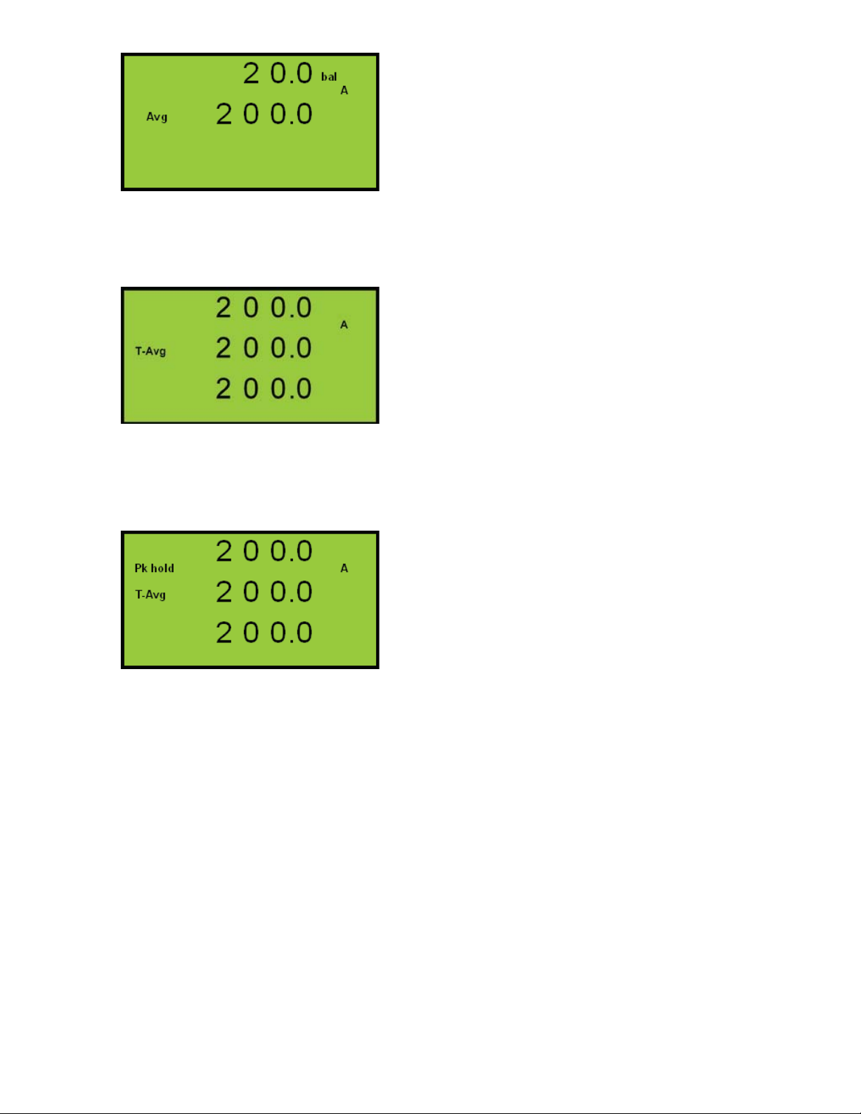
2.1.1 Balance Current Measurements........................................... 5
2.1.2 Time Averaged Amps/Volts (T-Avg) ..................................... 6
2.1.3 Maximum Demand Power (MD)............................................ 6
2.2 POWER UP........................................................................................ 7
2.3 DISPLAY PAGES ................................................................................... 7
3. DISPLAY PAGES............................................................................ 8
3.1 POWER UP........................................................................................ 8
3.2 CURRENT MENU ...............................................................................8-9
3.3 VOLTAGE MENU .............................................................................10-11
3.4 POWER MENU (METER TYPES 1-4) ..................................................11-14
3.5 RESET OF ENERGY REGISTERS ............................................................ 16
3.6 SCROLLING MENU (METER TYPES 1-4)................................................. 16
3.7 METER TYPE DISPLAY MENUS .........................................................17-18
3.8 DISPLAY SCALING .............................................................................. 19
3.8.1 Voltage Scaling................................................................... 19
3.8.2 Current Scaling ................................................................... 19
3.8.3 Power Scaling (W, VA, var)................................................. 19
3.8.4 Energy Registers (Wh, VAh, varh)...................................... 19
3.8.5 Miscellaneous ..................................................................... 19
3.9 ISOLATED PULSE OUTPUTS .................................................................. 20
4. INSTALLATION ............................................................................ 21
4.1 PANEL MOUNTING .............................................................................. 21
4.2 CT CONNECTIONS ............................................................................. 22
4.3 VOLTAGE CONNECTIONS ...................................................................... 22
4.4 AUXILIARY MAINS SUPPLY (L & N)....................................................... 22
4.5 CONNECTION SCHEMATICS.............................................................. 23-25
5. METER SETUP ........................................................................ 26-28
5.1 PROGRAMMING MENU......................................................................... 28
6. OPTIONS ...................................................................................... 28
6.1 INTERNAL MODBUS COMMUNICATIONS ................................................... 28
7. SPECIFICATION ......................................................................29-30
Artisan Technology Group - Quality Instrumentation ... Guaranteed | (888) 88-SOURCE | www.artisantg.com

4
1. Safety
1.1 Warning Symbols
This manual provides details of safe installation and operation
of the meter. Safety may be impaired if the instructions are not
followed. Labels on individual meters give details of equipment
ratings for safe operation. Take time to examine all labels on the
meter and to read this manual before commencing installation.
CAUTION WARNING
Refer to Operating Manual Danger Risk of Electric Shock
Figure 1-1 Safety Symbols
WARNING
The meter contains no user serviceable parts. Installation and
commissioning should be carried out by qualified personnel
1.2 Maintenance
The equipment should be maintained in good working order.
Damage to the product should be repaired by the manufacturer.
The meter may be cleaned by wiping lightly with a soft cloth. No
solvents or cleaning agents should be used. All inputs and supplies
must be isolated before cleaning any part of the equipment.
Artisan Technology Group - Quality Instrumentation ... Guaranteed | (888) 88-SOURCE | www.artisantg.com

5
2. Meter Operation
2.1 Measurements
The GIMA makes use of a high speed micro-processor and an
Analogue to Digital converter to monitor input signals from three
independent phases. Each phase voltage, current and power (kW)
are measured directly and a number of other parameters derived
from these in software. The measurement process is continuous
with all six signals scanned simultaneously at high speed. Unlike
many other sampling systems, which sample one phase after
another, this ensures that all input cycles are detected. Distorted
input waveforms, with harmonics to the 30th are therefore detected
accurately.
Derived parameters are calculated and displayed once a second,
scaled by user programmed constants for current and voltage
transformers.
Instantaneous power parameters are integrated over long time
periods providing a number of energy registers. System frequency
is detected by digital processing of the phase 1 voltage signal.
2.1.1 Balance Current Measurements
The rms. value of the instantaneous sum of the three phase
currents is available on some GIMA meter types. The total current
in a three phase system may be represented as :
Ibal = I1+ I2+ I3= ILEAK + In
ILEAK represents any current leaving the system (e.g. Leakage to earth)
Inrepresents current in the neutral (4 wire systems only)
Note: In 3 phase 3 wire systems the GIMA must be wired using
3 current transformers as shown in fig. 4-3 for balance current
measurement to be made.
Artisan Technology Group - Quality Instrumentation ... Guaranteed | (888) 88-SOURCE | www.artisantg.com

6
2.1.2 Time Averaged Amps/Volts (T-Avg)
Average values of volts and Amps are calculated over a user
programmable time period (10 - 2500 seconds). The displays show
the averages for the most recent time period ending at the time
the display was last updated. The average period is continuously
updated as time progresses.
The largest value of each T-Avg parameter is recorded, saved to
non-volatile memory and displayed as Pk hold T-Avg. These peak
values may be reset by the user.
Each Average-Period is split into 10 sub-periods. The average
values of volts and amps are measured during each sub-period and
stored in an array. The latest sub-period values replace the oldest
in the array as time progresses. The T-Avg values are calculated
as the mean of each corresponding array. The display is updated
with the latest T-Avg parameters at the end of each sub-period
(every Average-Period/10 seconds).
2.1.3 Maximum Demand Power (MD)
Average values of kW, kVA and kvar (if fitted) are calculated over
a user programmable time period (1 - 60 minutes). The displays
show the averages for the most recent time period ending at
the time the display was last updated. The demand period is
continuously updated as time progresses. These parameters are
referred to as Maximum Demand Powers.
The largest value of each MD parameter is recorded, saved to non-
volatile memory and displayed as Pk hold MD. These peak values
may be reset by the user.
Each MD-Period is split into 30 sub-periods. The average power
values are measured during each sub-period and stored in an
array. The latest sub-period values replace the oldest in the array
as time progresses. The MD powers are calculated as the mean
of each corresponding array. The display is updated with the latest
MD values at the end of each sub-period (every MD-Period/30
seconds).
Artisan Technology Group - Quality Instrumentation ... Guaranteed | (888) 88-SOURCE | www.artisantg.com

7
2.2 Power Up
On power up the GIMA shows the meter type and software issue. The
example below shows a GIMA 300 with software issue 1.10.
CUBE
T - 4
SOFT 1.10
2.3 Display Pages
To select current measurements press the AMP key repeatedly
until the desired page is displayed. The number of pages available
is dependant on meter type.
To select voltage measurements press the VOLT key repeatedly
until the desired page is displayed. The number of pages available
is dependant on meter type.
To select power/energy measurements press the POWER key
repeatedly until the desired page is displayed. The number of
pages available is dependant on meter type.
Automatically scrolling pages showing PF, Volts & Amps on each
phase are obtained by pressing SCROLL
Display pages available on the full range of GIMA meters are
shown below followed by tables showing those available on each
standard meter type.
Artisan Technology Group - Quality Instrumentation ... Guaranteed | (888) 88-SOURCE | www.artisantg.com

8
3. Display Pages
Measured data is displayed on the LCD updated every second
unless otherwise stated. Display Pages are organized in four
Standard Menus as follows:
3.1 Power Up
The following screen is shown when auxiliary power is first
supplied.
3.2 Current Menu
Press the AMP key to select from the available Current Menu
pages.
Phase Amps
All Meter Types
Phase 1 true rms amps
Phase 2 true rms amps.
Phase 3 true rms amps.
This display is updated every second.
Peak Hold Phase Amps
G300 & G400 Only
The maximum value of displayed phase
amps. These are stored in non-volatile
memory when the meter loses auxiliary
power
Press AMPS and VOLTS to reset all
three peaks to zero.
Artisan Technology Group - Quality Instrumentation ... Guaranteed | (888) 88-SOURCE | www.artisantg.com

9
System and Balance Amps
G300 & G400 Only
Balance Amps - Instantaneous sum of
the phase current waveforms. This is a
measure of the neutral current + earth
leakage.
System Average Amps =
(Irms1 + Irms2 + Irms3)/3.
Time-Averaged Amps
G100 through G400
The calculated average of phase amps
taken over a user definable time period
TVI (10s to 2500s).
A rolling time window is used and the
display updated every TVI/10 with the
average of the most recent period
displayed.
Peak Time-Averaged Amps
G100 through G400
The maximum value of Time- Averaged
amps. These are stored in non-volatile
memory when the meter loses auxiliary
power
Press AMP and VOLTS to reset all
three peaks to zero.
Artisan Technology Group - Quality Instrumentation ... Guaranteed | (888) 88-SOURCE | www.artisantg.com

10
3.3 Voltage Menu
Press the VOLTS key to select from the available Voltage Menu
pages.
Phase Volts
All Meter Types
Phase 1 True rms volts
Phase 2 True rms volts.
Phase 3 True rms volts.
This display is updated every second.
Line Volts
All Meter Types
Line 1 Volts (Phases 1-2)
Line 2 Volts (Phases 2-3)
Line 3 Volts (Phases 3-1)
This display is updated every second.
Peak Hold Phase Volts
Meter Type G300 & G400
The maximum value of displayed phase
volts. These are stored in non-volatile
memory when the meter loses auxiliary
power
Press AMP and VOLTS to reset all
three maximums to zero.
Time-Averaged Volts
All Meter Types
The calculated average of phase volts
taken over a user definable time period
TVI (10s to 2500s).
A rolling time window is used and the
display updated every TVI/10 with the
average of the most recent period
displayed.
Artisan Technology Group - Quality Instrumentation ... Guaranteed | (888) 88-SOURCE | www.artisantg.com

11
Peak Time-Averaged Volts
All Meter Types
The maximum value of Time- Averaged
volts. These are stored in non-volatile
memory when the meter loses auxiliary
power
Press AMP and VOLTS to reset all
three maximums to zero.
3.4 Power Menu (Meter Types G100-G400)
Press the POWER key to select from the available Power Menu
pages.
System Power (kW)
Meter Types G100 through G400
System Real Power (Watts)
Frequency (Measured on V1)
System, PF
A symbol after the PF value
indicates a capacitive load.
System Power (kVA)
Meter Type G400 Only
System Apparent Power (VA)
Frequency (Measured on V1)
System, PF
A symbol after the PF value
indicates a capacitive load.
System Power (kvar)
Meter Types G300 & G400 Only
System Reactive Power (VAr)
Frequency (Measured on V1)
System, PF
A symbol after the PF and kvar
values indicate a capacitive load.
Artisan Technology Group - Quality Instrumentation ... Guaranteed | (888) 88-SOURCE | www.artisantg.com

12
Phase Watts
Meter Types G100 through G400
Phase 1 watts
Phase 2 watts.
Phase 3 watts
Phase VA
Meter Type G400 Only
Phase 1 VA
Phase 2 VA.
Phase 3 VA
Phase var
Meter Types G300 & G400 Only
Phase 1 var
Phase 2 var.
Phase 3 var
A symbol after a var value
indicates a capacitive load.
A negative sign before a var reading
indicates export reactive power.
Artisan Technology Group - Quality Instrumentation ... Guaranteed | (888) 88-SOURCE | www.artisantg.com

13
Mean Demand (MD)
Meter Types G300 & G400 Only
The calculated average of the system
power values taken over a user
definable time period Tp(1min to 60min).
A rolling time window is used and the
display updated every Tp/30 with the
averages of the most recent period
displayed.
Peak Hold MD
Meter Types G300 & G400 Only
The maximum value of each power MD
value. These are stored in non-volatile
memory.
Press AMP and VOLTS to reset all
three maximums to zero. See attached
link option on page.
Real Energy (Wh)
Meter Types G200 through G400 Only
This register accumulates when kW is
positive (import).
This value returns to 0 when the value
exceeds 99999999.
This register is stored in non-volatile
memory when auxiliary power is not
supplied to the meter.
*Press AMP & VOLTS and hold for 5
seconds to reset Kwh to zero if this
option is installed.
Artisan Technology Group - Quality Instrumentation ... Guaranteed | (888) 88-SOURCE | www.artisantg.com

14
Apparent Energy (VAh)
Meter Type G400 Only
VAh Accumulating register.
This value returns to 0 when the value
exceeds 99999999.
This register is stored in non-volatile
memory when auxiliary power is not
supplied to the meter.
Reactive Energy (varh)
Meter Type G300 & G400 Only
Import varh Accumulating register.
This value returns to 0 when the value
exceeds 99999999.
This register is stored in non-volatile
memory when auxiliary power is not
supplied to the meter.
Reactive Energy Inductive
Meter Types G300 & G400 Only
This register is separate from the main
import varh register and accumulates
only when the measured load is
inductive.
This register resets at 99999999 and is
saved in non volatile memory.
Reactive Energy Capacitive
Meter Types G300 & G400 Only
This register is separate from the main
import varh register and accumulates
only when the load is capacitive.
This register resets at 99999999 and is
saved in non volatile memory.
NOTE 1: Meters may be supplied with all Peak Reset keypad
functions disabled.
NOTE 2: Meters may be supplied with an Energy Reset Option
(ref section 5)
Artisan Technology Group - Quality Instrumentation ... Guaranteed | (888) 88-SOURCE | www.artisantg.com

15
GIMA Option Links
1. Option Links
WARNING
Risk of Electric Shock!
Isolate the instrument supply and all inputs before accessing the option links
Four option links may be accessed on the rear of the GIMA display
PCB. Meters are normally shipped with all these links fitted.
*Not customer programmable. Contact Simpson before changing.*
1.1 Option Link Detection
For safe operation the instrument supply and all inputs must be isolated before
accessing option links. The link settings are only detected during power-up of the
auxiliary supply to the meter
2. Enable Programming Menu (Link1)
If this link is removed the user may not gain access to the programming menu
using the front panel keys. For further details of programming the GIMA refer to the
meter operating instructions.
3. Disable Reset Energy (LINK2)
If this link if fitted the Energy Registers may be reset by:
Press Pto display any energy register
Press AMP and VOLTS together and hold until energy resister resets to zero
(approx 5S).
If this link is removed the Energy Registers may not be reset
NOTE: Once reset to zero the accumulated energy readings may not be recovered.
4. Disable Reset Peaks (LINK3)
If this link is removed the peak hold and peak demand values may be reset by:
Select any display page showing a Peak Hold or Peak Demand value.
Press AMP or VOLTS together and hold until the peak value resets to zero (approx
2S).
If this link is fitted the peak and peak demand values may not be reset
NOTE: Once reset the zero and peak and peak demand values will be replaced by
values measured in the following second.
5. Pulse Output #2 (LINK4)
If this link is fitted the second pulse output will be triggered by changes in the
import kvarh register.
If this link is omitted the second pulse output will be triggered by changes in the
kVah register.
Artisan Technology Group - Quality Instrumentation ... Guaranteed | (888) 88-SOURCE | www.artisantg.com

16
3.5 Reset of Energy Registers
Meters may be supplied with an option to reset energy registers
to zero using the front keys. If the option is fitted, press AMP and
VOLTS together while displaying any energy register and hold for
approximately 3 seconds. All energy registers are simultaneously
reset to zero. Once reset the registers may not be recovered.
3.6 Scrolling Menu (Meter Types G100 through G400)
Press the SCROLL key to select the Auto Scrolling Per-Phase
Menu.
Per-Phase Display Pages
Meter Types G100 through G400
Three pages show the Amps Volts
and Power Factor of phases 1-3
consecutively.
The Phase automatically advances after
approximately 5 seconds.
A symbol indicates a capacitive
load.
Press the SCROLL key to advance the scrolling pages more
quickly.
Artisan Technology Group - Quality Instrumentation ... Guaranteed | (888) 88-SOURCE | www.artisantg.com

17
3.7 Meter Type Display Menus
G100 Menus
AMPS VOLTS POWER SCROLL
Phase Amps Phase Volts System Power (kw),Hz,PF Phase 1 PF, V, I
Time Averaged Amps Line Volts Phase Watts Phase 2 PF, V, I
Peak Time Averaged
Amps
Time Averaged Volts Phase 3 PF, V, I
Peak Time Averaged
Volts
G200 Menus
AMPS VOLTS POWER SCROLL
Phase Amps Phase Volts System Power (kw),Hz,PF Phase 1 PF, V, I
Time Averaged Amps Line Volts Phase Watts Phase 2 PF, V, I
Peak Time Averaged
Amps
Time Averaged Volts Import Real Energy (Wh) Phase 3 PF, V, I
Peak Time Averaged
Volts
G300 Menus
AMPS VOLTS POWER SCROLL
Phase Amps Phase Volts System Power (kw),Hz,PF Phase 1 PF, V, I
Time Averaged Amps Line Volts System Power
(kvar),Hz,PF
Phase 2 PF, V, I
Peak Time Averaged
Amps
Time Averaged Volts Phase Watts Phase 3 PF, V, I
Peak Time Averaged
Volts
Phase var
Maximum Demands (MD)
Peak Hold MDs
Import Real Energy (Wh)
Import Reactive Energy
(varh)
Reactive Energy Inductive
Reactive Energy
Capacitive
Artisan Technology Group - Quality Instrumentation ... Guaranteed | (888) 88-SOURCE | www.artisantg.com

18
G400 Menus
AMPS VOLTS POWER SCROLL
Phase Amps Phase Volts System Power (kw),Hz,PF Phase 1 PF, V, I
Peak Hold Phase
Amps
Line Volts System Power
(kVA),Hz,PF
Phase 2 PF, V, I
System and Balance
Amps
Peak Hold Phase
Volts
System Power
(kvar),Hz,PF
Phase 3 PF, V, I
Time Averaged Amps Time Averaged Volts Phase Watts
Peak Time Averaged
Amps
Peak Time Averaged
Volts
Phase VA
Phase var
Maximum Demands (MD)
Peak Hold MDs
Import Real Energy (Wh)
Apparent Energy (VAh)
Import Reactive Energy
(varh)
Reactive Energy Inductive
Reactive Energy
Capacitive
Artisan Technology Group - Quality Instrumentation ... Guaranteed | (888) 88-SOURCE | www.artisantg.com

19
3.8 Display Scaling
Measured values displayed on the LCD are scaled by the user
settings of CT and/or PT primaries to provide optimum resolution.
3.8.1 Voltage Scaling
PT Setting Resolution
10VL-L - 80VL-L 0.01 V
81VL-L - 800V 0.1 V
801VL-L – 8,000VL-L 1 V
8,001VL-L - 80,000VL-L 0.01 kV
>80,000VL-L 0.1kV
3.8.2 Current Scaling
CT Setting Resolution
5A - 8A 0.001 A
9A - 80A 0.01 A
81A - 800A 0.1 A
801A – 8,000A 1 A
>8,000A 0.01 kA
3.8.3 Power Scaling (W, VA, var)
PT Setting x CT Setting Phase Parameters System Parameters
100VA - 1,400VA 0.1 W 0.001 kW
1,401VA - 14,000VA 0.001 kW 0.01 kW
14,001VA - 140,000VA 0.01 kW 0.1 kW
140,001VA - 1,400,000VA 0.1 kW 1 kW
1,400,001VA - 14,000,000VA 1 kW 0.01 MW
14,000,001VA - 140,000,000VA 0.01 MW 0.1 MW
140,000,001VA – 1,000,000,000VA 0.1 MW 1 MW
3.8.4 Energy Registers (Wh, VAh, varh)
PT Setting x CT Setting Resolution
100VA - 1,400VA .001 kWh
1,401VA - 14,000VA 0.01 kWh
14,001VA - 140,000VA 0.1 kWh
140,001VA - 1,400,000VA 1 kWh
1,400,001VA - 14,000,000VA 0.01 MWh
14,000,001VA - 140,000,000VA 0.1 MWh
140,000,001VA – 1,000,000,000VA 1 MWh
3.8.5 Miscellaneous
All Settings Resolution
System and Phase PF 0.001
THD 0.1%
Harmonics 0.1%
Frequency 0.1 hz
Artisan Technology Group - Quality Instrumentation ... Guaranteed | (888) 88-SOURCE | www.artisantg.com
Other manuals for Simpson 400
1
Table of contents
Other Gima Measuring Instrument manuals